Brunsviga G n° 13944
Well, this must probably be among my most sensational finds so far. A couple, about my age, and located in the north of France, was clearing out grandfather's attic after he passed away, and put a few things onto a well-known French auction site.
The photo appeared to show a Brunsviga Modell H, which is very similar to the Modell J, but with an extra counter register at the top. That is very exciting, because only 140 were ever built! However, the picture was a little odd, because there appeared to be shown an extra wingnut at the left end of the carriage, and if you looked at the picture really thoroughly, there appeared to be an extra comma bar at the bottom of the carriage too.
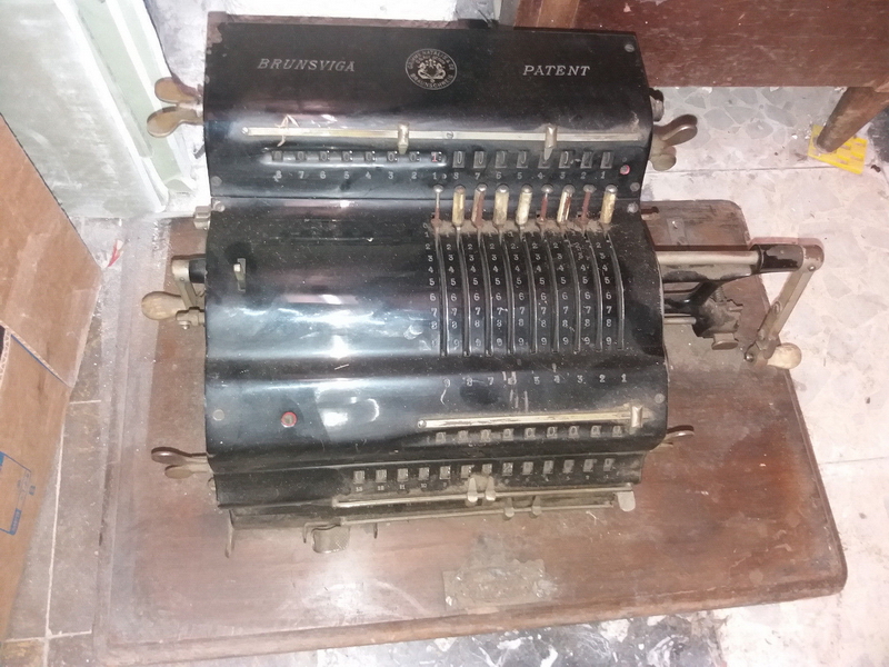
When I arrived to pick it up, it became clear that it was in fact a Brunsviga G
Estimates of the Brunsviga serial numbers put it at the end of 1908, but the Neumann plate on the base of the machine lists the telephone number "CENTRAL 90-01".
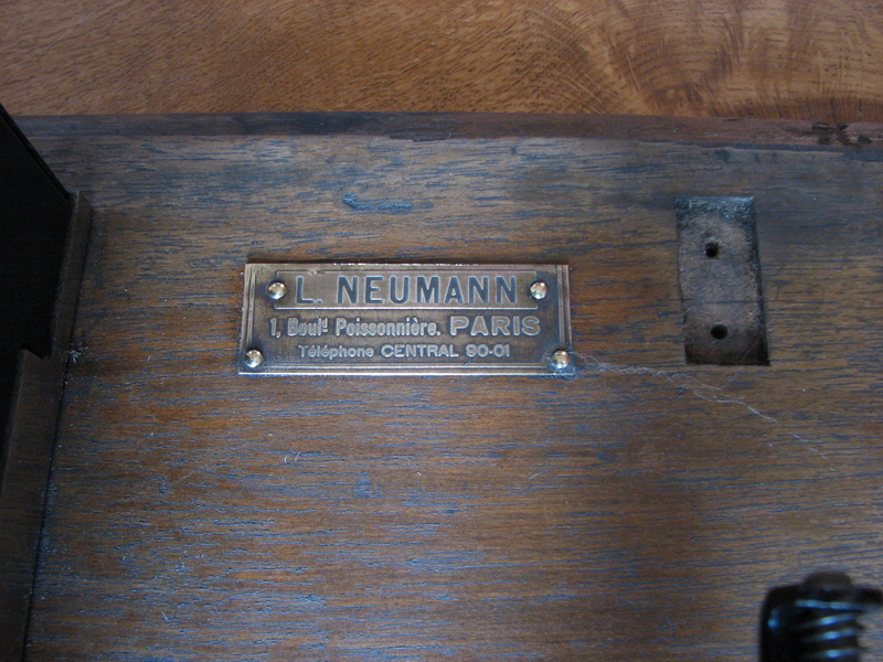
The Paris telephone centrals only switched to this numbering in October 1912, so either the machine stood around for a few years and was only sold later, or the plate was changed when it came in for maintenance to reflect current contact details.
The grandfather who owned the machine was a cobbler, and probably not interested in doing his bookkeeping with such a massive and expensive machine (not considering that he probably wasn't even born yet in 1908)... the grandchildren thought that he would have gotten it in payment for shoes or shoe repairs, possibly during the second world war, or even later. It may have been in need of repairs by then, too. In any case, after being used very intensively for a long time (there is a lot of wear), it spent a few quiet decades sitting broken in the attic without being touched, before being dug out, sold to me, and now restored.
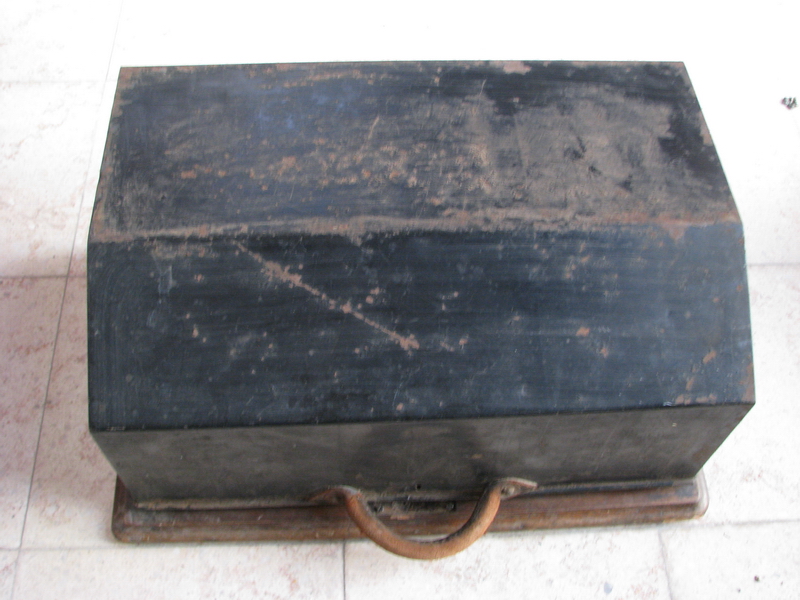
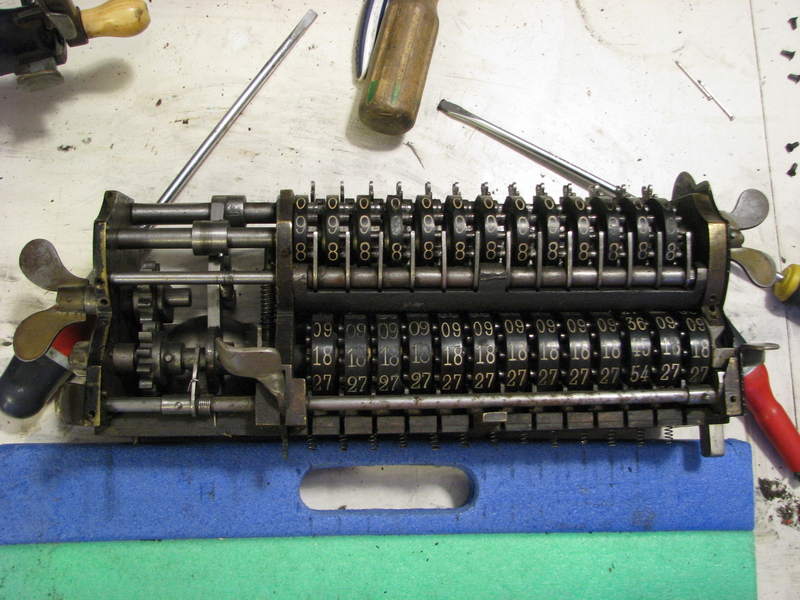
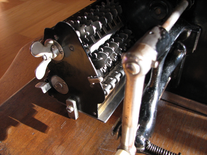
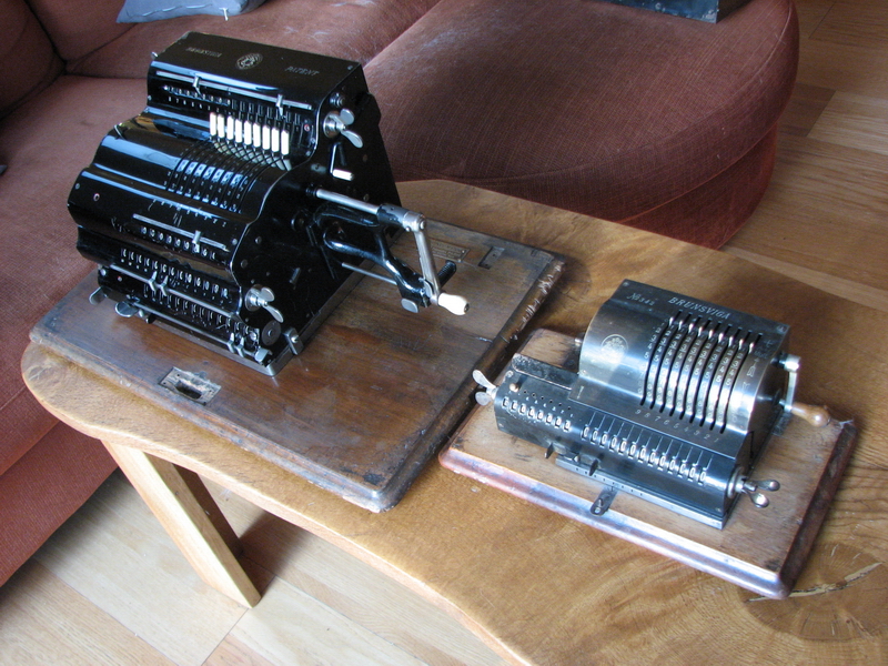
Now, first some pictures of the machine as it arrived.
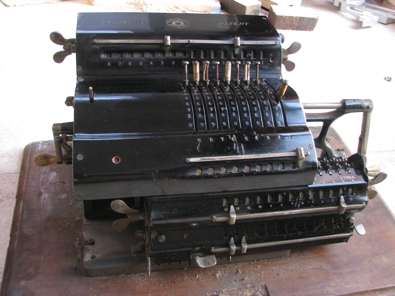
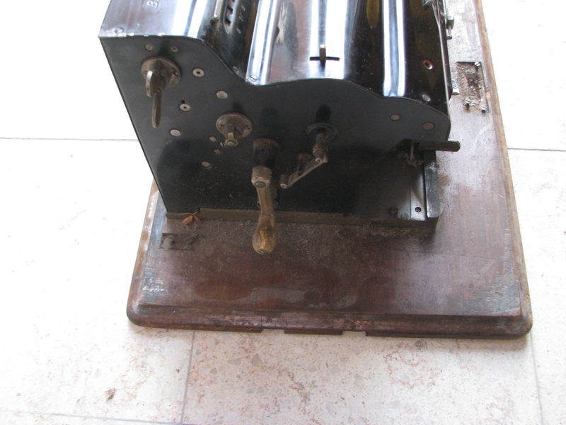
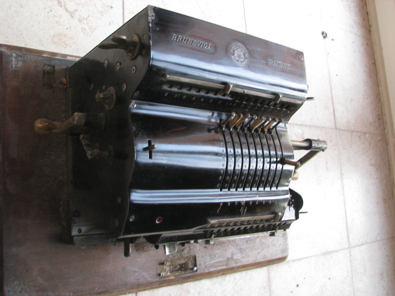
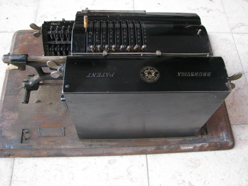
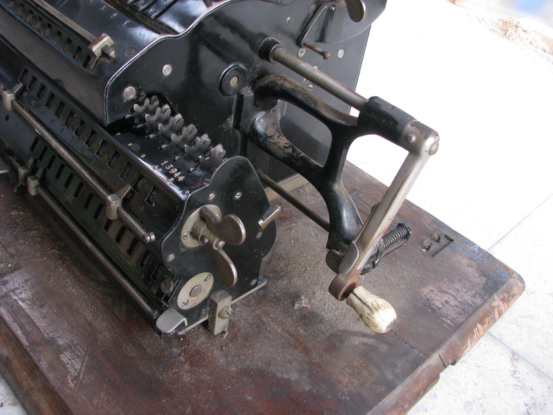
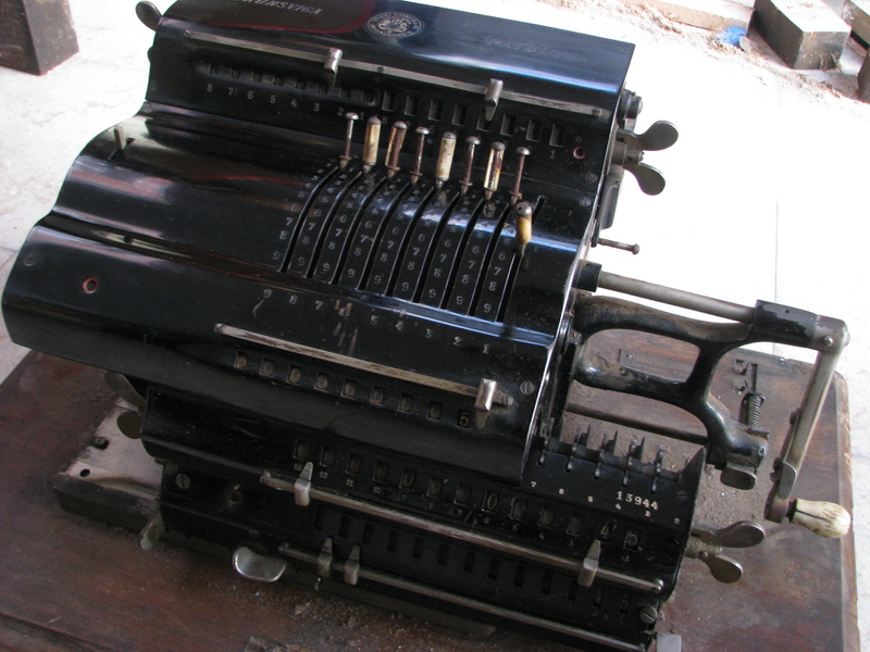
The most striking thing about the appearance of the machine was that all the ivory handles had apparently collected moisture and rusted the metal that lay underneath. Because rusting iron swells, all of them, except the handle on the left for the clearing of the input, had cracked, and this undamaged handle was firmly stuck on the crank. Other than that, the machine was in surprisingly good condition with little rust, it was just very dirty. The carriage wouldn't move - on inspection, the reason for this was a locking block to prevent damage in transport - smart! The bottom result register had three numeral wheels replaced with home-made ones earlier in the life of the machine.

One numeral wheel, however, wouldn't rotate past 3, and also wouldn't clear. The rotation issue was caused by a broken gear tooth on this numeral wheel, and the clearing issue by a broken tooth on the clearing axle. Two teeth on the clearing axle, including the broken one, had previously been replaced. This confirms, together with the worn nickel coating on all the wingnuts, and substantial abuse of the fine-toothed gear in the rotation direction safety, that the machine had had a long and active career.
The necessary repairs then had to be effected. The metal caps for the setting levers were taken off by gripping them firmly with a large pair of rusty vise-grips and twisting until... (oh, the horror ...). No, obviously that was a (bad) joke. Please refrain from using vise-grips, unless the part you are using them on was destined to be scrapped anyway. The caps for the setting levers have two holes for a pin wrench. It works well to grind the beaks of a pair of needle-nose pliers until they fit, with the added advantage that the width of the pins will then be adjustable "on the fly".

After the caps were off, the worst of the rust was cleaned up, and the two remaining ivory handles soaked with WD40 in order to get them free. A pin wrench is also needed to twist the end caps of the cranks off. The main crank handle had been abused with pliers before (apparently the rust issue had been around even when someone last took an interest in the machine...) - it is important to cushion the grip of pliers with a piece of rubber sheet or thick cardboard or paper to prevent damage to the part from the serrations of the pliers when trying to (carefully) break it loose - that worked without issue, helped by the lengthwise crack that ran all over the length of the grip on the main crank - but even the uncracked input zeroing handle gave up its death grip without much of a fight. They were cleaned up, the rust filed out of the inside with a needle file, and the main crank handle spent the night in a vise, being glued back together with wood glue. The other handle, from the input clearing lever, got the same treatment, but it was neither damaged nor cracked, so it was just cleaned up, as was the rust on the handles themselves.
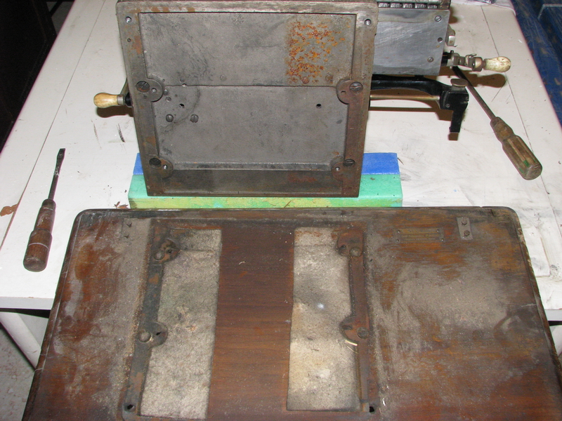
Then I brushed down the machine to get the worst of the dirt and dust off, and took off all the covers. I undid the connection from the revolution counters to the carriage from the back of the machine, and slid out the carriage to the right. I brushed and wiped the dust and dirt out of the inside and wiped whatever steel or brass parts I could reach, as well as the base plate of the machine. Once this was done, all the oiling points were oiled, a blocked tens carry wheel in the revolution counter gently levered back in place, and then all the brightwork on the main body of the machine was polished up. The carriage remained "dans son jus" for the time being...
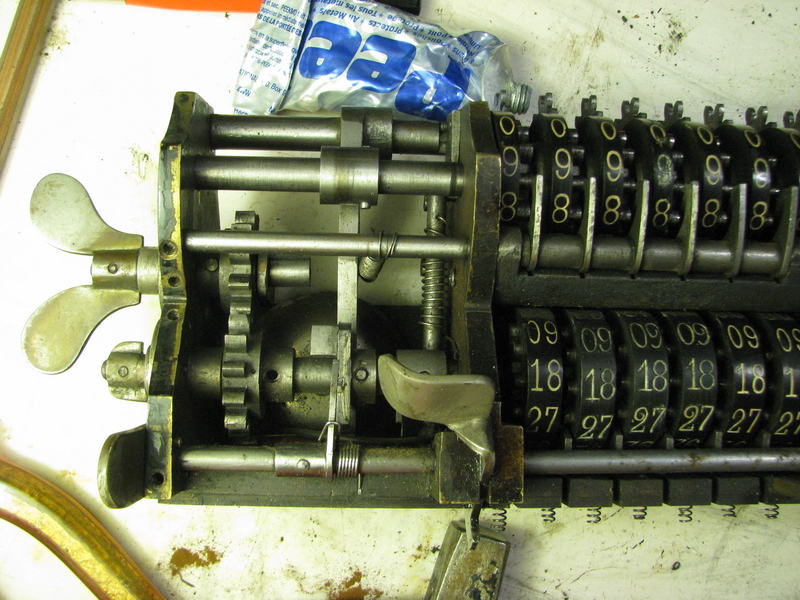
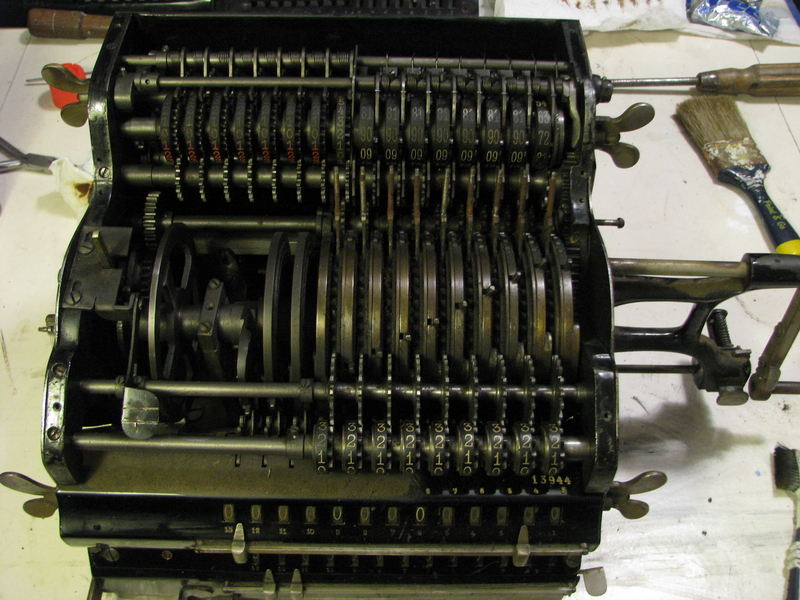
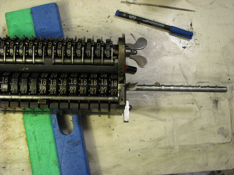
It had become clear by now that the carriage would have to be disassembled to make repairs to the numeral wheel and the clearing axle. The clearing axle for the bottom register is operated by a gear from the wingnut at the left of the carriage. This gear is pinned to the axle with a tapered pin (already removed in the bottom picture). Then, in the middle, there is the safety that prevents clearing when the pinwheel cylinder is not in its rest position, together with the safety that prevents clearing when the carriage is not in its rightmost position, and the "unlock" feature that allows the complements lever ("N" in the drawing above) to spring back - again pinned. Finally, behind the carriage release button ("T"), there is the reset lever for the complements shroud, pushing it back to the "normal" position on clearing. So those are three pins that have to be driven out - we'll get back to that. Then the spring loaded snap lock at the left was unscrewed, and an attempt was made to remove the clearing axle to the left of the carriage. No such luck - no channel is provided in the middle carriage support for the clearing teeth. This means the axle has to come out to the right instead, and the snap lock at the left end, which is pinned in place too, also needs to come off. I have a set of pin punches that offer good service, but below 2mm I find it becomes rather iffy not to bend the punch when giving it a decisive tap with a light hammer (and finding those narrow punches is a problem too, probably for this reason ...). The three pins inside the carriage came out without much of a fight with the 2mm punch, but the one holding the snap lock was narrower, and that complicates matters somewhat. What I ended up doing was grinding a flat end on 1.5mm steel nail, hold that in a pair of needle-nose pliers against the end of the pin, and hit the end of it. It's too short to bend, and so far it has worked for me every time - as long as you make sure you hit the narrow end of the tapered pin! This procedure nevertheless caused me a lot of stress for a different reason, because while faffing about with the pin, suddenly a part fell out of the carriage that had clearly broken off something, and I was unable to find where. And after much initial consternation, I still haven't. I am now assuming that it must have been something that did not belong to the machine in the first place, but was accidentally dropped into the carriage somewhere during its 110 year life, because after duly checking everything, I honestly have no clue where it could possibly have come from!

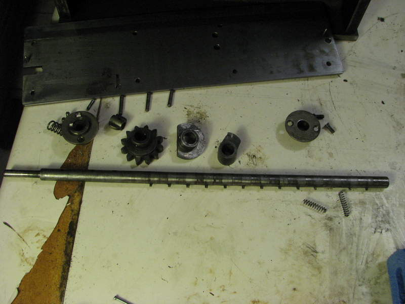
With the clearing axle out, the broken wheel in position 3 could be accessed, and the damage to the axle assessed. I decided to file a new tooth that would fit the numeral wheel, and glue it in place, not completely trusting the ability of the black rubber of the numeral wheels to withstand the heat of soldering. In addition, I decided to move the affected wheel to position 12 in the carriage (the last numeral wheel in position 13 is different, because it has to operate the bell), to limit the stress from operation. That turned out not to be such a good idea - see below.
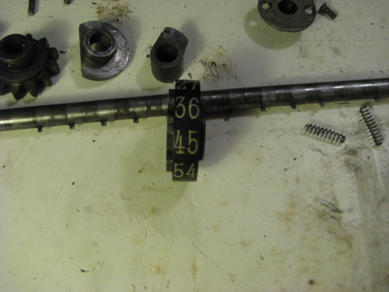
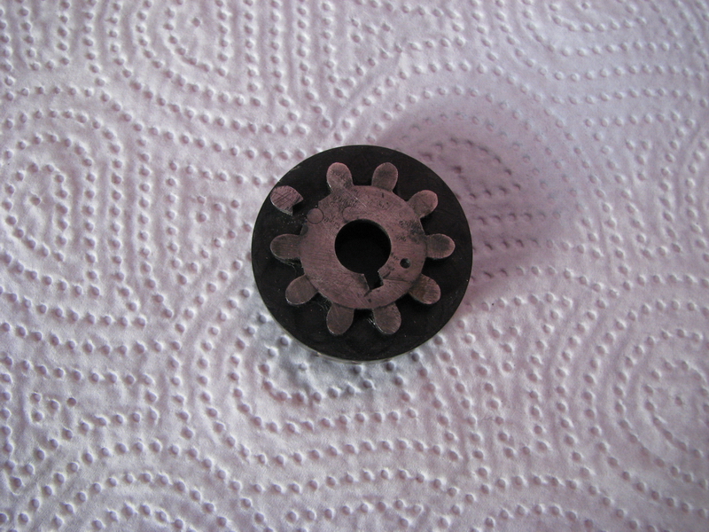
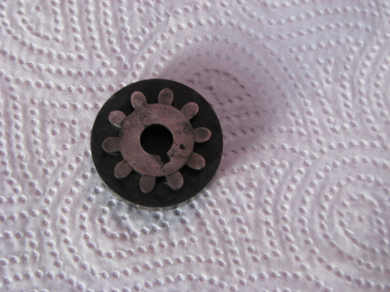
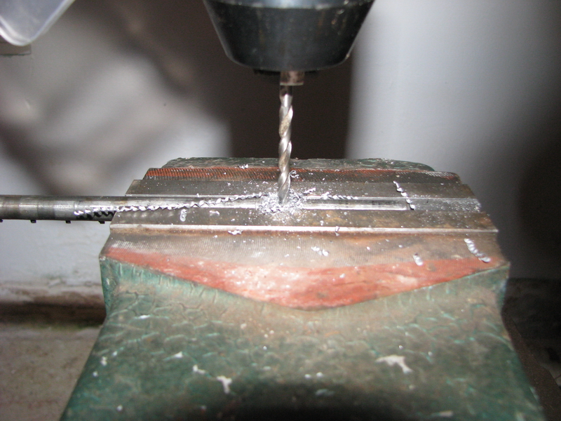
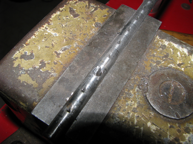
The axle itself needed clearing tooth nr. 3 replaced. A simple question of drilling it out, pressing in a new piece of steel, measuring carefully, and grinding and filing the new tooth to shape. Well, as usual, we all know it wouldn't be so easy, would it ?
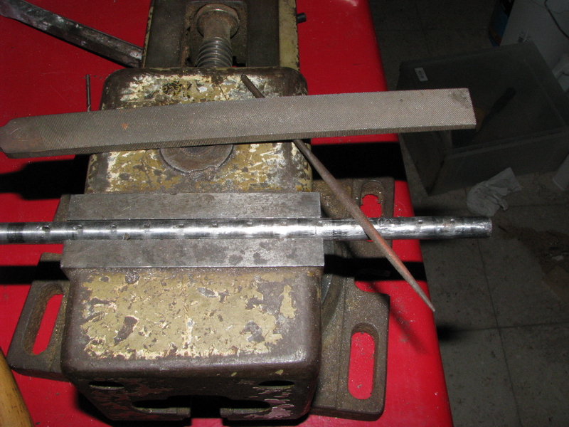
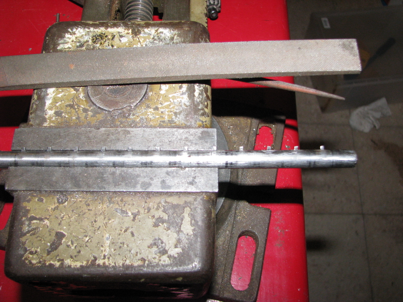
So, on reassembling the carriage, it turned out that, with the wheels switched, the alignment was off. These machines are hand-fitted together, and everything really needs to go back into its proper place in order to work as intended ... because of this, and because the clearing tooth I filed was a bit marginal in size, the adjustments that I made to the order of the numeral wheels caused too much binding, and eventually I ended up breaking off a second clearing tooth during testing, while trying to clear all the numeral wheels in the carriage at the same time. So everything had to come apart again while this was duly repaired, and the new clearing tooth nr. 3 was replaced with a better fitting example at the same time. I also decided to switch the numeral wheels back to their original positions. Then, I disassembled the entire bottom register to clean and oil everything, and this finally fixed the issues with binding. However, there was something else that I didn't quite think of. The bottom register is much further away from the pinwheel cylinder, because it has to be visible to the user, and thus, it has to be turned via intermediate gears. The tens' carry for this register though, still needs to be positioned next to the pinwheel cylinder for it to be able to operate. Conclusion: the tens' carry tooth, which is normally situated on the numeral wheel, sits on the intermediate gear instead in the bottom register of this machine. If you take the numeral wheel out, this gear is free to rotate (and it will, while disengaging the numeral wheel). When everything was reassembled and the carriage cleared properly, it turned out that the bottom register now mainly had fives', sixes' and eights' carries instead of tens' carry. Insert suitable expletive here, and have a break. So - everything comes apart yet again (and that includes tapping out those four conical pins every time, and lining everything up for getting them back in afterwards).
After some experimentation to find the proper orientation of the gears so that they would line up for tens' carry after the numeral wheel had been popped back in (they also rotate over two positions when putting them back), I then reassembled the carriage for the final time, also putting the covers back on, including the shroud that allows to calculate with complements in the bottom register. Then I left the machine for the night. However, as usual, the venom is in the tail here ...
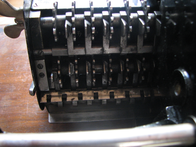
The next evening on which I had time to work on the machine again, I arrived at the workbench finding it to be completely blocked. I could clear all registers, but I could not rotate the main crank in the positive direction at all, and could only make half a turn in the negative sense. Neither could the carriage be moved at all - which is a bit of a problem, as I wanted to take it out to do some more work on it. It took some detective work to figure out what was going on, and it turned out to have to do with this complements feature in the bottom register. If you want to calculate negatively by using complements, you will find that the complement of e.g. 00000 that results from moving the shroud, is, according to the machine, 99999, while it should of course also be 00000. This Brunsviga solves this problem by operating an extra carry lever in the rightmost position, when the shroud is moved to "negative". In order to prepare the register for negative calculation, one should press the lever for complements, and at that point the special carry lever to the right of position 1 (the one stamped "1", bottom left in the bottom (third) picture below) moves out, into a special slot in wheel 1 of the pinwheel cylinder, which then prevents it from making a positive turn, acting as a safety.
Here it is "in":

Here it is "out"
And here you can see it at the bottom left, stamped with "1":
The next turn of the main crank should now be negative (as you would expect it to be anyway), which will then run the carries all the way through both the bottom register, and change it to 00000 instead of 99999. However, a full series of carries takes rather a lot of force, hence the apparent blocking of the main crank halfway through the negative turn - and I was afraid to damage something. And of course I had forgotten at that point that I had pushed the complements lever the previous evening. Clearing the bottom register will pop the lever "N" back up and move the shroud back to its normal position, but the tens' carry lever still stays out, blocking the machine. On finding this out, poking in with a long thin screwdriver clicked the tens carry lever back into its rest position, and all was well again. The carriage now moved, and in this way allowed me to verify how everything should operate, before gathering the courage to actually try it. And sure enough, with a bit more grunt behind the main crank on turning anticlockwise, everything went exactly as advertised - phew! Trautschold actually describes this behavior in his monograph (see below), but on the other hand stresses every time it is featured in the text that the machine should not be forced to prevent damage to the safety feature - I sense that this would have been a common repair to machines so equipped ...
There is another interesting technical solution involved, that doesn't exactly help with this problem. Tens' carry on a pinwheel machine works by the tens carry levers on the back of the carriage moving out, and a special tens' carry pin on every pinwheel will be guided by these levers into engagement with the associated numeral wheel gear of the next position up, and rotate it by one tooth/number. This must, however, be carefully timed, because every carry needs the time to set the tens' carry lever of the next position up, before the next carry pin on the pinwheel cylinder arrives there. Since the system must work to the front as well as to the back, what you have is a half spiral of carry pins over half the circumference of the pinwheel cylinder for the positive direction, and the same thing for the negative direction. However, now they introduced an extra carry pin which can only work in negative direction, and should operate before all the other carries. There simply isn't space on the cylinder to accommodate this extra pin, so the Brunsviga engineers developed a tailor-made solution - the "extra" carry pin at the far right of the pinwheel cylinder is more or less at the same position around the circumference of the cylinder as, and physically connected to, the next carry pin on the pinwheel cylinder - so they move simultaneously. That means that the rightmost wheel will be carried one position up, and at the same time it does that, and while pushing the carry lever of numeral wheel 2 into its operating position, already tens' carry pin 2 is passing there, moved out to gear n° 2, not because of its tens' carry lever, but because it is physically connected to the first carry pin, that is operated by the "special" carry lever at the far right. But that makes the first carry just that little bit heavier, because you're trying to move two numeral wheels and two carry levers almost simultaneously, to be able to respect the timing of the rest of the carries. And it makes it slightly more prone to blocking! The problem is less of a problem if you actually have a number set in the setting register on this first negative turn that you ahve to make, as you would in normal operation. But demonstrating this feature with an empty setting register is setting up a perfect storm for turning the machine into a doorstop. It can be fixed without any disassembly by unlocking the rotation lock, turning the handle back to the rest position, setting "1" in the setting register, and then trying to make a negative turn again - the tens will carry, and all will be well.
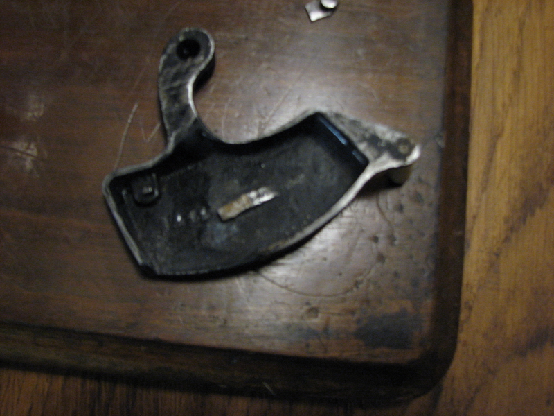
A similar operating tactic is necessary when switching the right counter register to complements, both in the Brunsviga G and H - this also blocks the main crank from turning in the positive sense, by an interlock in the gear train from the main crank - the first turn of the crank should be in negative sense, which then operates the carries, and in addition it should add another 1 in the rightmost position, so that the result shown is correct (after all, you're also just making a turn of the crank, so the counter register should count up or down anyway - in the result register, this doesn't matter, because you can also calculate with 0 in the setting register). This "extra" count didn't work correctly. If the "M" lever was pulled with the register on 0, it would duly switch the blind and show all 9's, but on making the required negative turn, it would switch to all 0's instead of 000001. Obviously, that would not do. The actual mechanism that gives the extra push to the first numeral wheel is invisibly hidden deep inside the machine, but its actuator lives behind the housing of the "M" lever on the right side of the machine. This is that spot with the lever taken off.

...and this is the inside of the lever casting:
The raised ramp in the middle of the lever is supposed to press in the roundish metal part. This in turn does something in the inside of the machine that makes the first counter position operate during the first 10-20° of counterclockwise operation, and then tilts the squarish part with the large screw, so that the locked lever is released and springs backwards. If the counter register was initially at all 9's, then this will also operate the entire train of carries, switching the register to all 0's. Then, around -90° rotation of the main crank, the "normal" counting event occurs. So in total the counter register thus accummulates -2, instead of -1 during a normal backwards rotation.
Due to wear on the ramp in the middle of the cast iron lever, the round button was not depressed enough to make this first additional counting event happen. I filed a suitable piece of 1mm thick steel and stuck it on top of the ramp with superglue (soldering cast iron is a complete nightmare - solder really doesn't like carbon!). Problem solved.
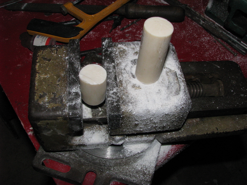
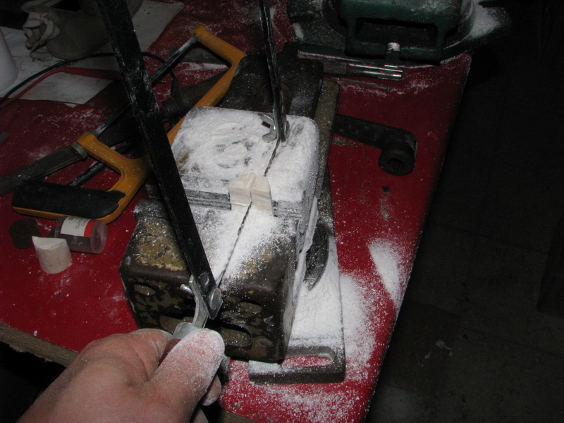
The last hurdles were now to remake the ivory shrouds for the setting levers - a job I have put off for a long time for some of the other Brunsvigas with non-moving setting levers that I have, because not only is it a lot of work, it is also difficult, for the simple reason that the replacement plastic you can buy instead of ivory has some of the same rather disagreeable properties as ivory itself when shaping it - it stinks to high heaven, creates a giant pile of fluffy white dust, and to add insult to injury, it is brittle and has an annoying tendency to snap, just when the part you are making is almost finished.
Pictures of the process - this is a rod of fake ivory, which, when cut off to length, and divided in 4, will just give four 7mm cylinders.
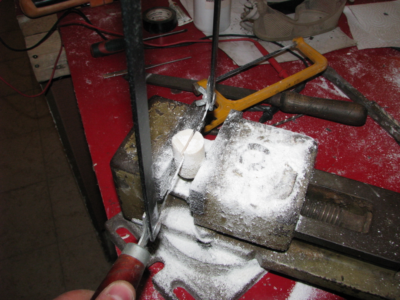
Sawing - yuck!
Halves
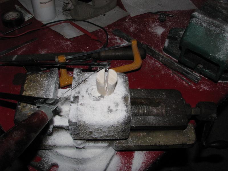
Quartered
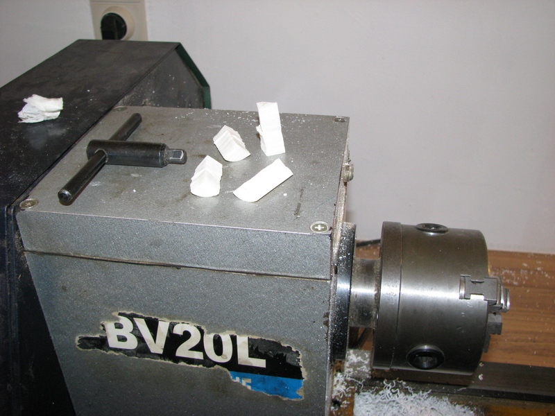
Ready for turning
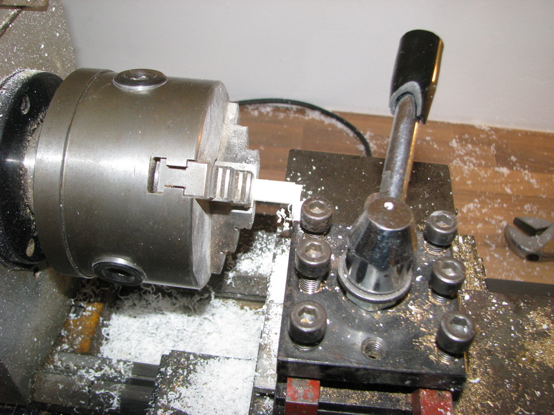
Gripped in the lathe chuck
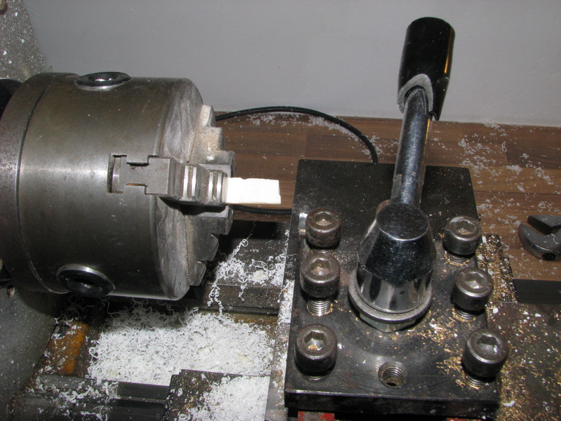
Turning to size ...
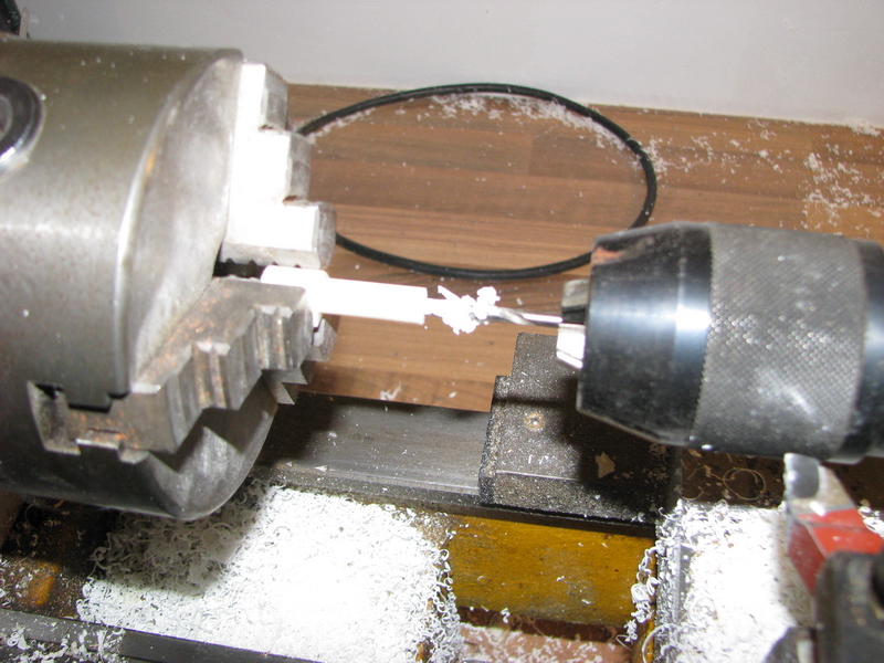
Drilling 3.3mm
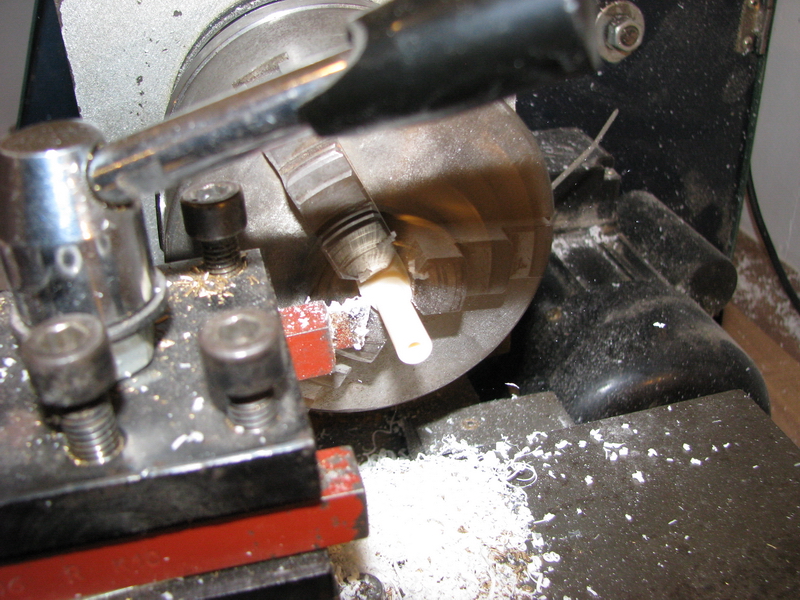
Cutting off - carefully!
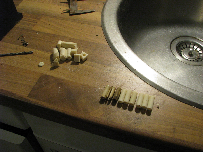
And - finished - plus the three remaining original cylinders, and all the broken bits and pieces that went wrong!
At the beginning of 2018, the machine ended up in the Arithmeum in Bonn, the largest museum and library on the history of calculation, where it will be kept safe in the collection, and hopefully also go on display. I hope to be able to snap a picture of it in its new surroundings sometime soon!