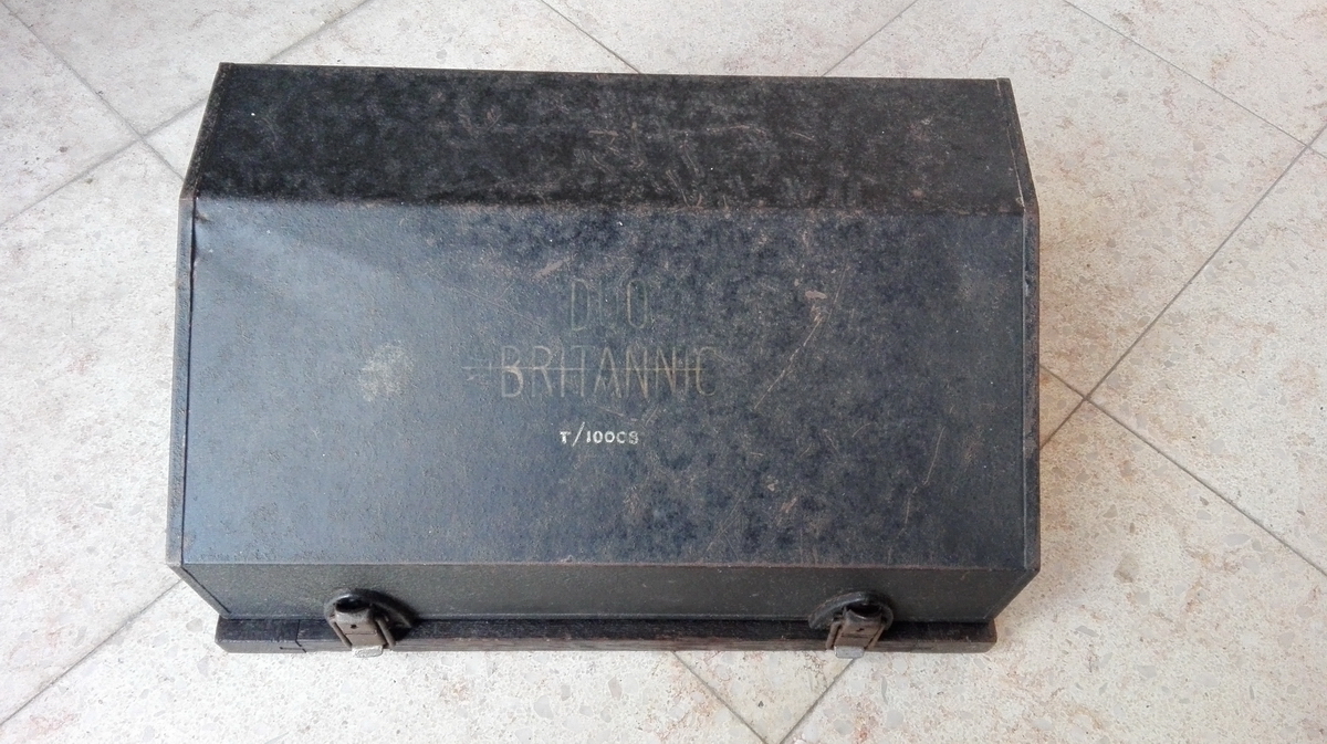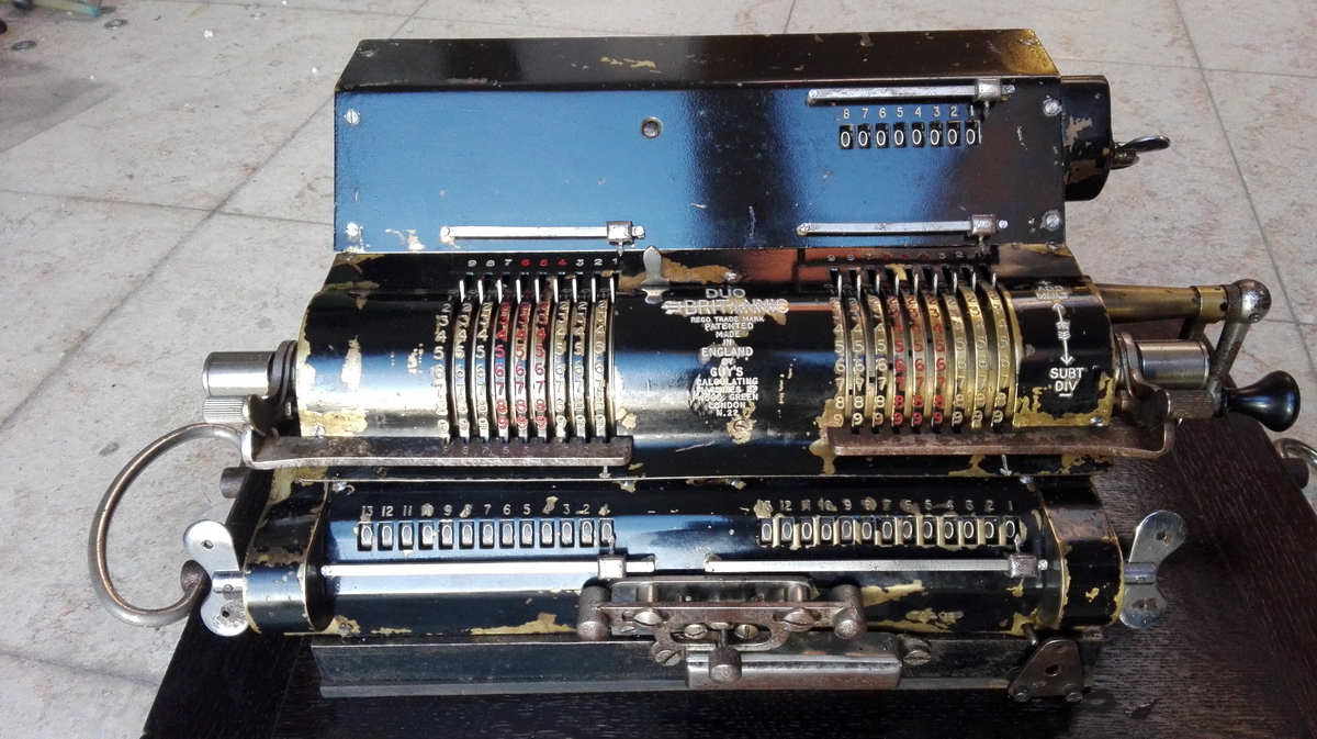
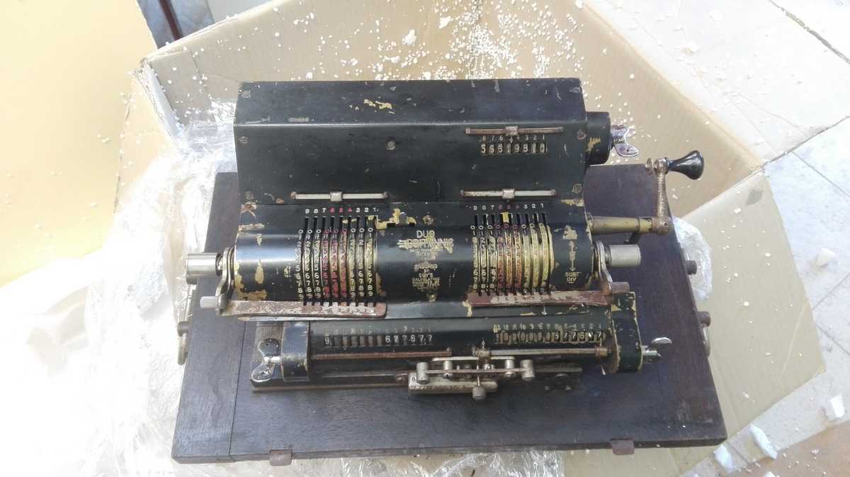
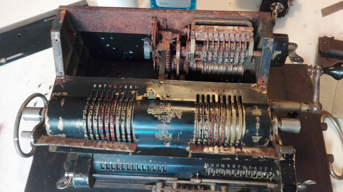
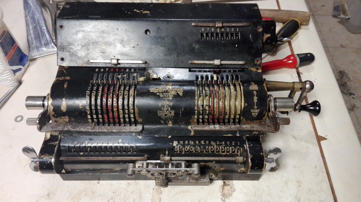
Duo Britannic
So this machine is the rarest of the rare - one of the elusive twin Britannics that were built at the beginning of World War 2, in an attempt to replace the German Brunsviga double calculators that could no longer be imported, but were necessary for artillery calculations. Unfortunately, Britannic didn't get it entirely right according to the British army, and instead Block and Anderson was contacted in 1942 to pair up American Marchant machines into double calculators. Alan Turing had one of these, and it is currently at the Manchester Museum of Science and Industry.
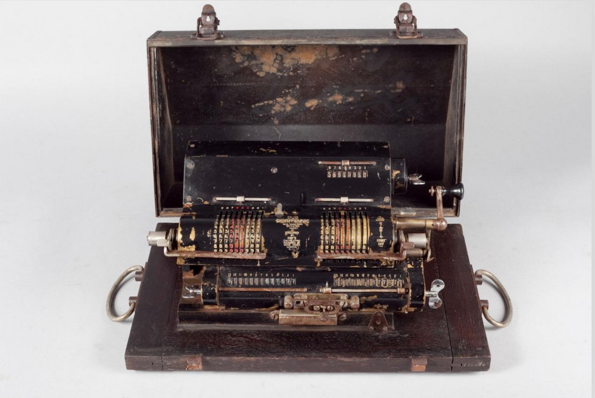
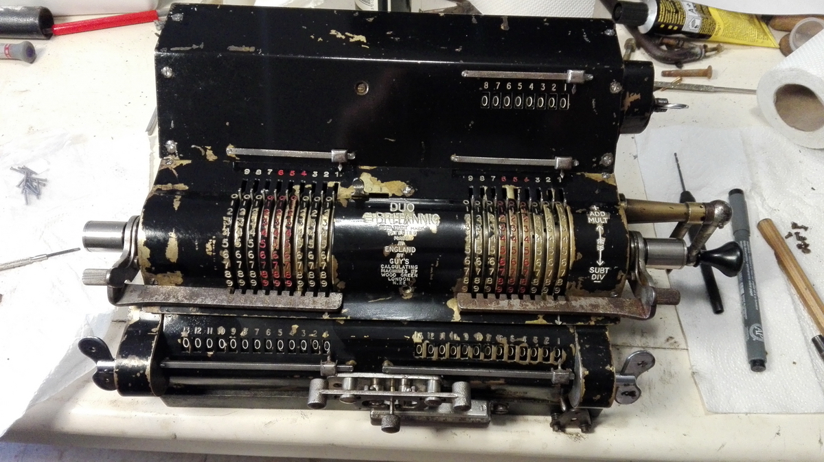
Image courtesy of the seller, Salvaged Ltd.
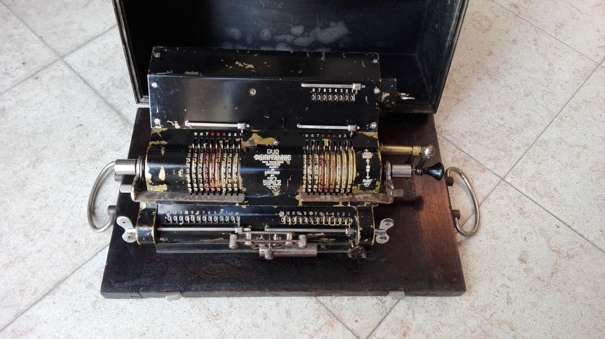
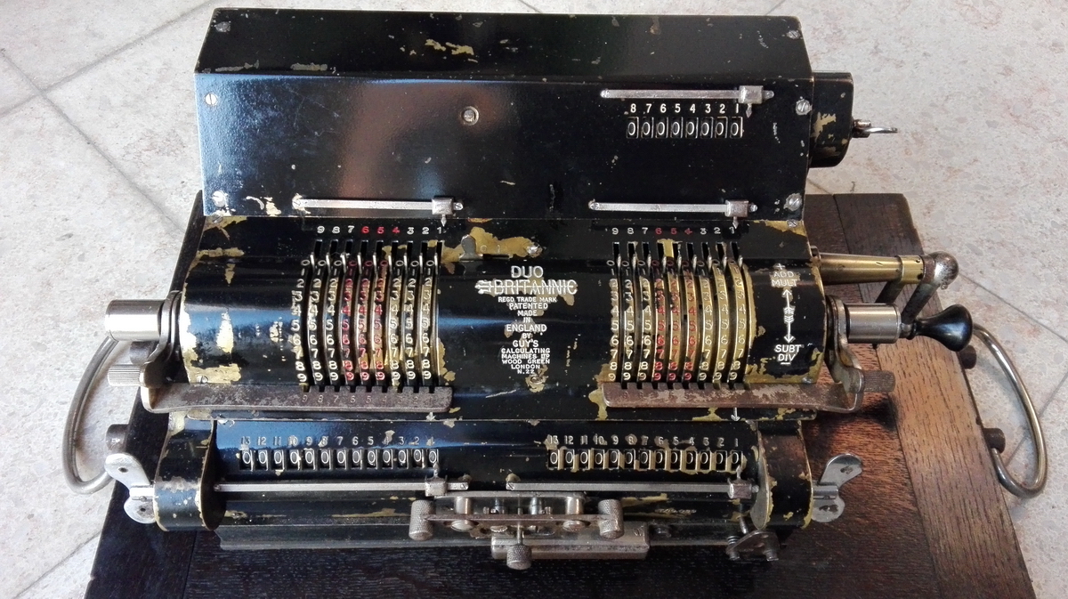
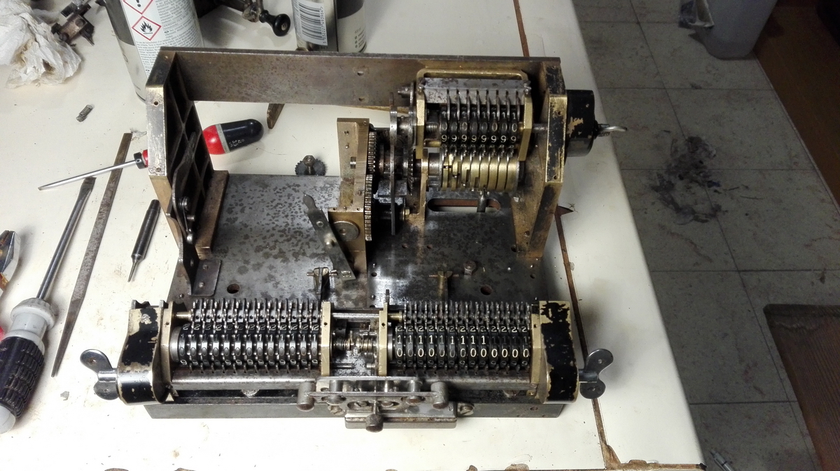
So when people started emailing me that this machine had appeared on ebay, I couldn't believe my luck - it was the last brand of double calculator missing from my collection. Clearly, it was blocked, because the handle was pointing up at an awkward angle, but this is usually quite easy to remedy. So I bought it, and at a very reaonable price at that.
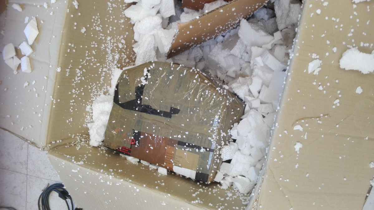
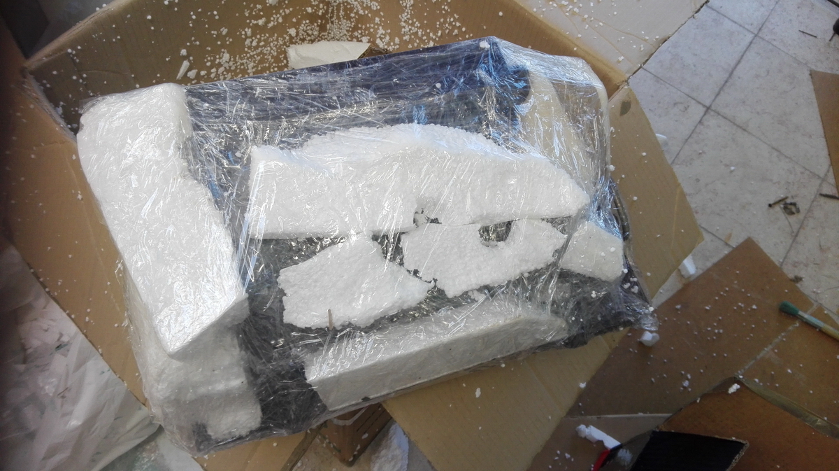
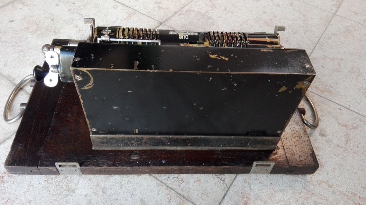
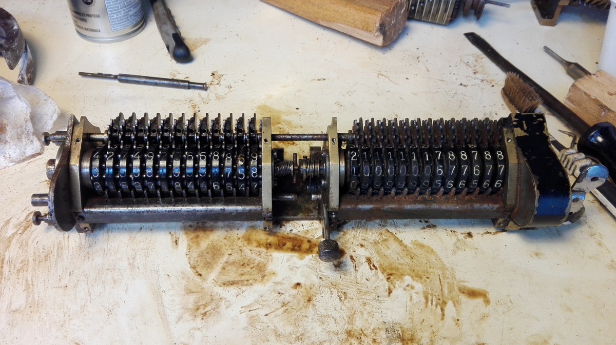
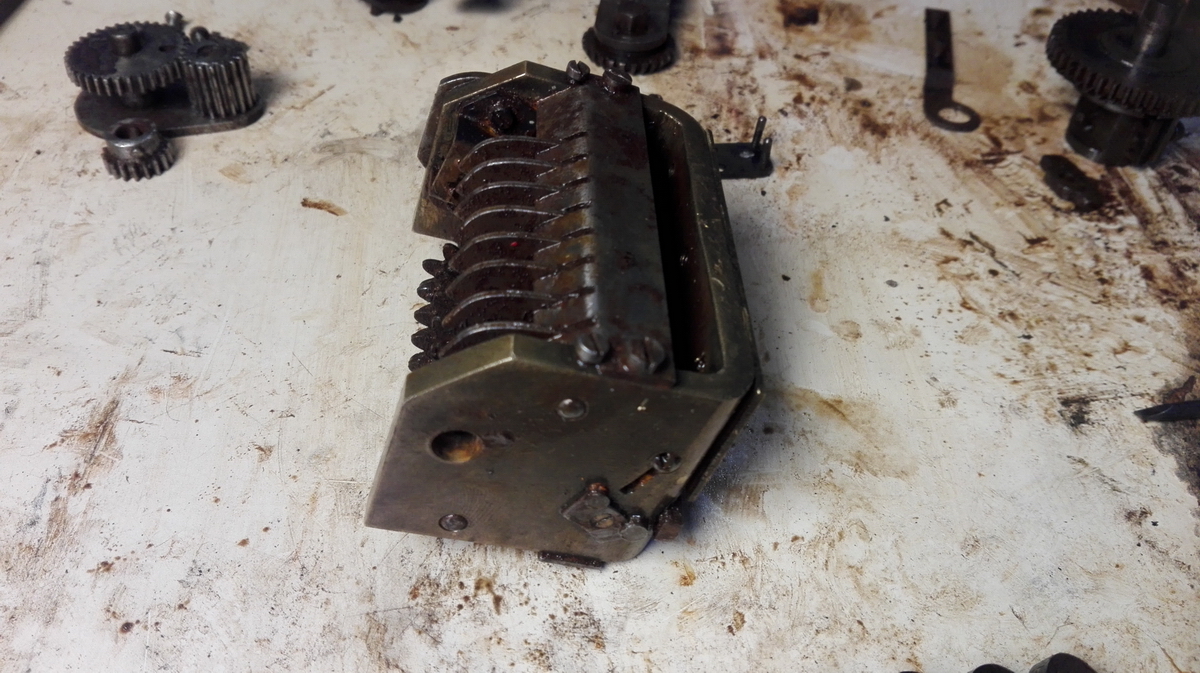
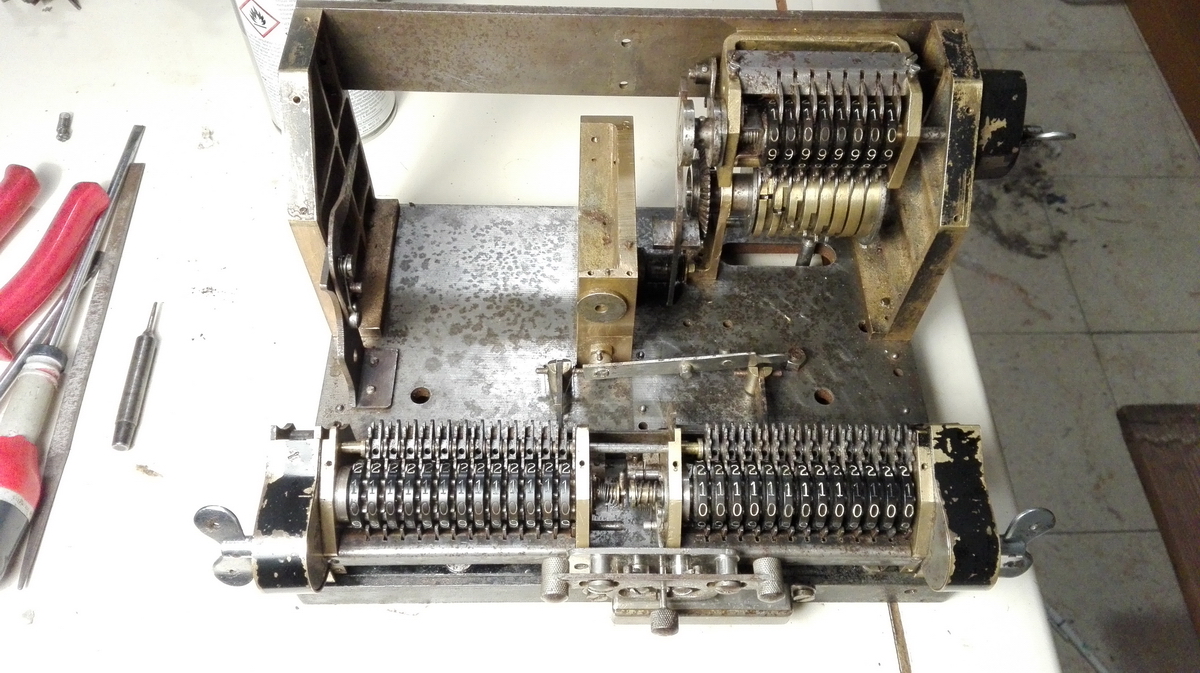
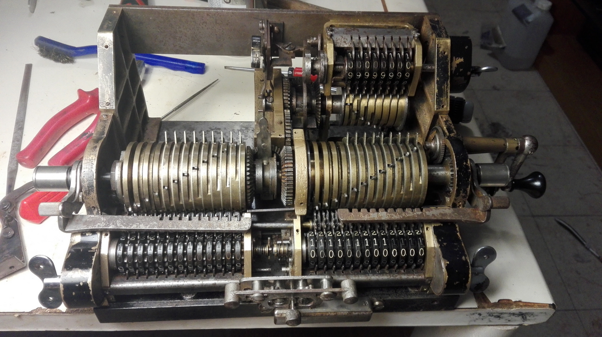
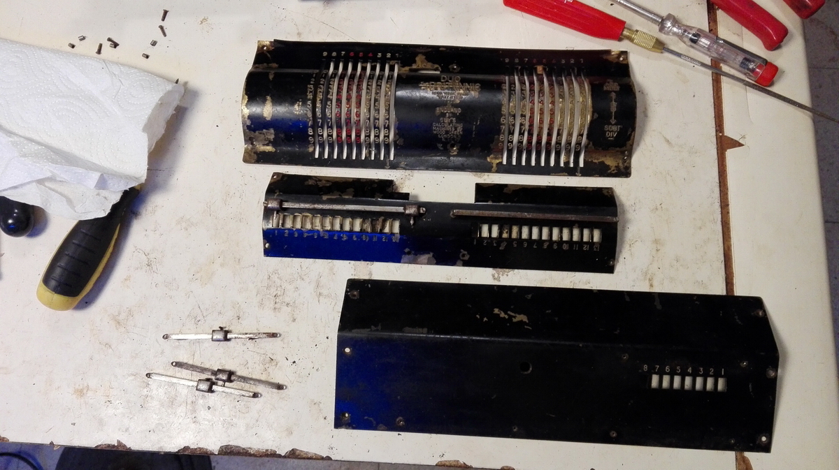
When it arrived, a week later, very carefully wrapped, I unpacked it, and noticed that it was not "just" blocked, it was completely frozen solid - there wasn't even a tenth of a millimeter of movement anywhere - not in the crank, not in the clearing butterflies, not in the carriage, nowhere. It was as though the machine had been cast as a single piece.
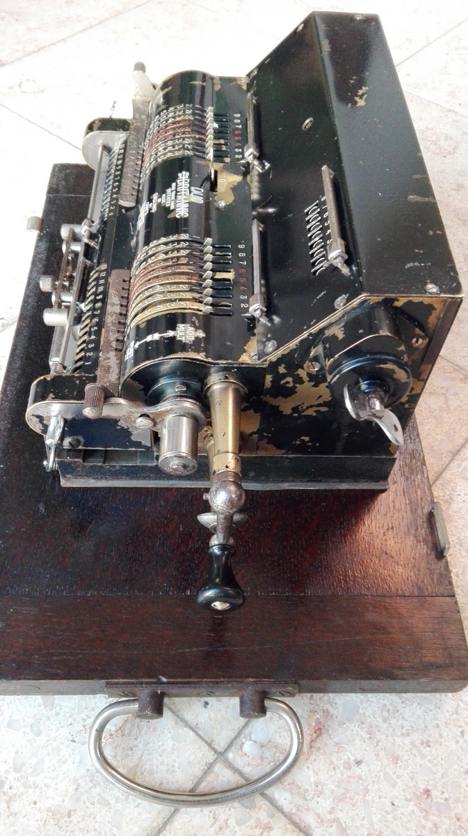
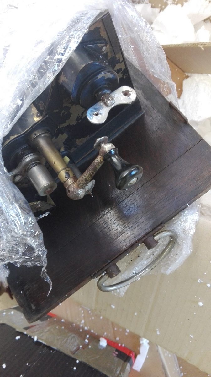
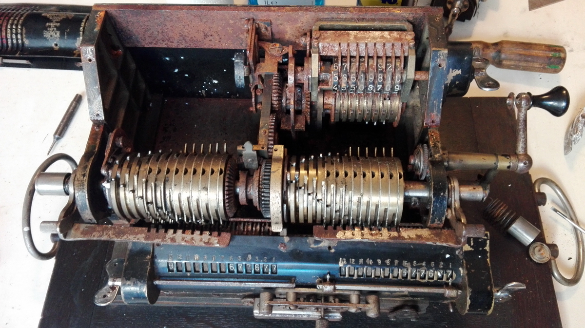
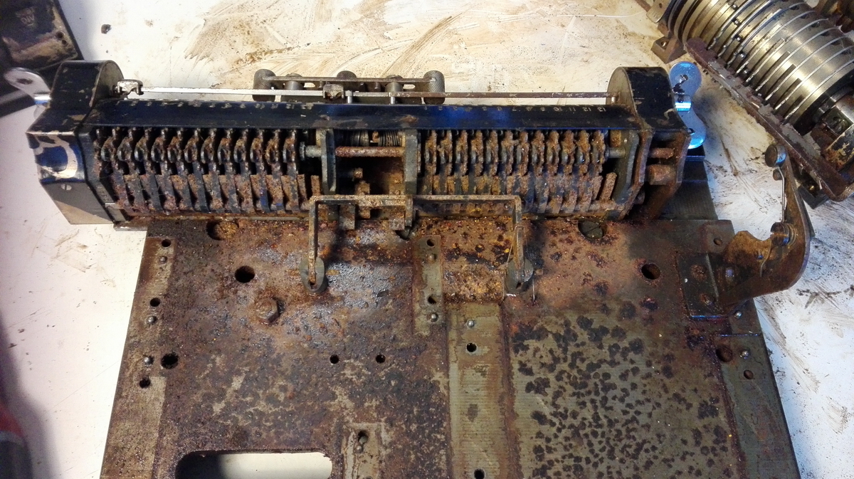
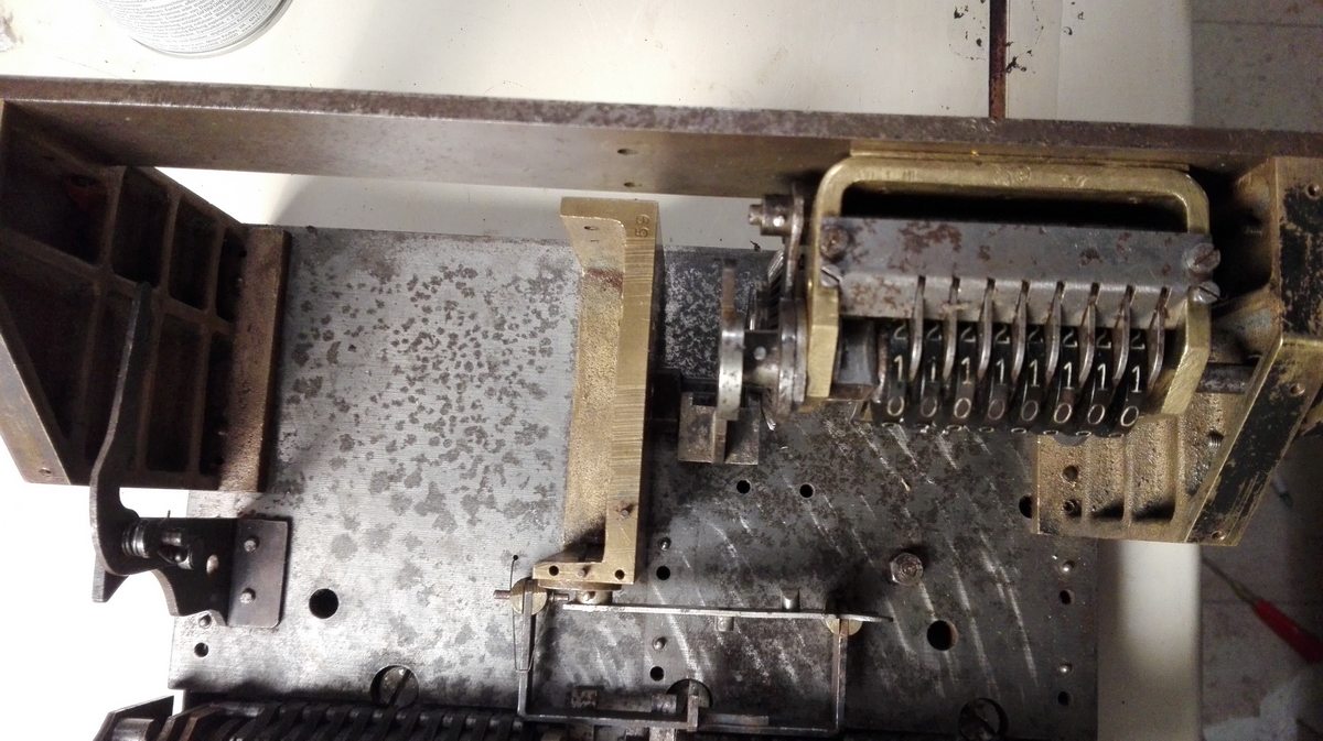
Taking the top off, it was immediately clear why this was - the machine had suffered from water ingress, and was completely, totally, utterly rusted solid. It looked like something that had been sitting on the main deck of Titanic since 1912.
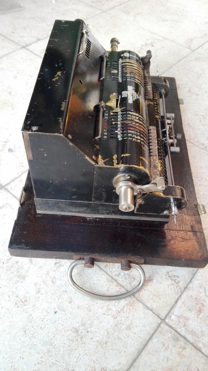
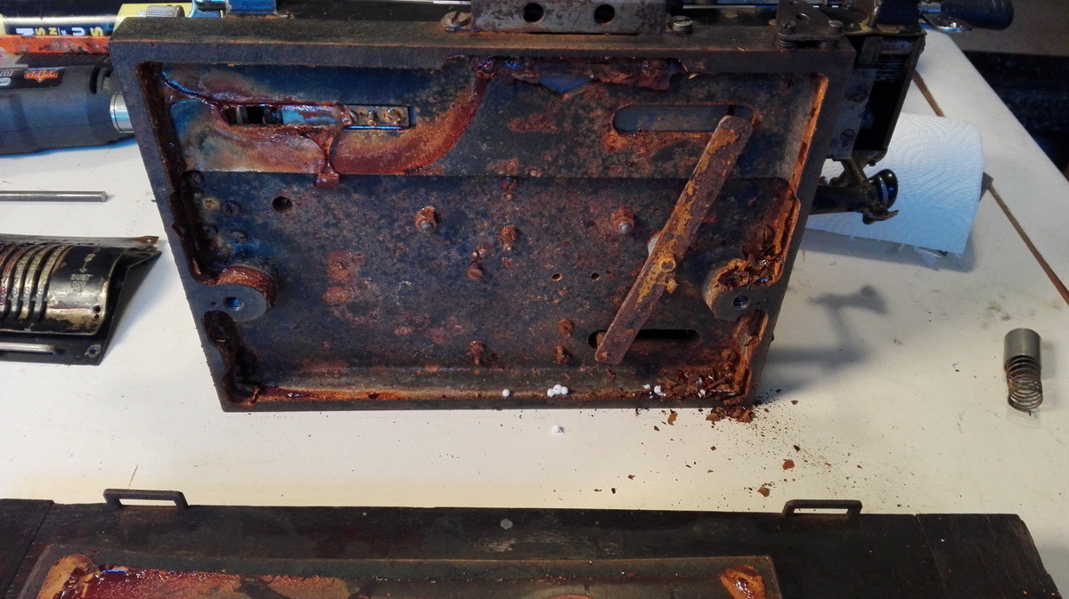
The reason for this was also clear. The machine is mounted on a wooden baseboard. Wood is somewhat permeable to water, so if water gets into the machine for one reason or other, the water can slowly get out. In this case however, Britannic decided to put a rubber slab between the metal machine baseplate and the wood.
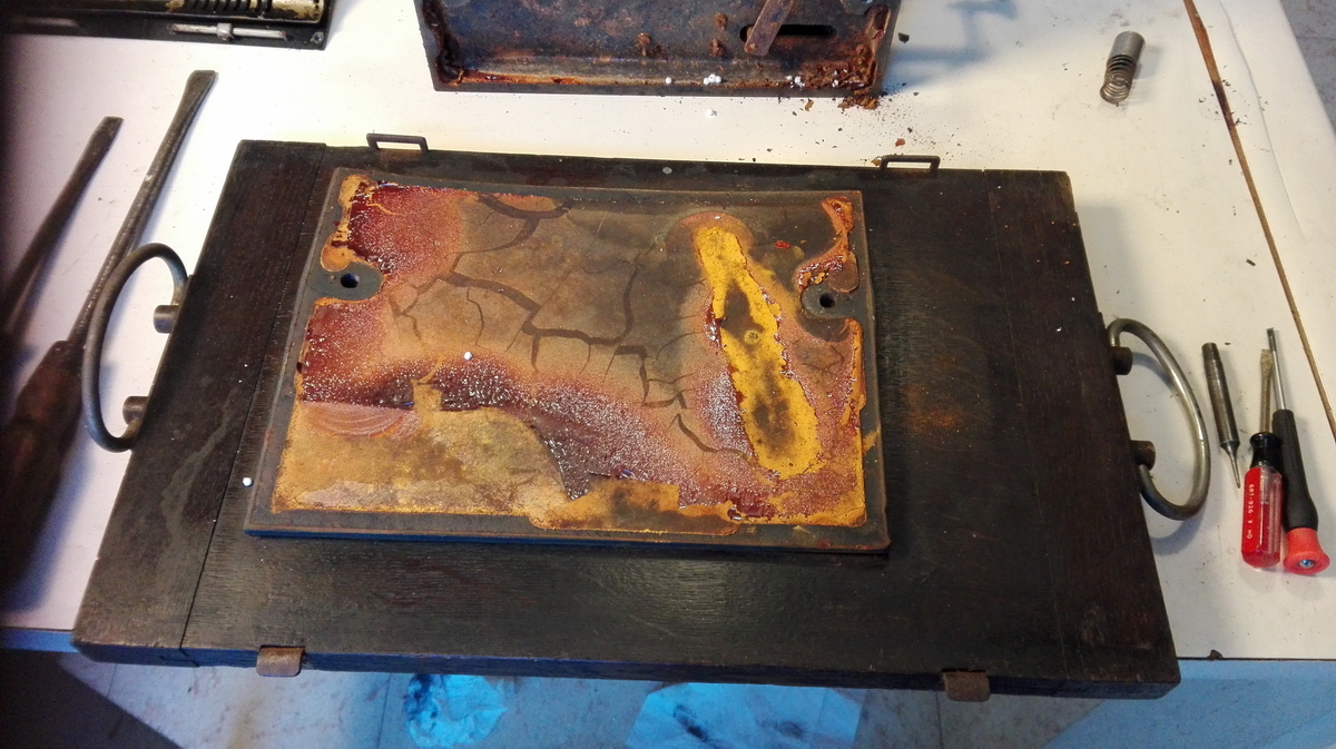
Water that runs down into the cavity under the baseplate on top of the rubber can only distill out of the machine through the slot that feeds up into the machine housing, where it can condense everywhere and rust everything, before finally escaping through the input slots in the top of the machine. They should never have put the rubber in there, and this wouldn't have happened ... or at least it wouldn't have been so bad.
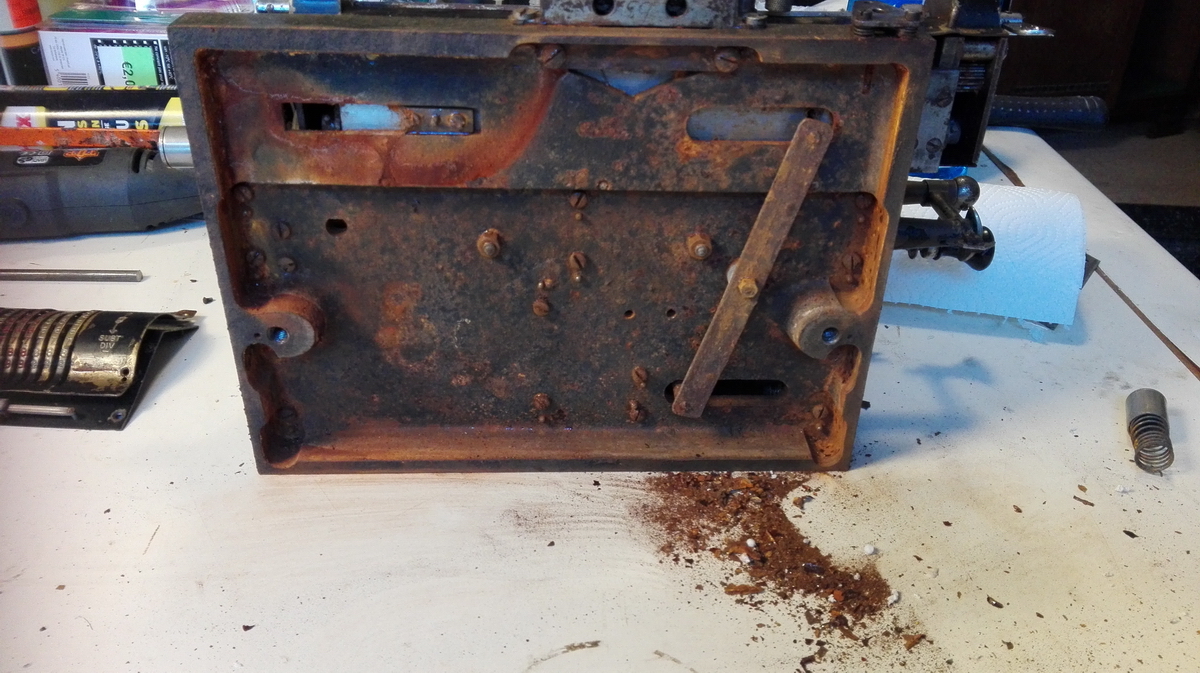
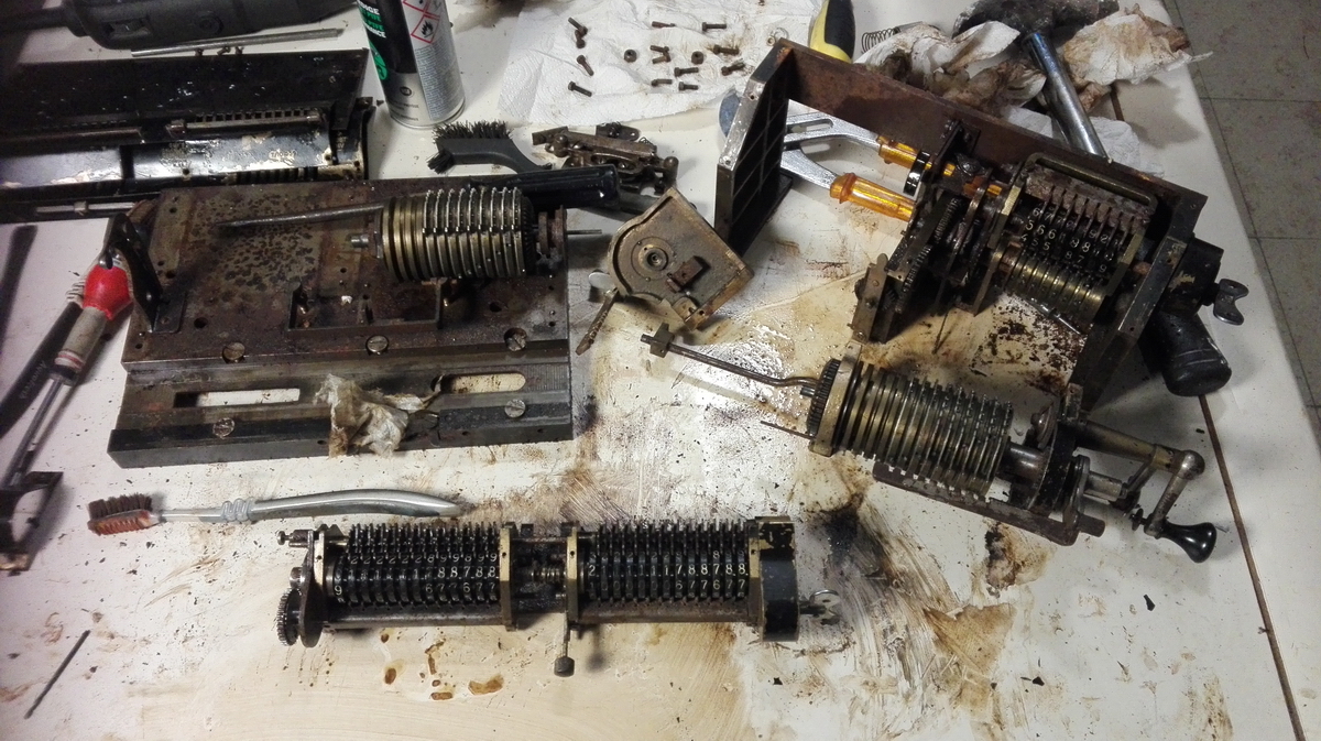
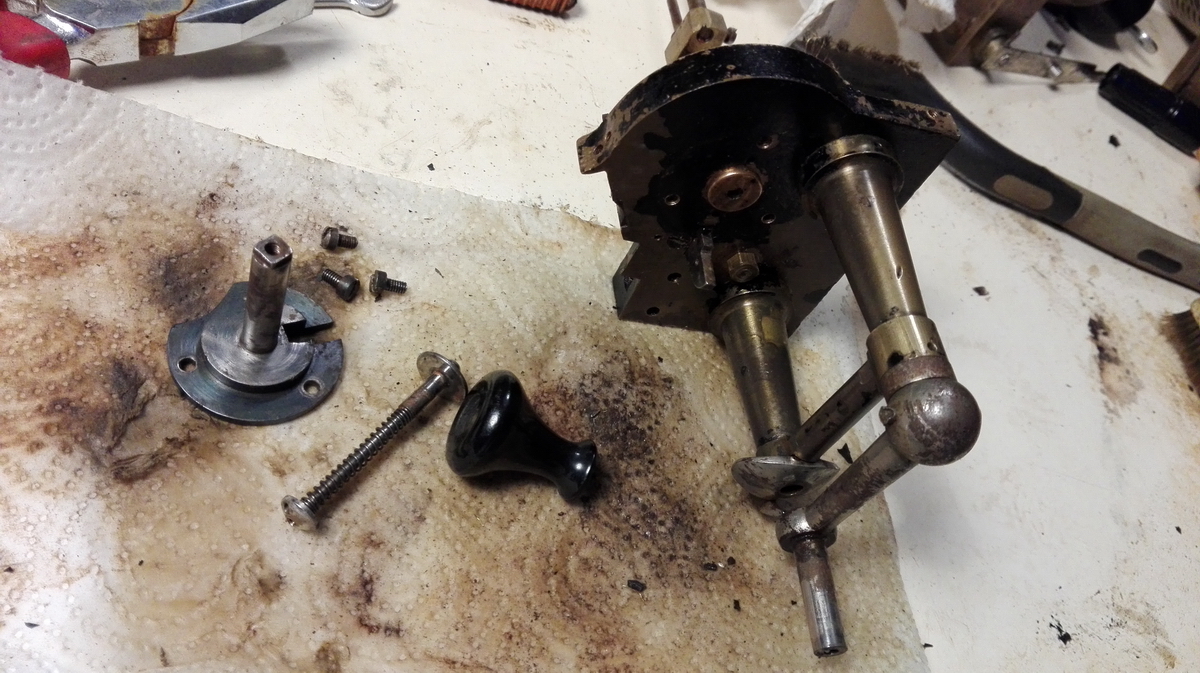
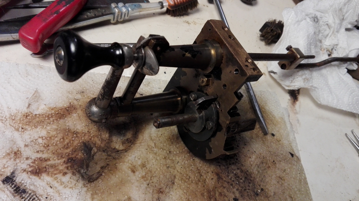
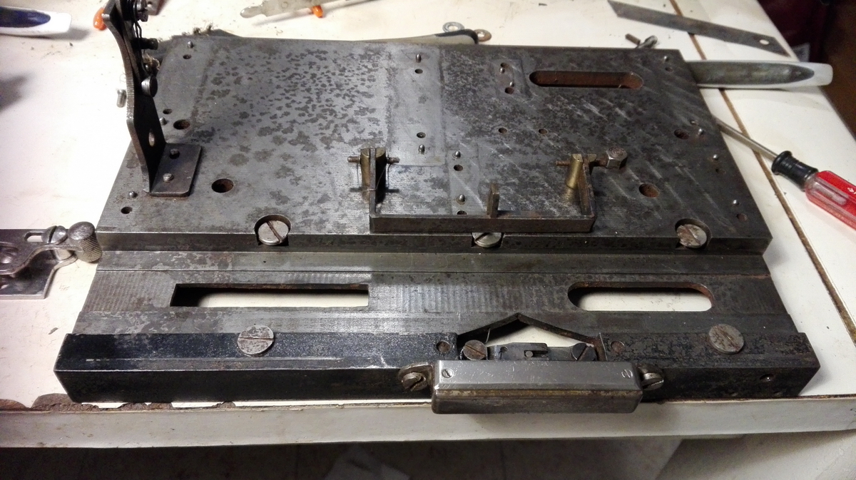
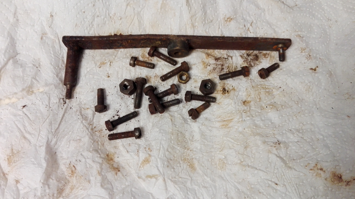
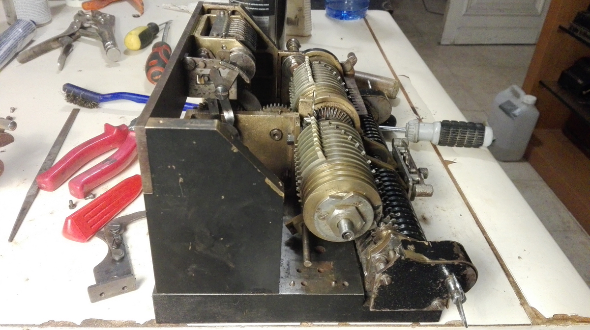
Generally, disassembly starts by putting the machine in its rest position, and then sliding the carriage out. In this case, that would obviously not work, because everything was stuck. The only way forward would be to undo all the screws at the bottom of the calculator, and lift the entire machine off the baseplate, in order to then free up the carriage and slide it out. After liberal application of penetrating oil, the screws put up a bit of a fight, but I didn't destroy any screw heads - I just broke one screw head clean off. In the end everything came out, the machine came off the base plate, then the carriage loosened up and came off, as well as the tabulator.
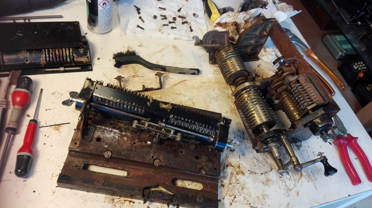
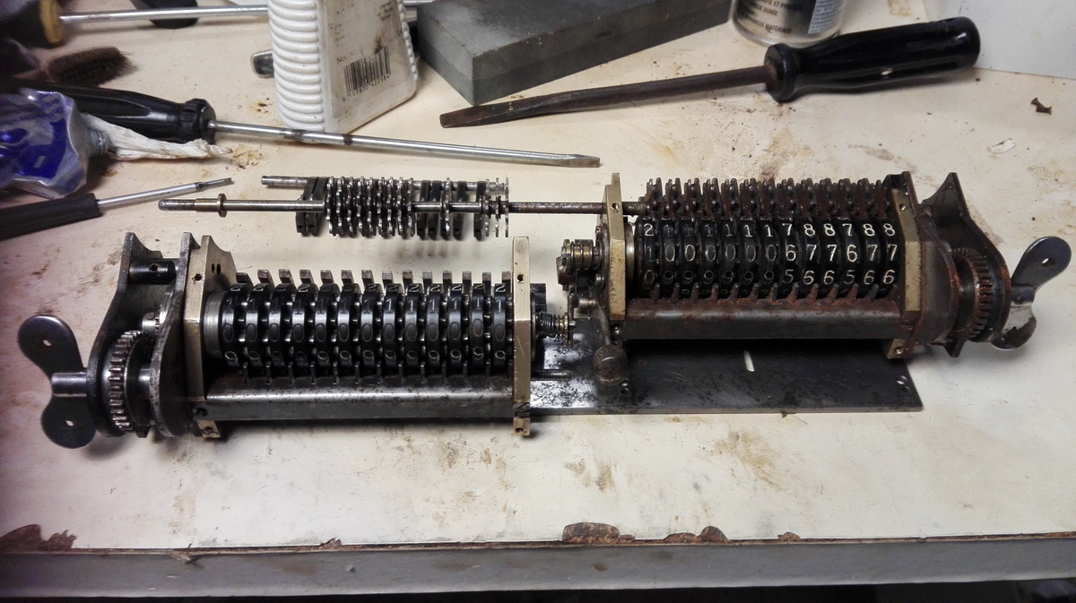
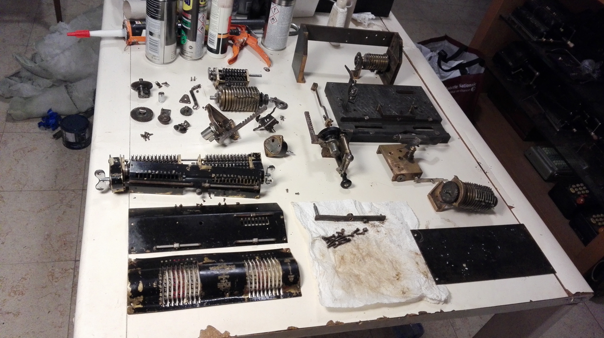
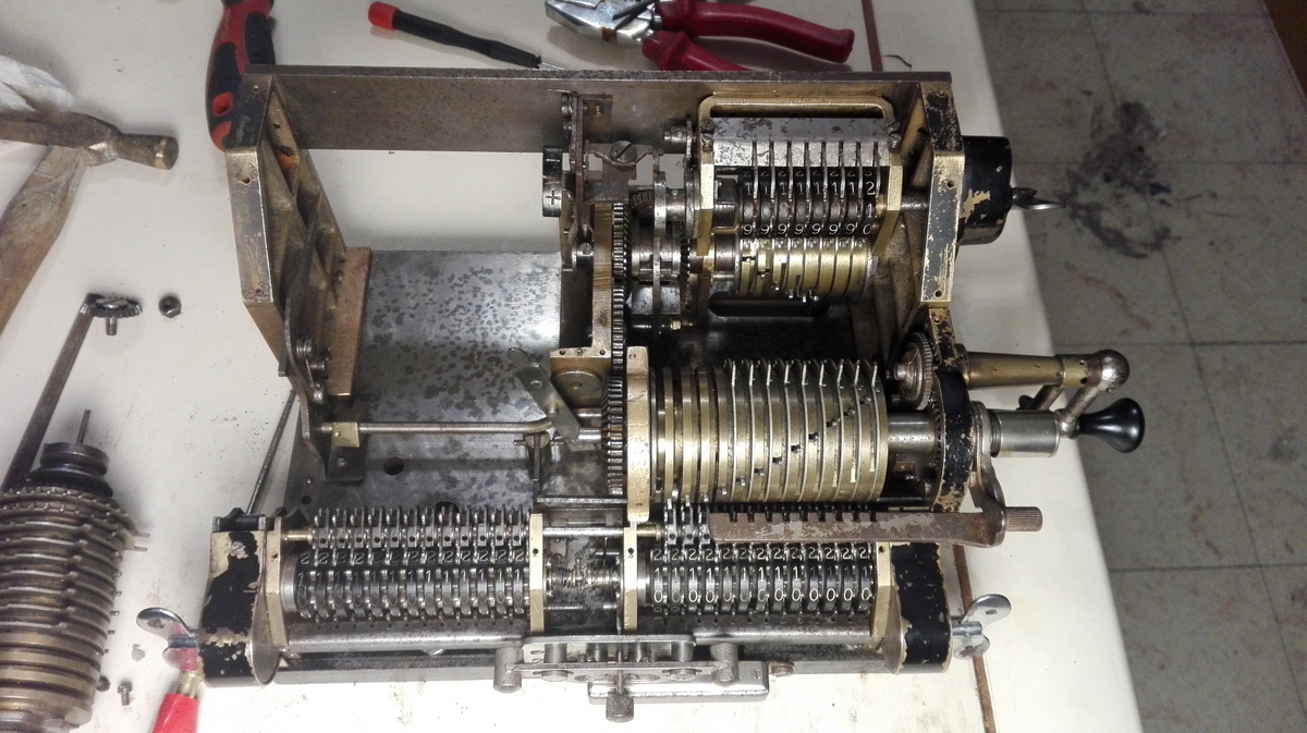
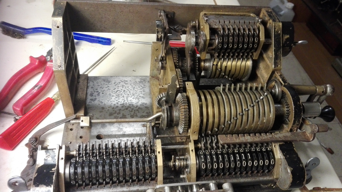
The damage to the machine is a bit strange in the sense that the rust really, really locks everything - everything that should rotate on an axle is completely stuck. But when you use force to break the bond, as soon as the part starts turning, there is hardly any damage to the surfaces, and after they are cleaned up and lubricated, the part turns just as before, without slop. This gives me some hope that it will be possible to rescue the machine. The biggest issue for now are the counting works - true to form, every gear, pawl and tens' carry arms has solidly rusted into place. The next part of the restoration is disassembling these and cleaning the rust off everything. The key to keeping the oversight in a restoration is to only disassemble one subassembly at a time. So the machine was taken apart into large chunks - the baseplate, the carriage, the left and right and center uprights with the pinwheel cylinders, and the back of the machine with the gearing for the counter and the counter itself.
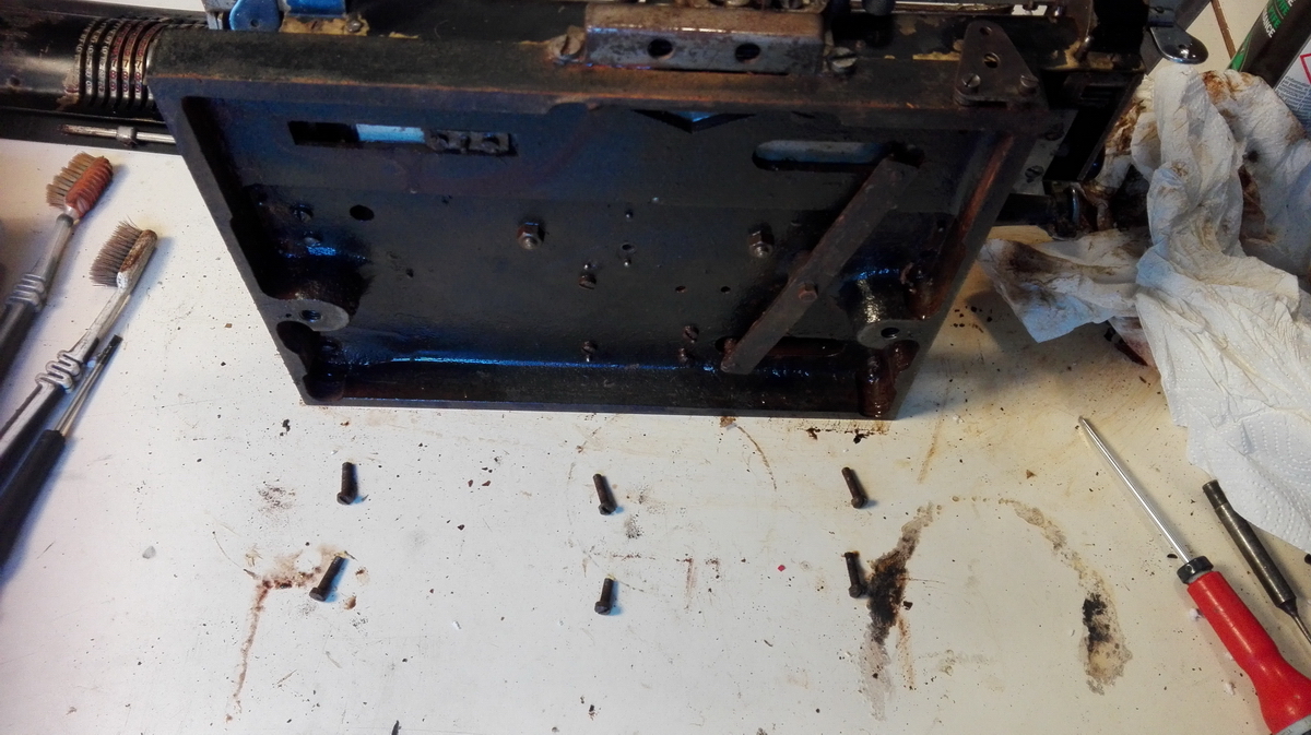
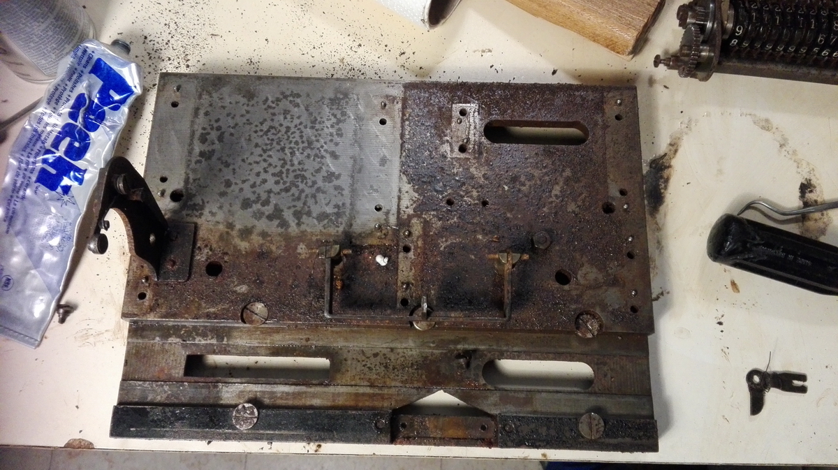
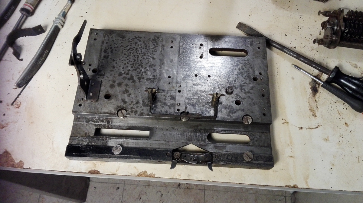
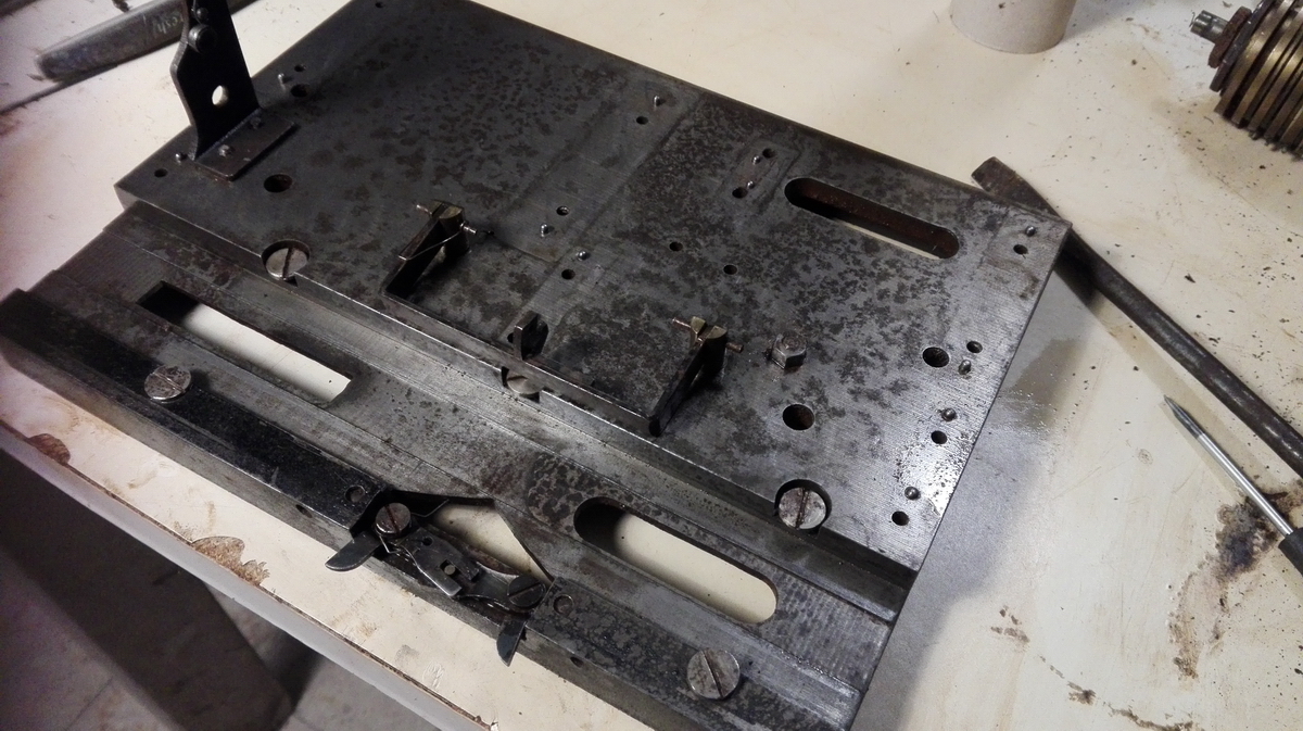
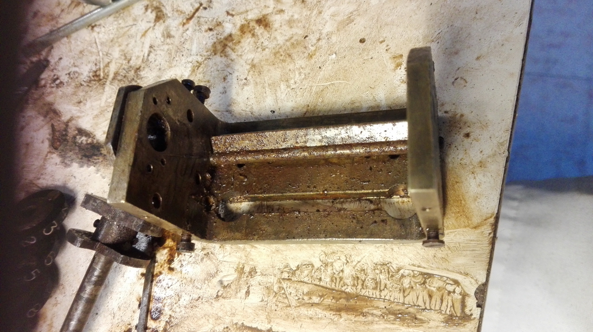
I decided to start with the baseplate. A bit of steel wool, a scraper and metal polish made quite the transformation:
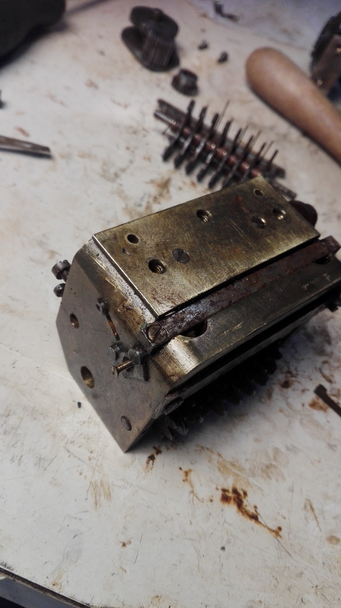
Next up - the carriage, and there also, one assembly at a time. I tackled the left result register first. The main issue with the carriage is with the clearing system used by Britannic, the clearing teeth are not fixed solidly to the axle, which would then have to move laterally to engage and disengage them with the counter wheels. Instead, the teeth sit on a long key, which slides left and right in a keyway in the axle. It doesn't take much imagination to see where the problem is - 8 cm of key and keyway + rust = problem. I started by cleaning up and lubricating the outside of the left result register.
It quickly became clear that it would have to come off the baseplate, but unfortunately, the axle holding the tens carry levers in place is continuous through both result registers. If you're only trying to work on one at a time, this is not conducive to progress ... in any case, the baseplate screws were taken out.
Then the whole result register was lifted off its locating pins and the axle through the tens carry levers broken loose, so the whole register could rotate around this. Eeew!
A bit of clean-up, but it is obvious that it will need further disassembly.
Tens' carry levers and intermediate gears off, pins on either side of the main axle knocked out and all the ancillaries taken off either end of the main axle. Now I could finally break it loose, and lubricate the key and keyway, which eventually also gave up and started moving.
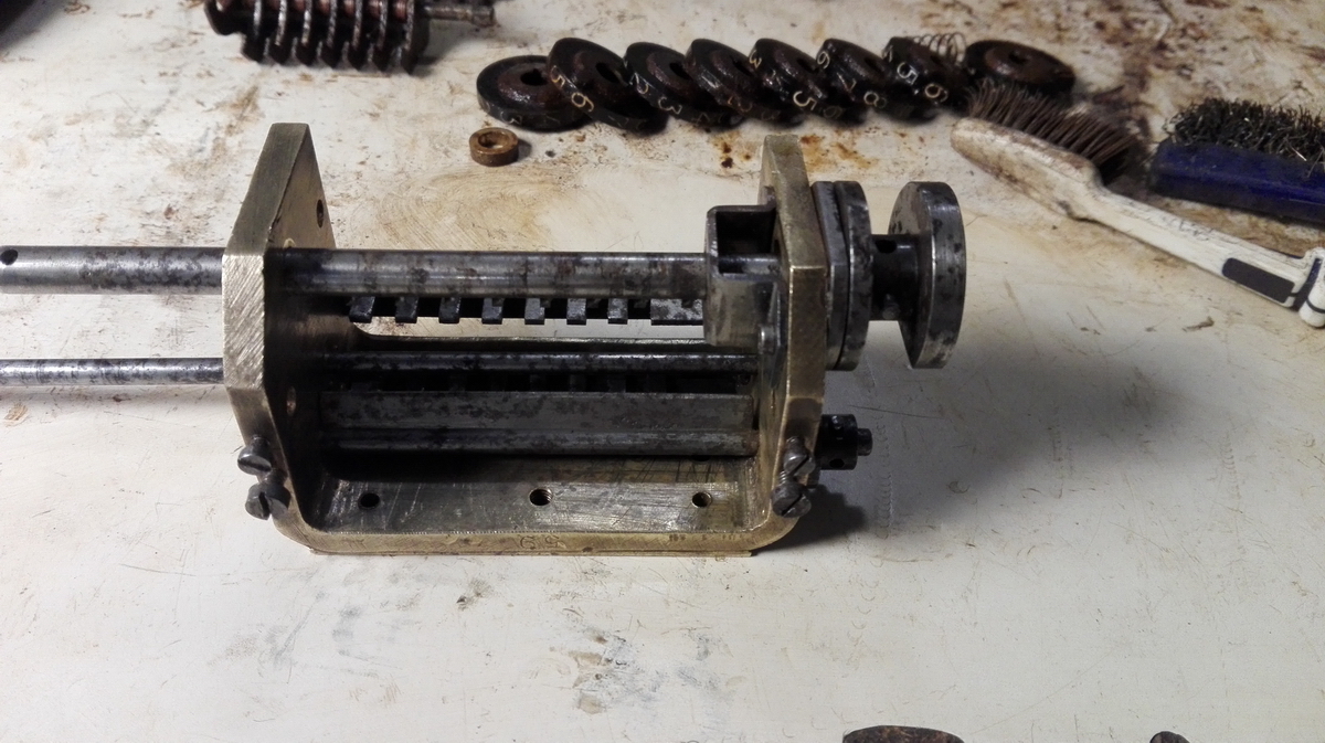
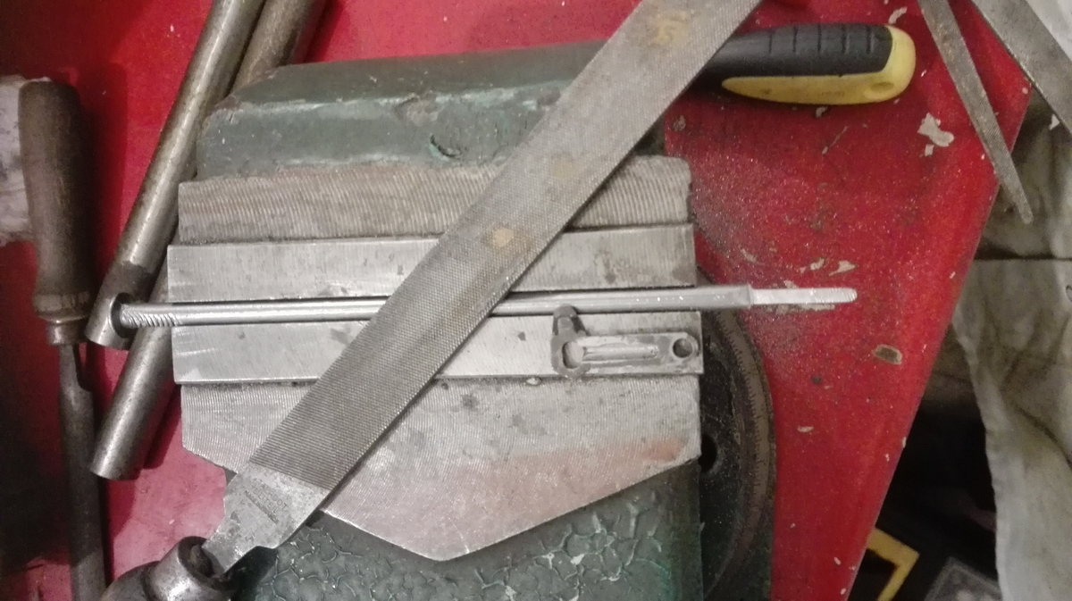
So then finally the whole thing could be disassembled and cleaned:
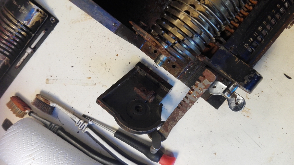
This is during reassembly, and the first clear picture of what the key and keyway in the main axle look like.
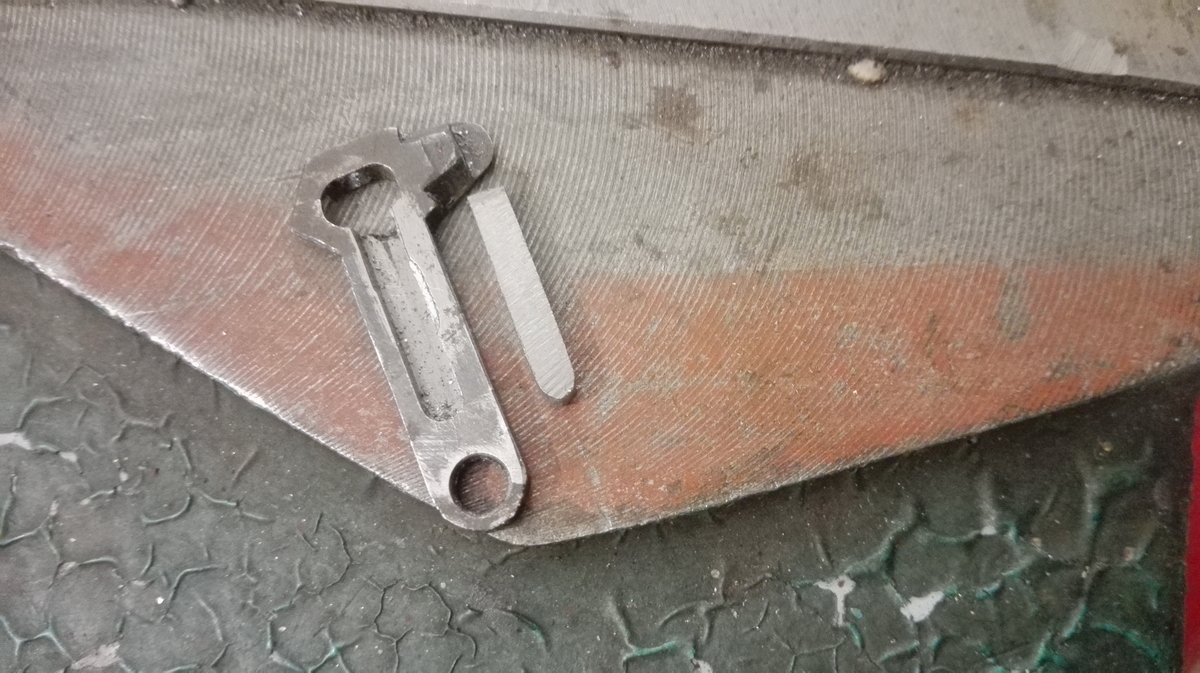
The way the clearing works is that the key, captive in the keyway which rotates with the main axle on clearing, is pushed to the right by this ramp on the left end of the carriage
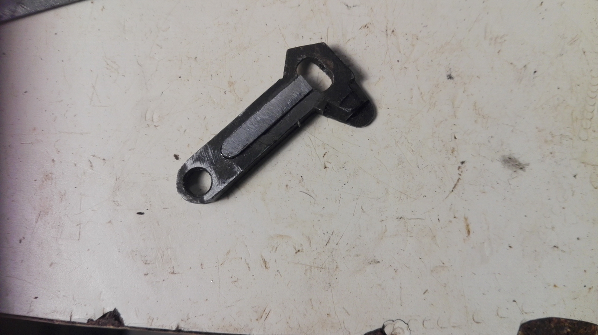
It then drags along all the numeral wheels to 0, and then snaps back to the right because the end of the keyway is spring-loaded by the washers and spring which are pinned in place at the right end of the carriage, as can be seen in this view of the left result register re-assembled - minus the tens carry arms and intermediate gears, because they are on a common shaft with the right result register.
Comparison view ... the left register is also off the baseplate now.
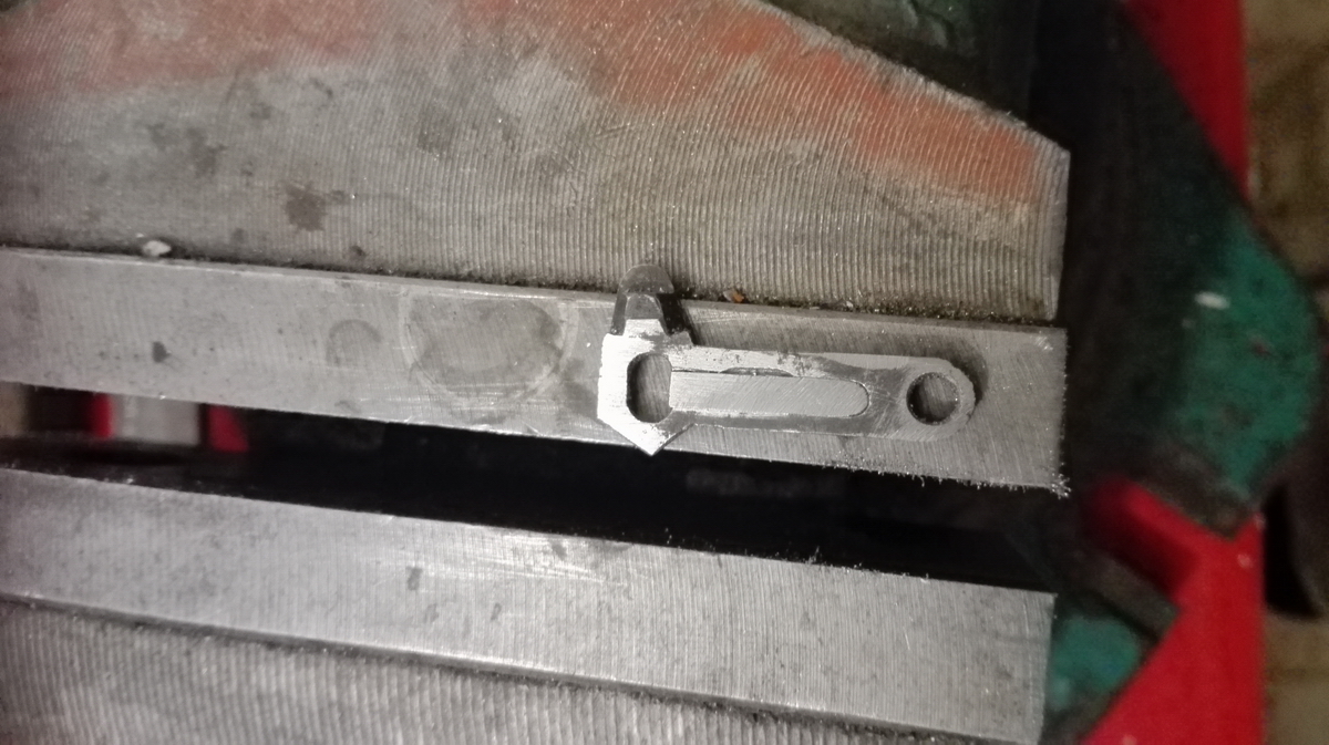
And then we just start over on the right side ...
This already looks a little cleaner ...
Once the right counter is back together as well, it can be mounted on the baseplate, the clearing gear trains installed, and the clearing tested.
If all is well, we can start assembling the tens' carry levers and intermediate gears. They are all on a very long, thin steel rod, that runs through both counters, and can not be inserted with both clearing assemblies in place - so one comes back out, and we start threading gears and tens' carry arms onto the rod. The first six or so can be done by hand, but then the resistance becomes too large for manually twisting the rod, and we have to use light taps with a wooden hammer to get it to move.
Slowly but surely everything is threaded in place - you always have to press down the spring loaded locator pin in the bistable assembly, and then line up the crest of the pin with the rod that has to pass through ... but once in a while it will go wrong, and you let go of the pin - and then you feel it whizzing by your face followed by a faint "clink" somewhere behind you 1.5 seconds later, as it hits the floor the somewhere in the workshop ... the next thirty minutes are then spent looking under everything and carefully cleaning up and swiping the entire workshop floor, until the escape-happy pin is finally located ... I haven't really lost one just yet (touch wood).
So that's the carriage assembly back together.
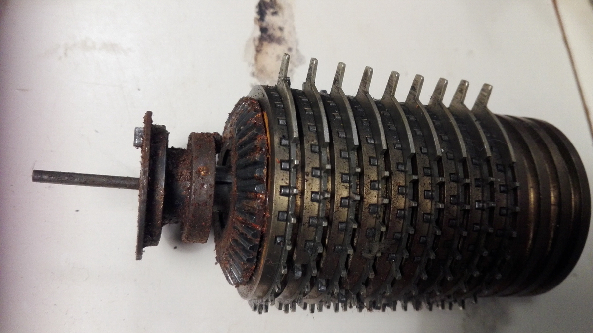
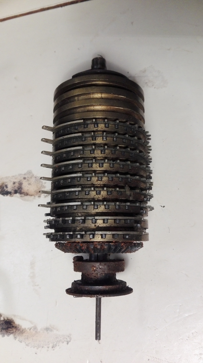
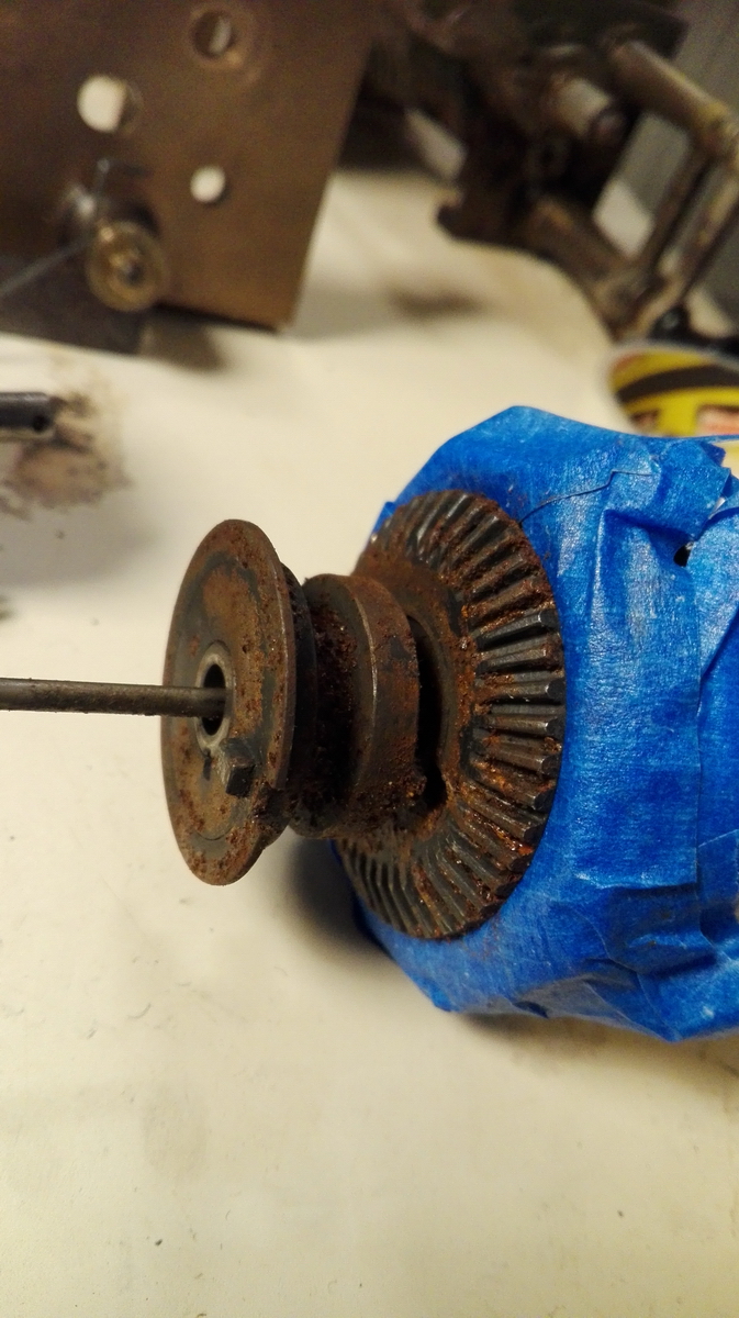
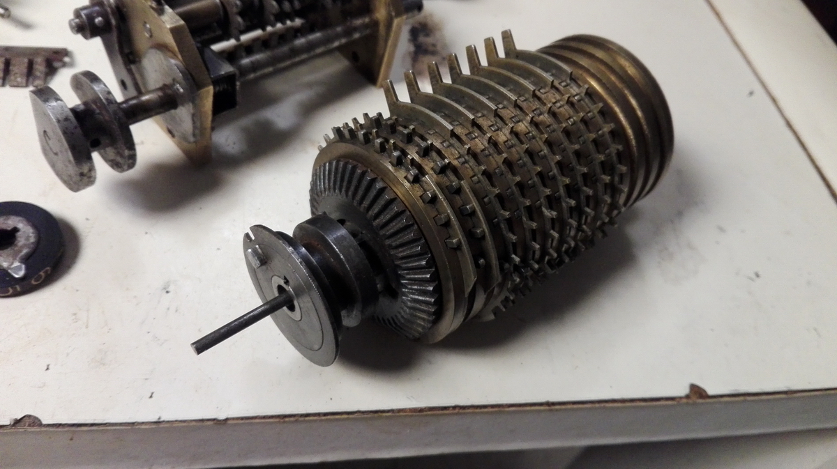
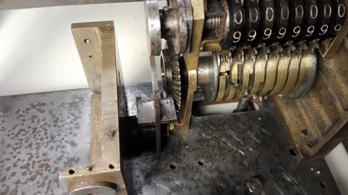
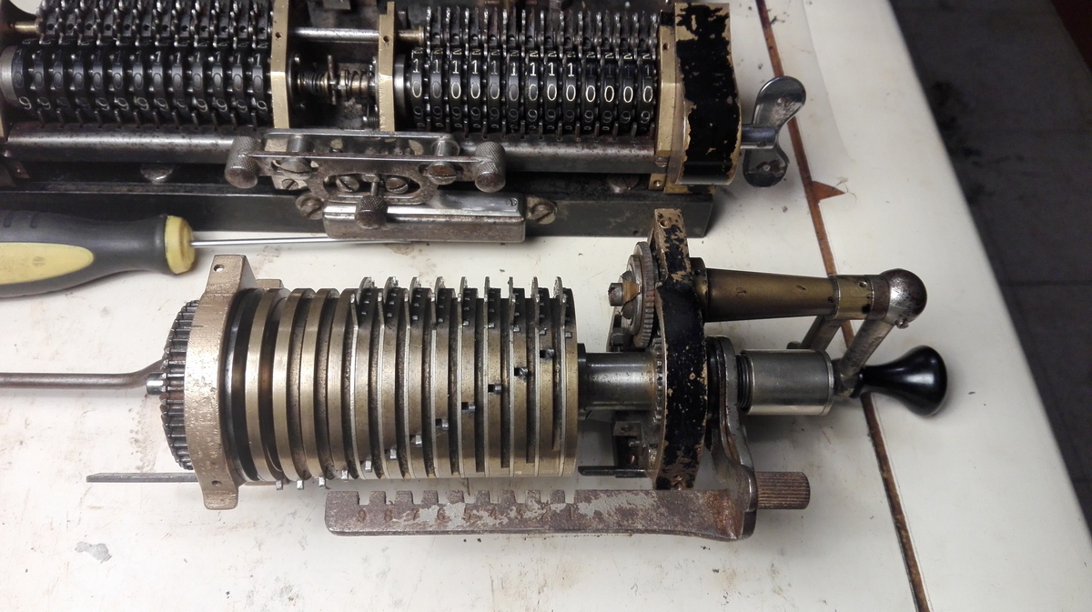
The good news is that the pinwheel cylinders that came out of the machine work fine - once liberated from the death grip of the rust on all the machinery around them, they can be set and rezeroed over their entire range, so at least this will not be a worry - I won't be disassembling pinwheel cylinders. The main reason is of course they are made chiefly out of brass, which doesn't rust. The steel at the end, with the conical gear for the direction change mechanism, does rust though ...
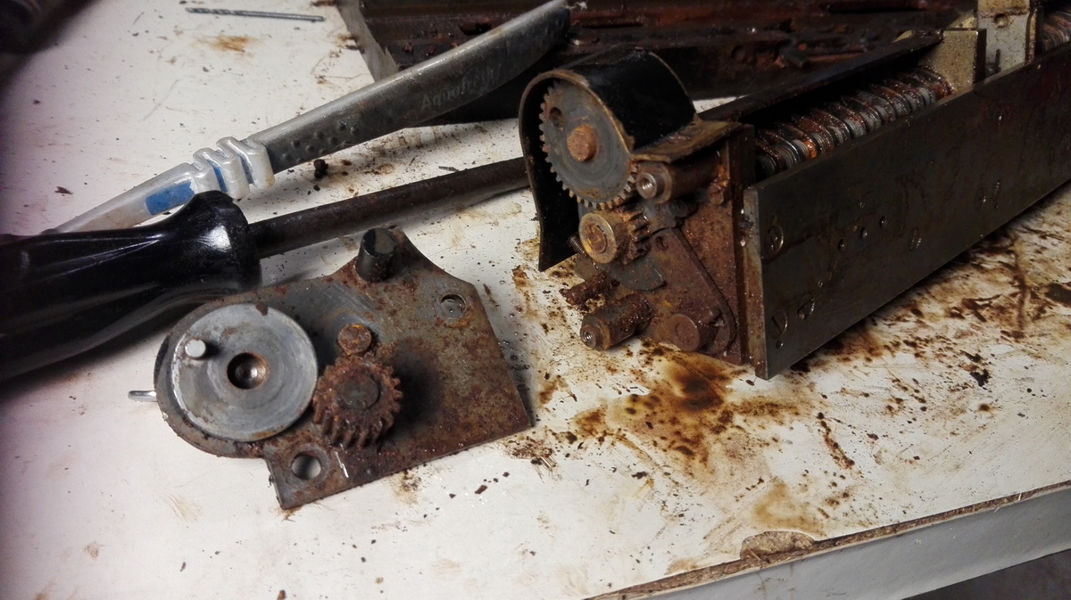
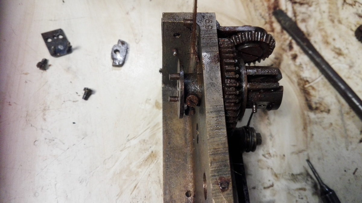
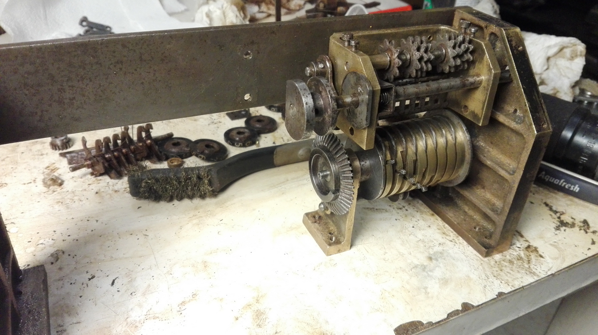
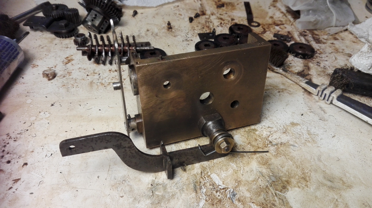
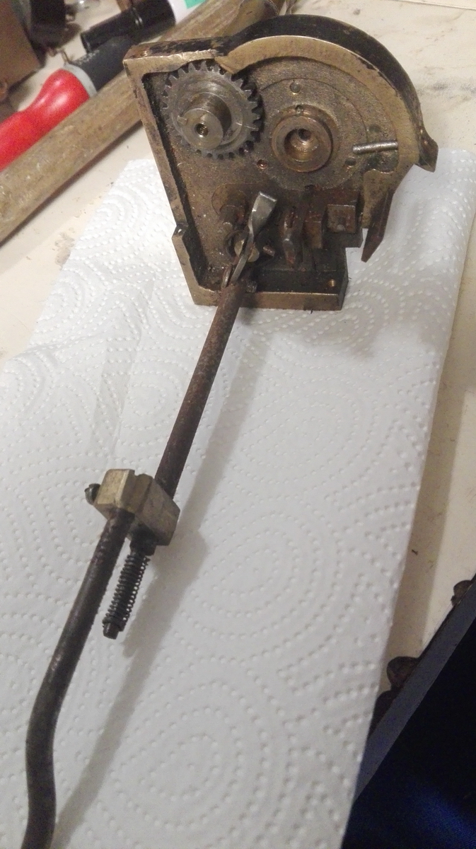
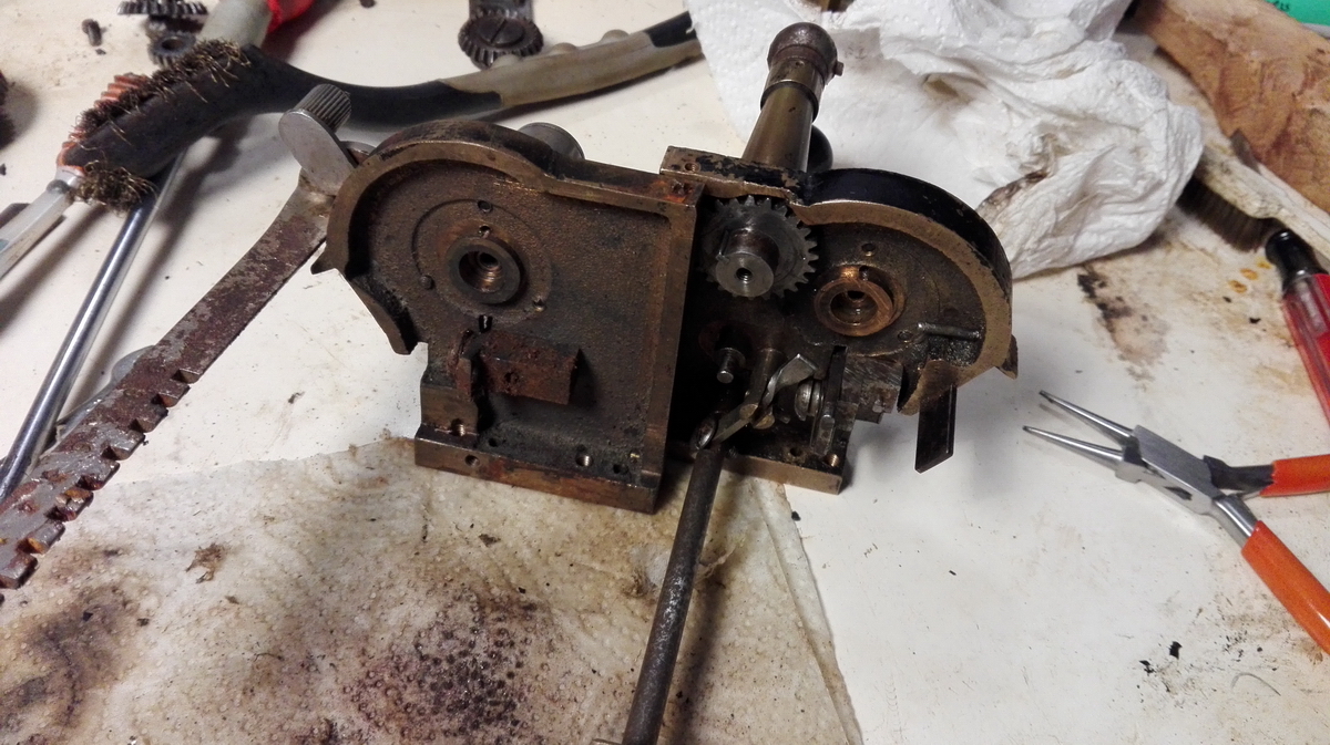
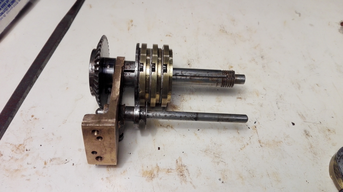
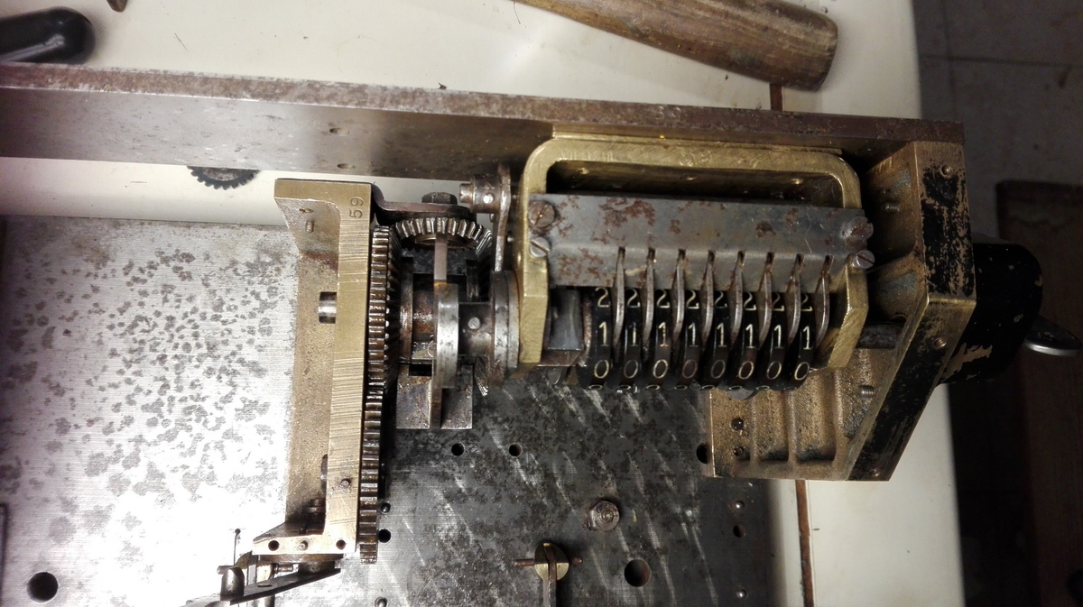
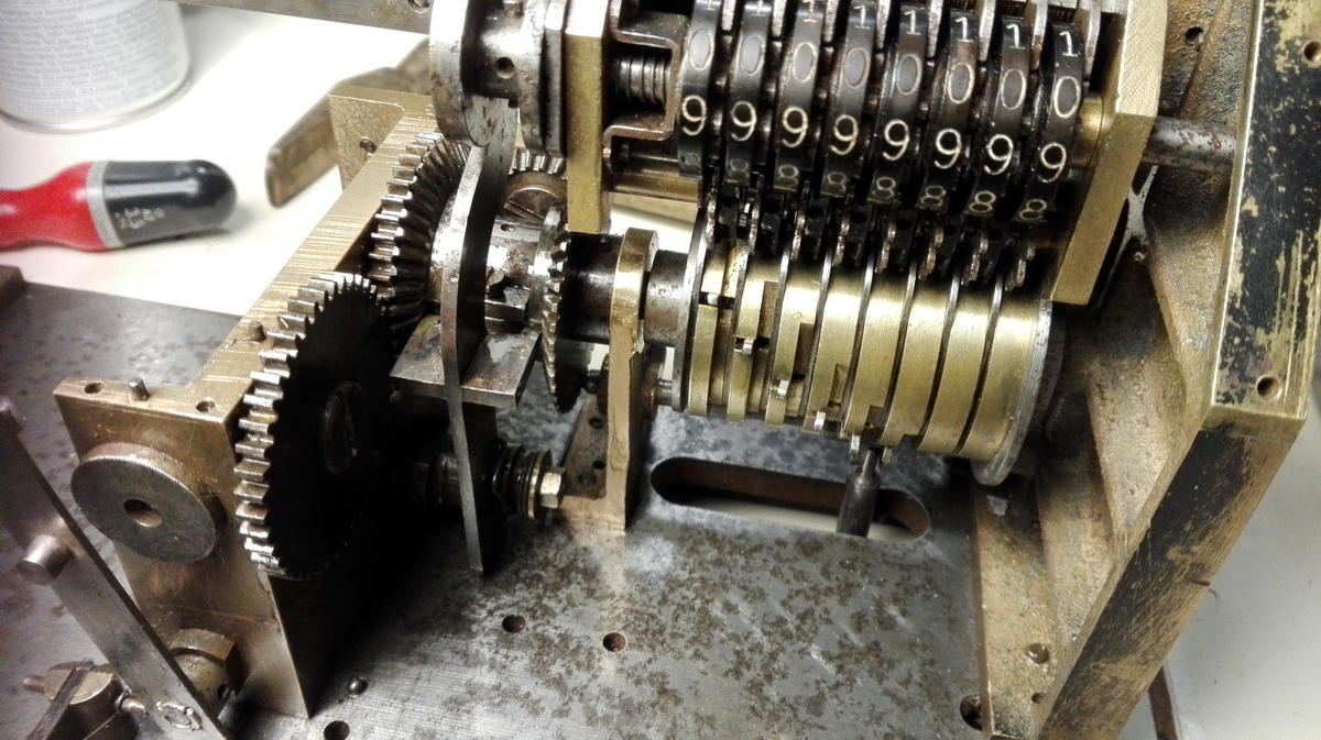
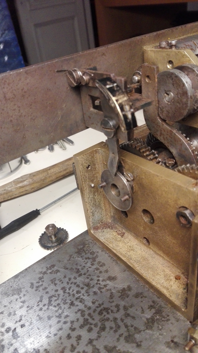
The next point of attention was disassembling the completely rusted counter assembly, and the gear train necessary for making it turn in either direction. This was a bit of a fight, because not all the screws were very accessible, and the shape of the base frame makes it very unstable when trying to put pressure on a screw head to try and break it free. Also, there was even more rust than in the carriage. I did manage to undo the small intermediate gear, and the large gear taking the drive from the right pinwheel cylinder back to the counter assembly.
As you can see, I also undid the clearing, but the gears inside were much more stuck than in the clearing gear trains in the carriage. I had to tap and lever them, and finally use vise-grips to get the large gear to move. In the process, the pin on which this large gear sits came loose, because it was only peened in place from the back. This means the entire assembly had to come off to re-peen it, but to get the assembly off, the small gear from the counter shaft was in the way of the last screw. And the loose pin was in the way of the small end of the cotter pin that held the gear to the shaft - so the counter assembly had to be disassembled first before the clearing could be fully disassembled. Most of the rest of the assembly is screwed to the steel back plate, so this was also the way to disassemble it - undo the screws in the back, to start taking the selector and direction indicator apart. With this out of the way, the central brass support could be slid off the end of the tens' carry drum.
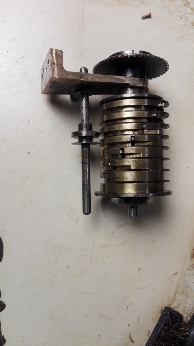
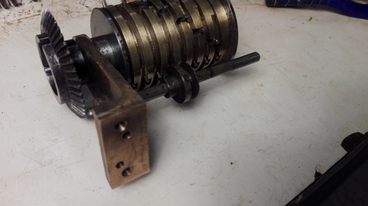
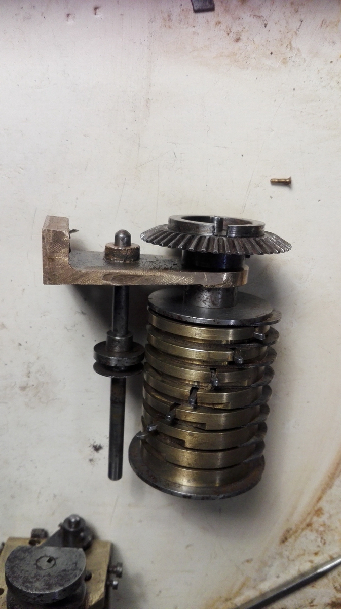
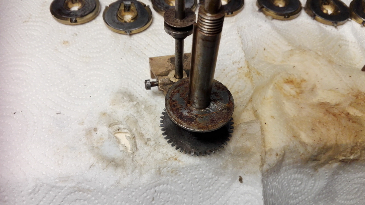
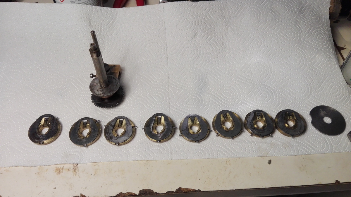
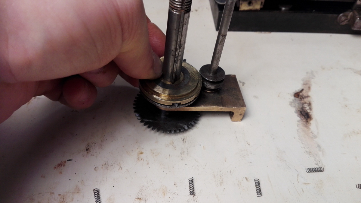
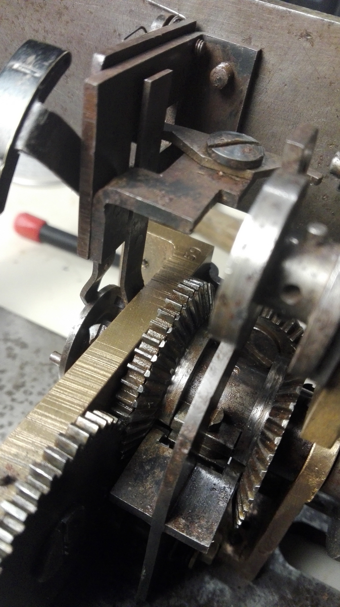
This is it ...
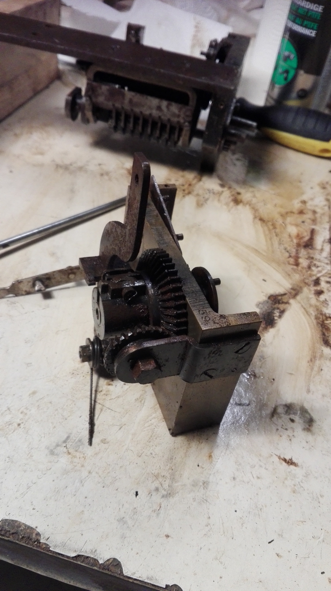
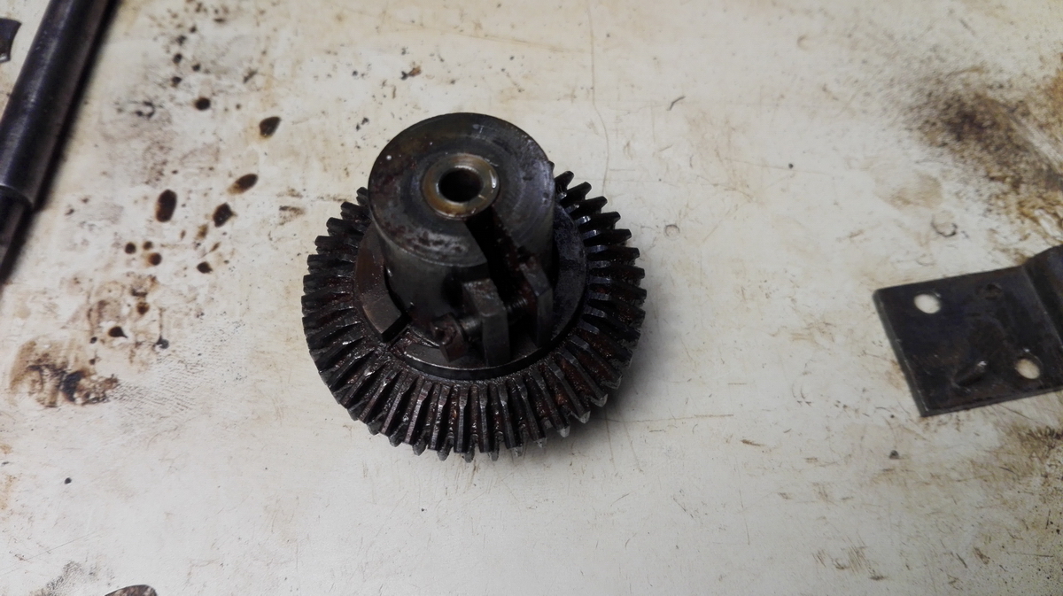
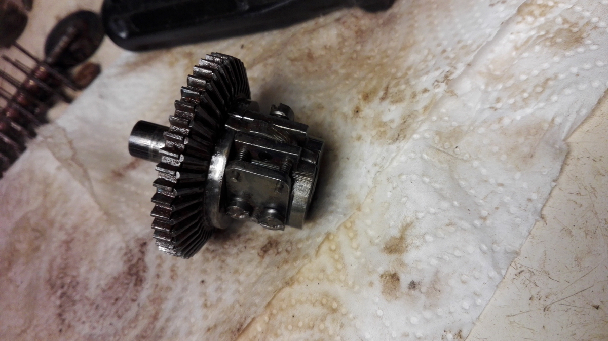
...and this is the direction control.
A steel part looking and acting like a see-saw can locks the conical gear on either side to the axle, thus reversing the direction of the counter and tens' carry drum (in this picture the other conical gear on the right is missing, because it is attched to the tens' carry drum). The conical gear on the left should be able to rotate independently from the straight gear which it sits right next to - but obviously they were intimately rusted together. I honestly can't tell you what I've done to get it free in the end - but apart from copious amounts of penetrating oil, it definitely may have involved bashing with a hammer. I'm not proud of it, but in the end it did work!
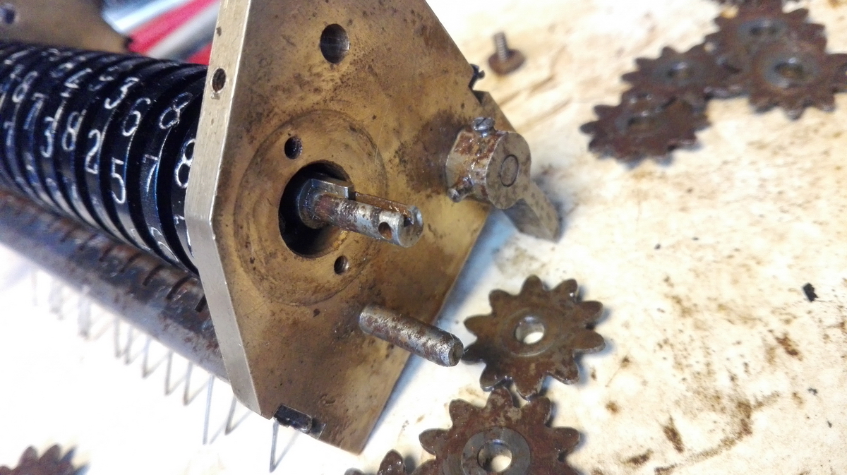
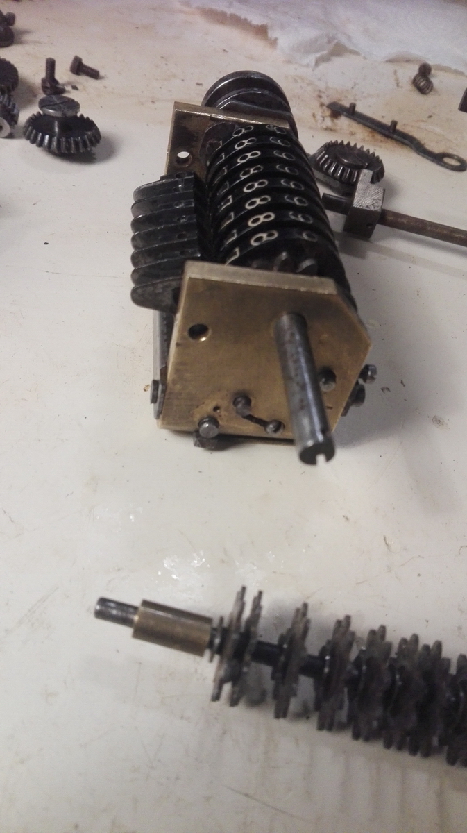
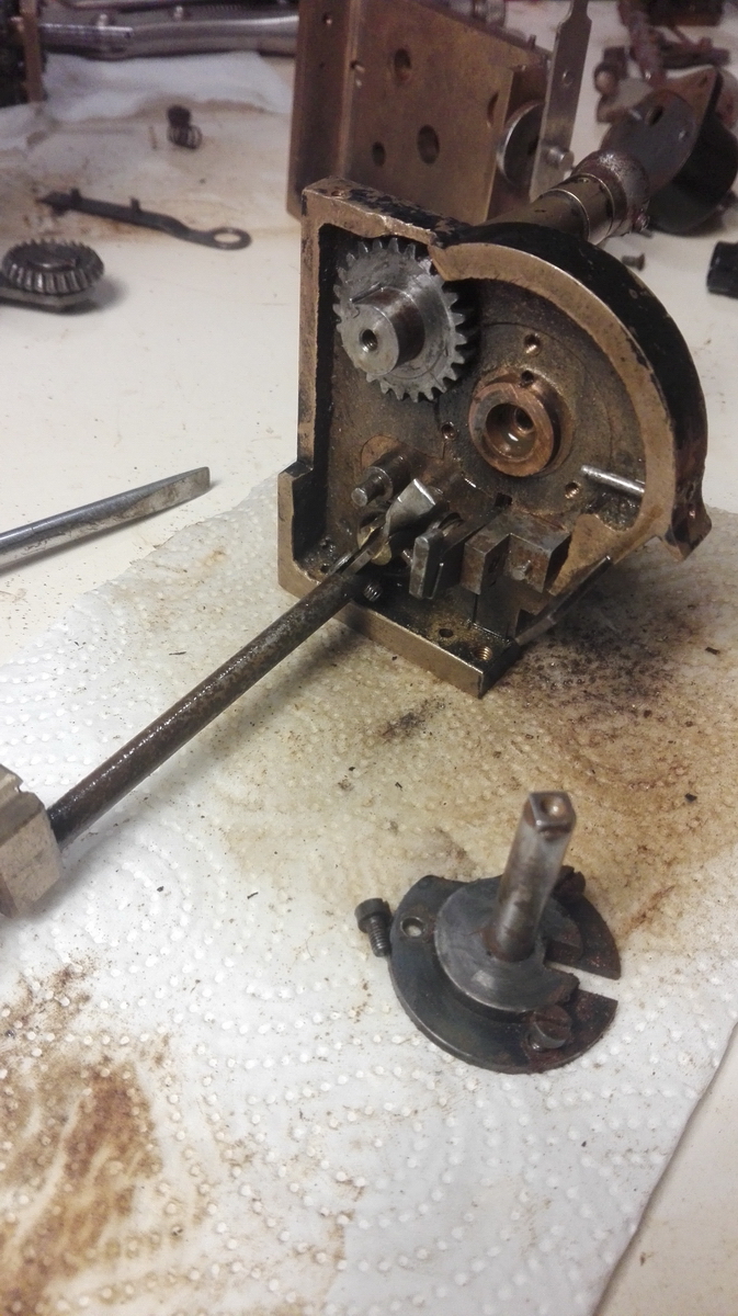
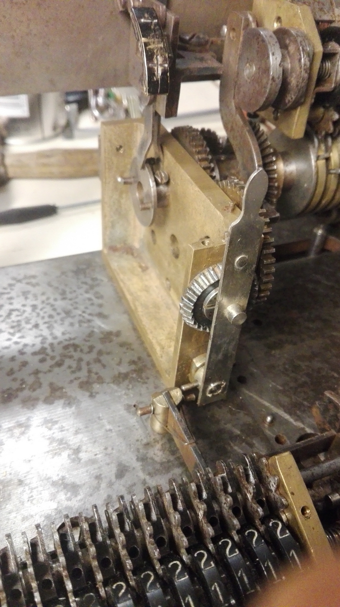
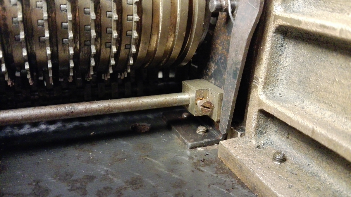
Since the tens' carry pins were caught up in the counter gears, the tens' carry cylinder couldn't be slid out - for this the counter needs to be removed. It is located by three screws and two pins.
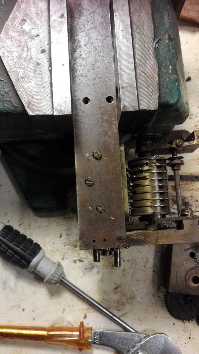
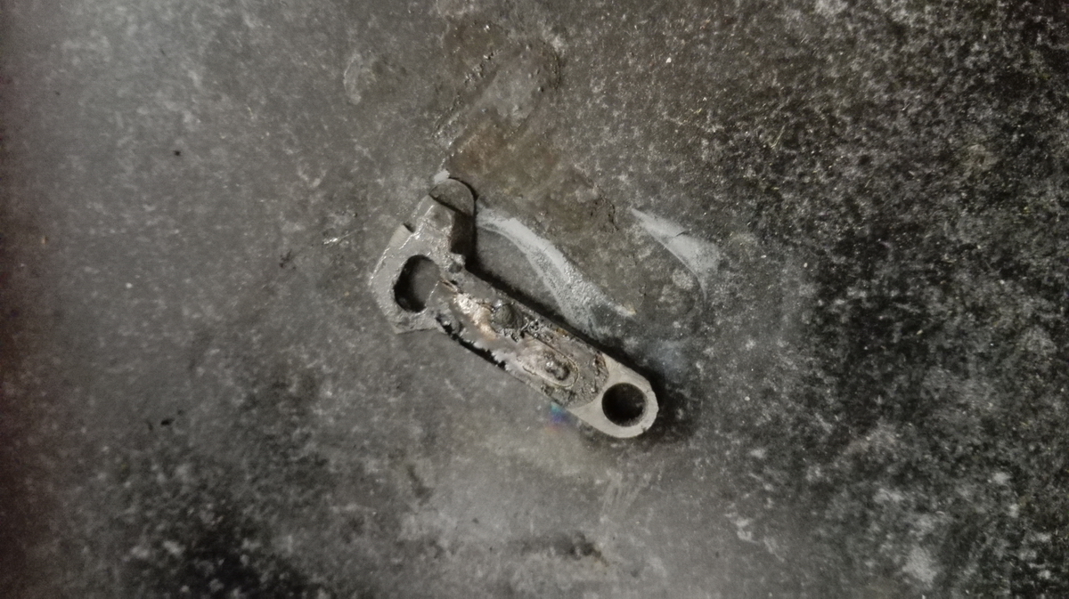
The screws are cheesehead screws, and contrary to all the other screws in the machine, which even in the state they were in did not cause too much trouble, it seems that these screwheads are actually made of cheese. You could feel the heads starting to deform when trying to break them free. They were a bit like the three little piggies - one came out without too much trouble - the second one needed lots more soaking in penetrating oil, a few smacks with a hammer and then I had to tighten it a bit further in order to then loosen it. For the last screw (the middle one, look at the state of it ...) I had to use every trick in the book to get it free. All of the above, but this time I also started deforming the screw head in the tightening direction. This is the time to get out the pin punch and hammer, and break it free by hammering at an angle on the side of the screw slot. At this point you have given up hope to be able to reuse the screw, because you destroy the slot entirely, but it did come free on the ultimate attempt. The next step, if you've utterly destroyed the head and it still didn't move, is to just drill it out, until the head lets go. If you're lucky, there would be part of the thread sticking out of the counter, which you can then grab with pliers and unscrew - if the tension is off the threads, they usually unscrew quite easily. Once the counter was off, I could rotate it so I could reach the cotter pin to tap it out (thankfully mostly very easy with Britannics!) and the counter could be bodily removed from the machine frame.
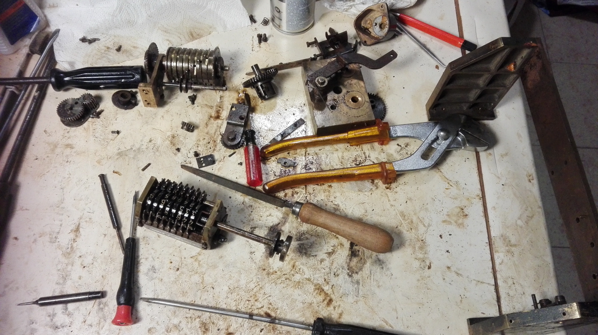
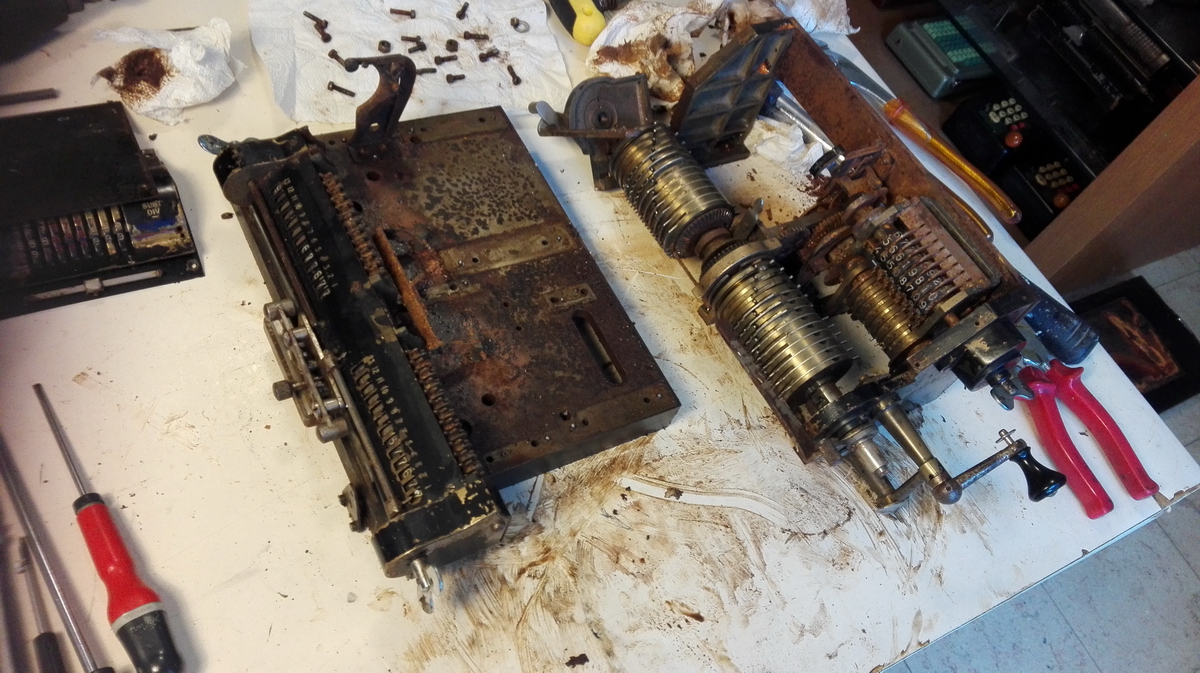
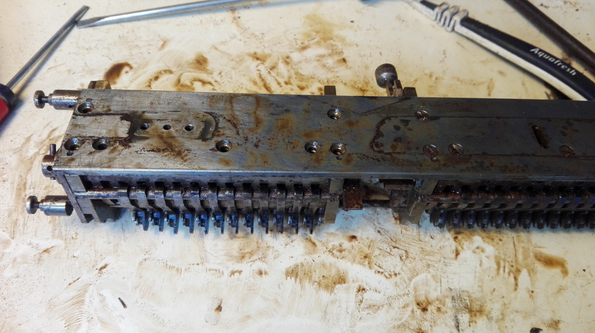
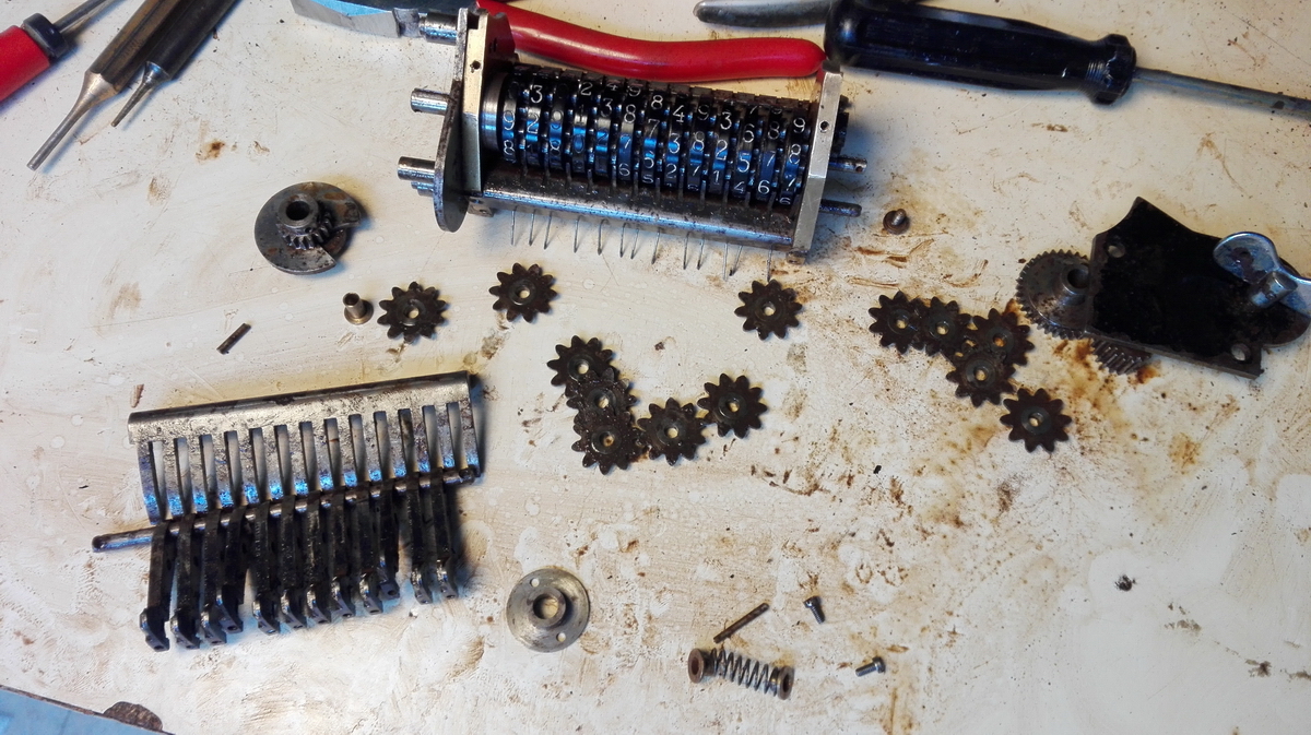
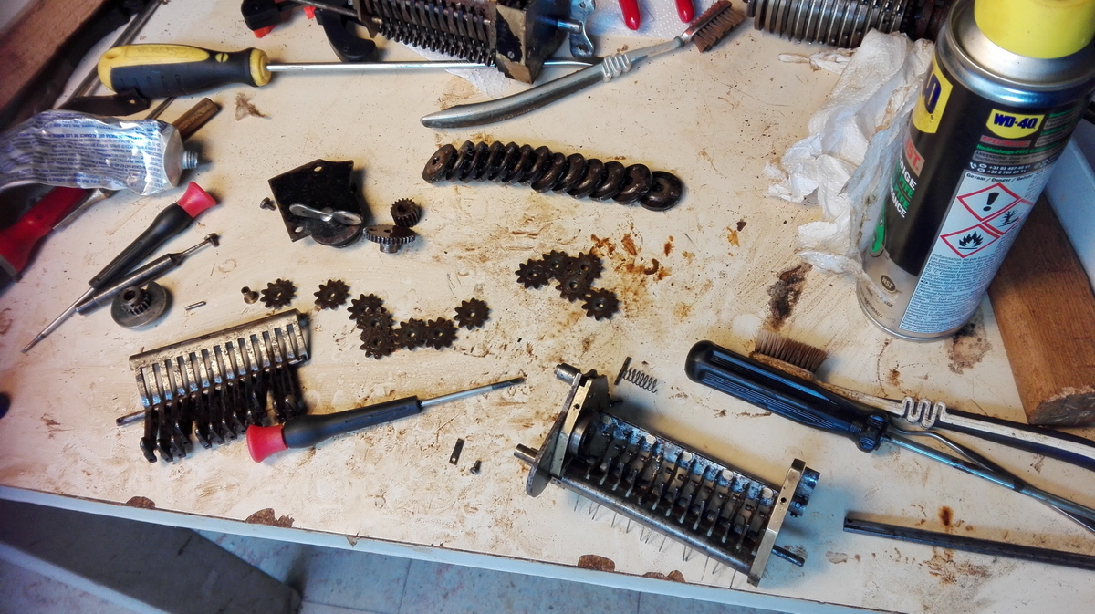
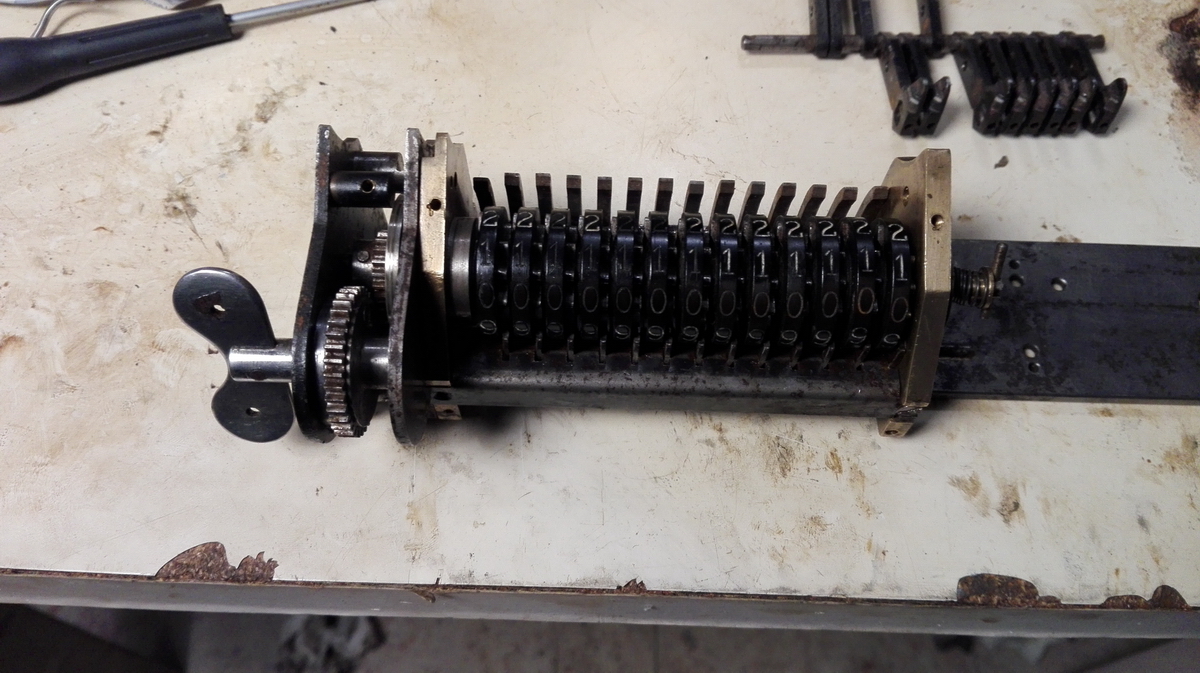
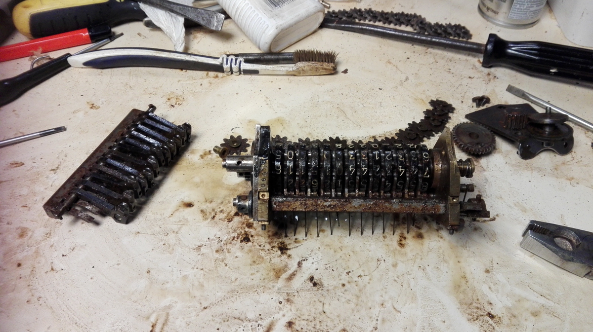
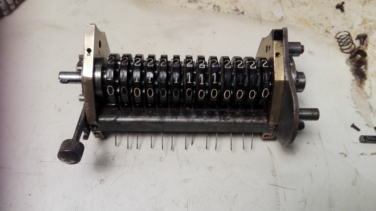
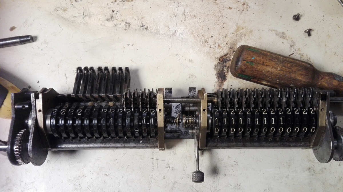
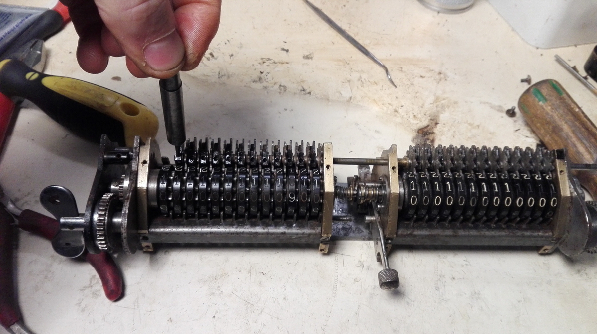
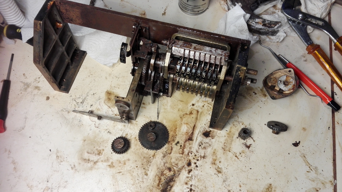
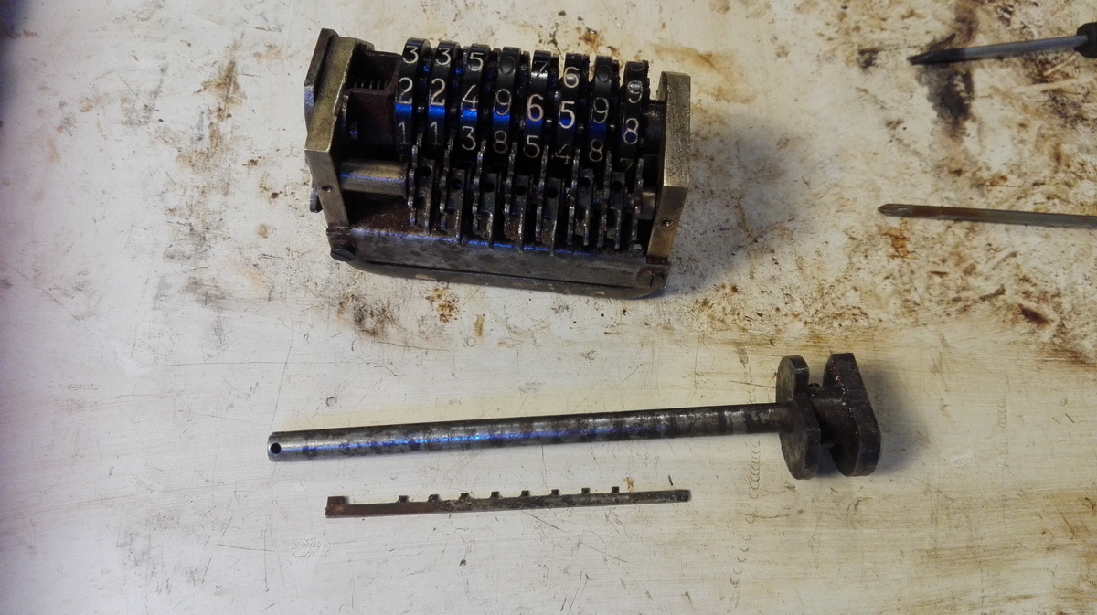
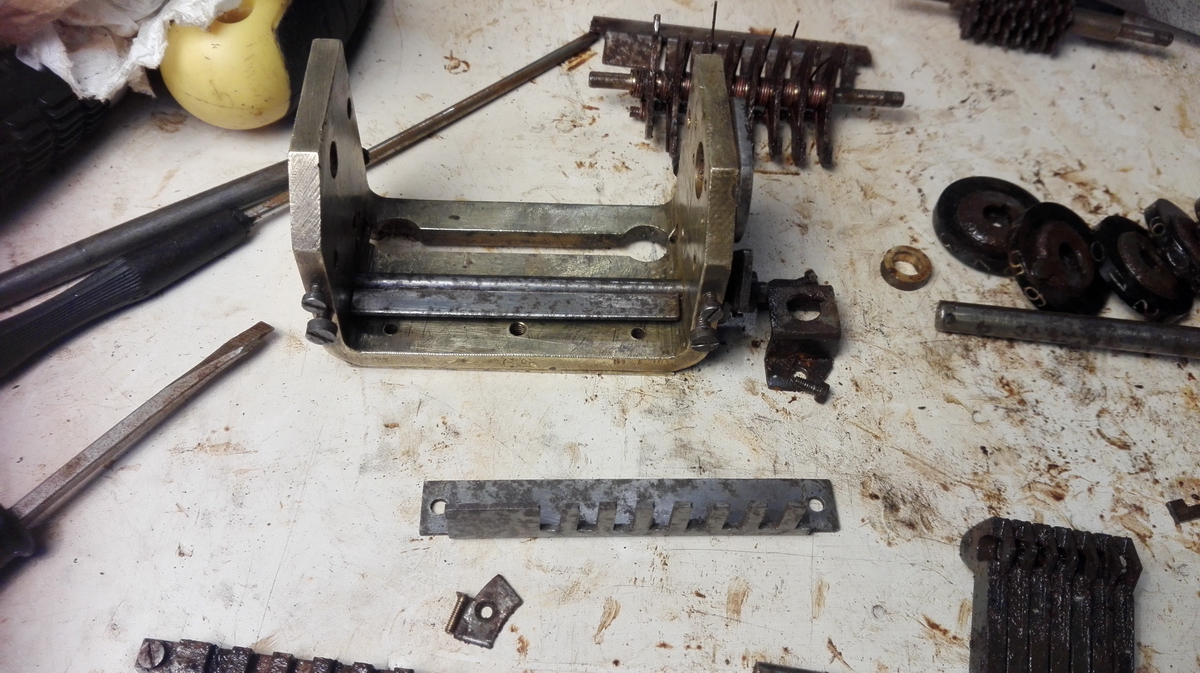
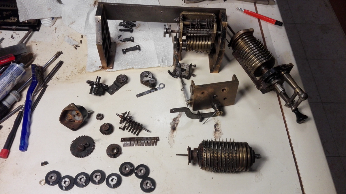
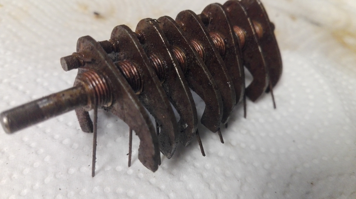
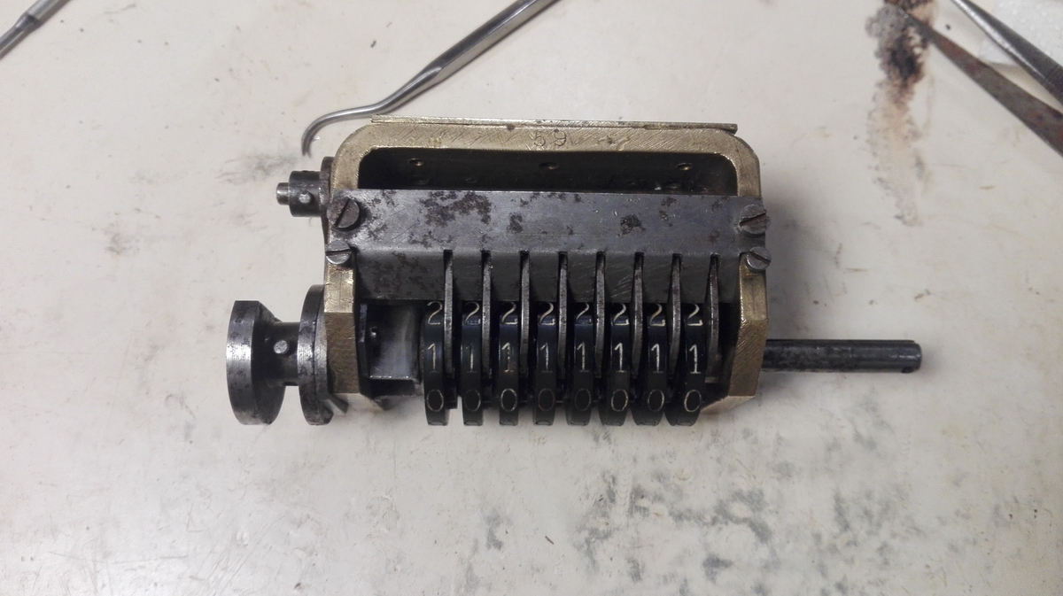
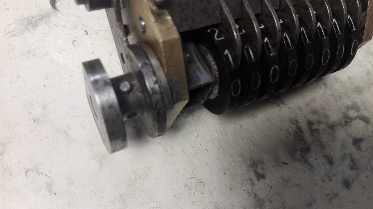
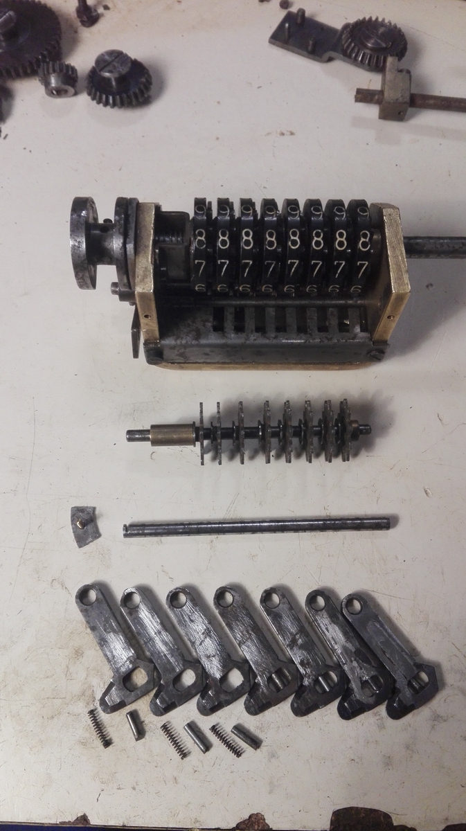
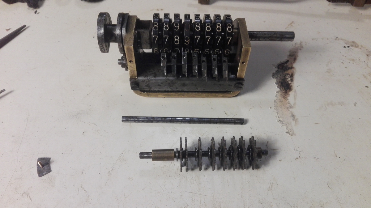
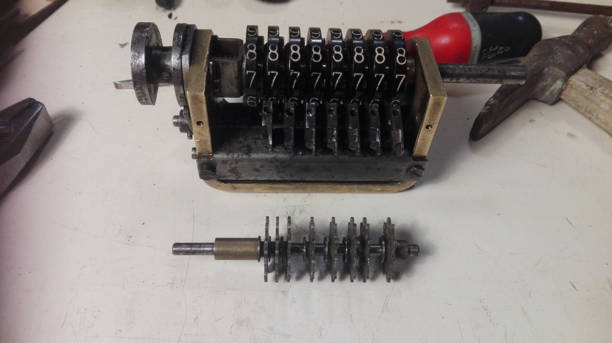
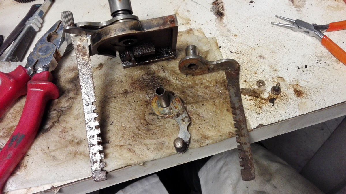
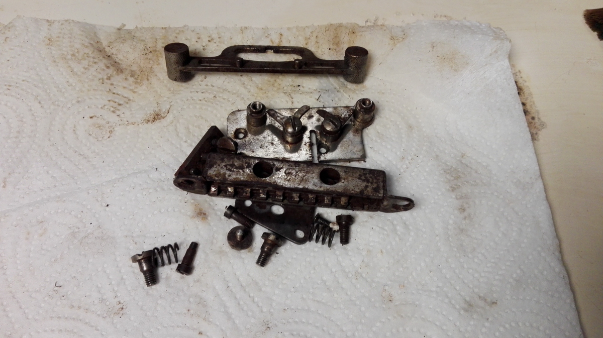
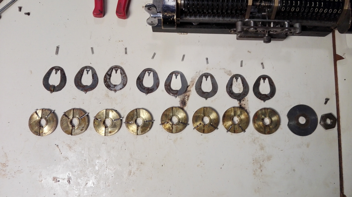
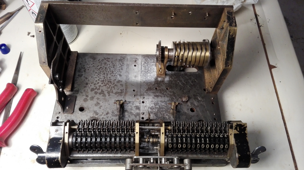
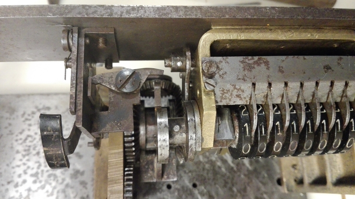
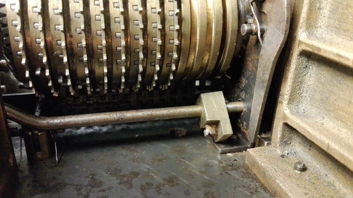
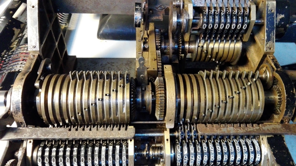
So this, then, was the state of the battlefield at the end of this stage. I had started tapping away with a punch at the counter wheels and intermediate gears, to get them free and break the bond of all the rust. Once they had all started to move at least slightly, I knew that I should now be able to slide the keyed shaft out of the assembly. But it was stuck. Very, very stuck. Getting it to move was a rather scary nightmare, involving about 30 whacks with a big hammer. If I hadn't been definitely sure that I would be unable to hurt the clearing mechanism in this way, I would never have dared to do this, but I was absolutely certain that it had to come out that way, and that I was doing the right thing - there were simply no other options. But with every smack with the hammer, I couldn't help thinking "why didn't it move ? It should move!" And then, after way, way too long, it did finally, thankfully, move. Phew. I called it a day at this point.
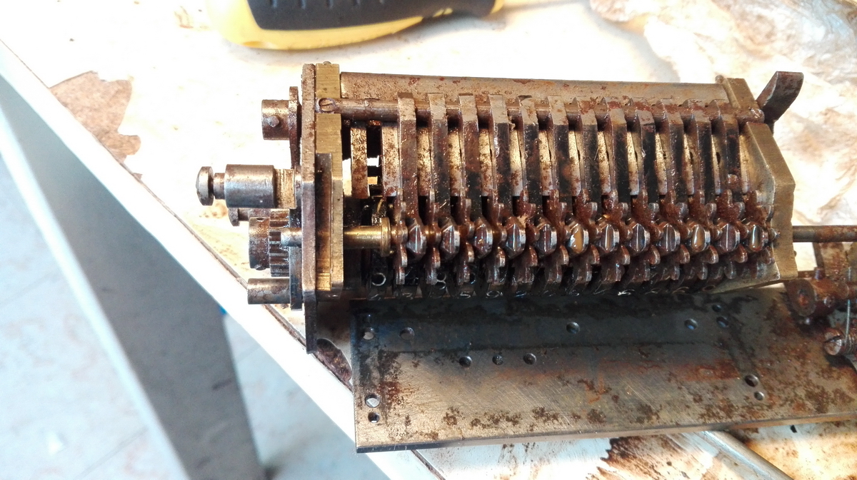
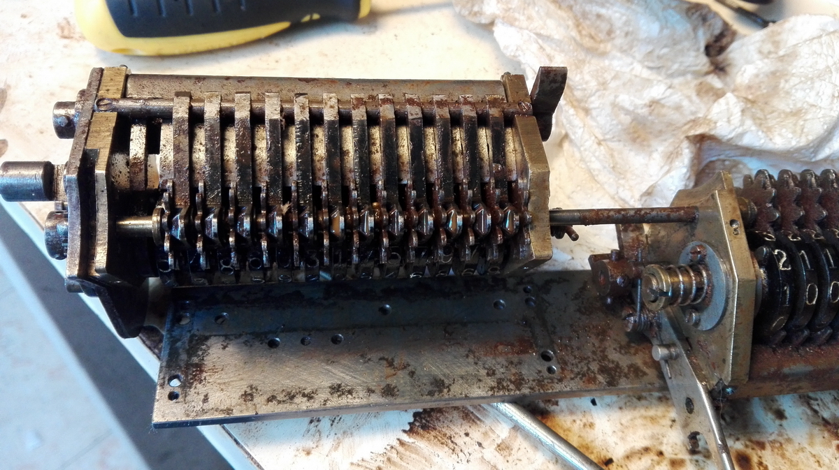
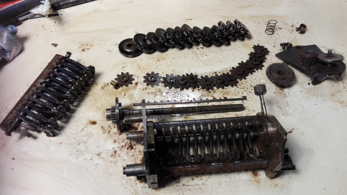
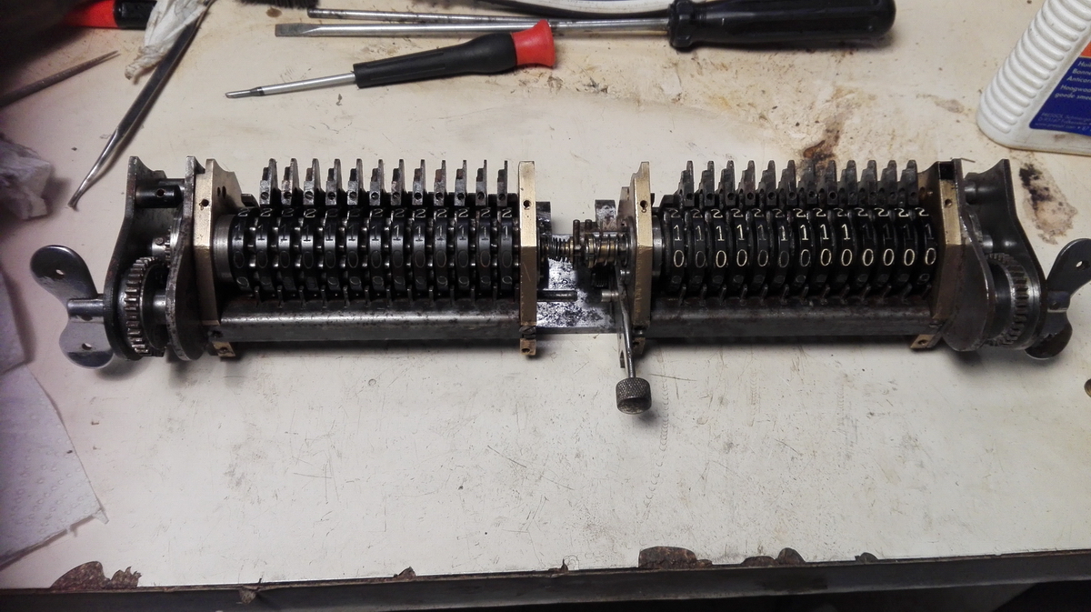
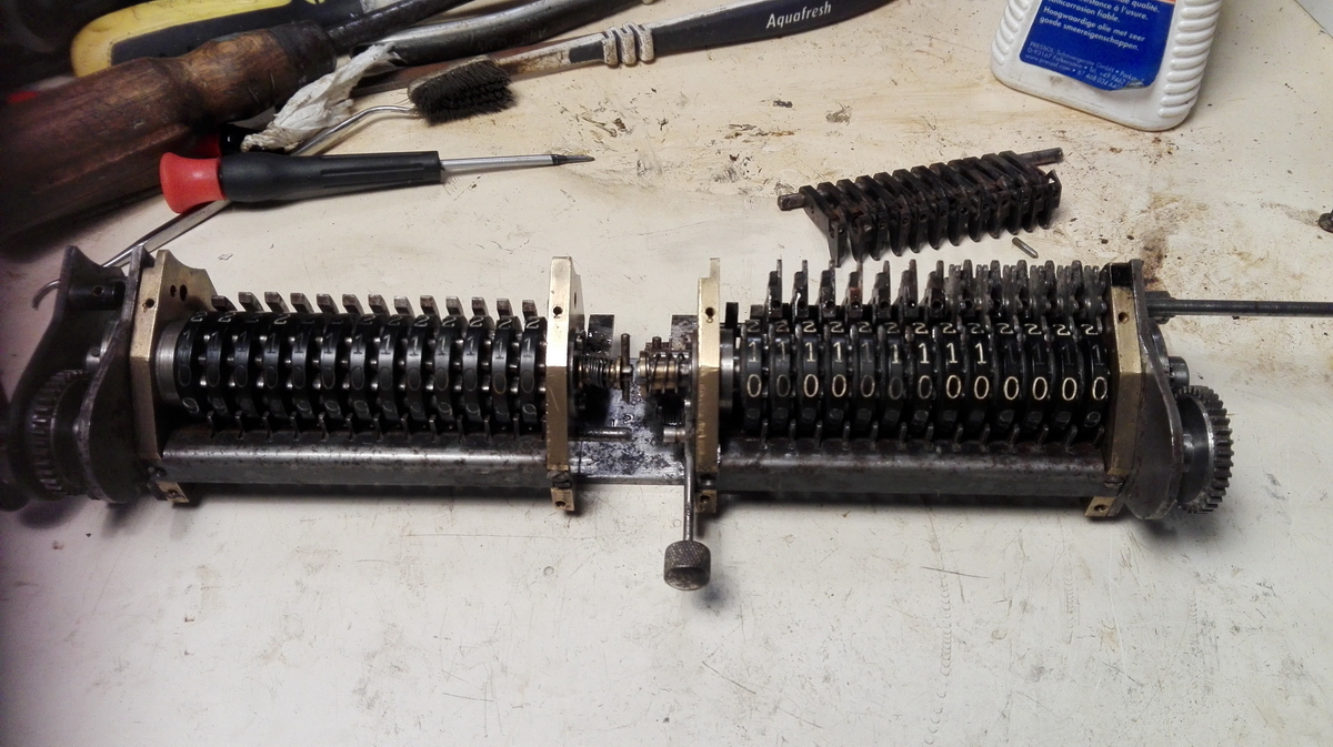
The next day involved further disassembly of the counter.
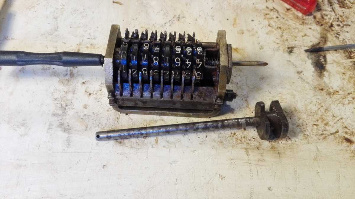
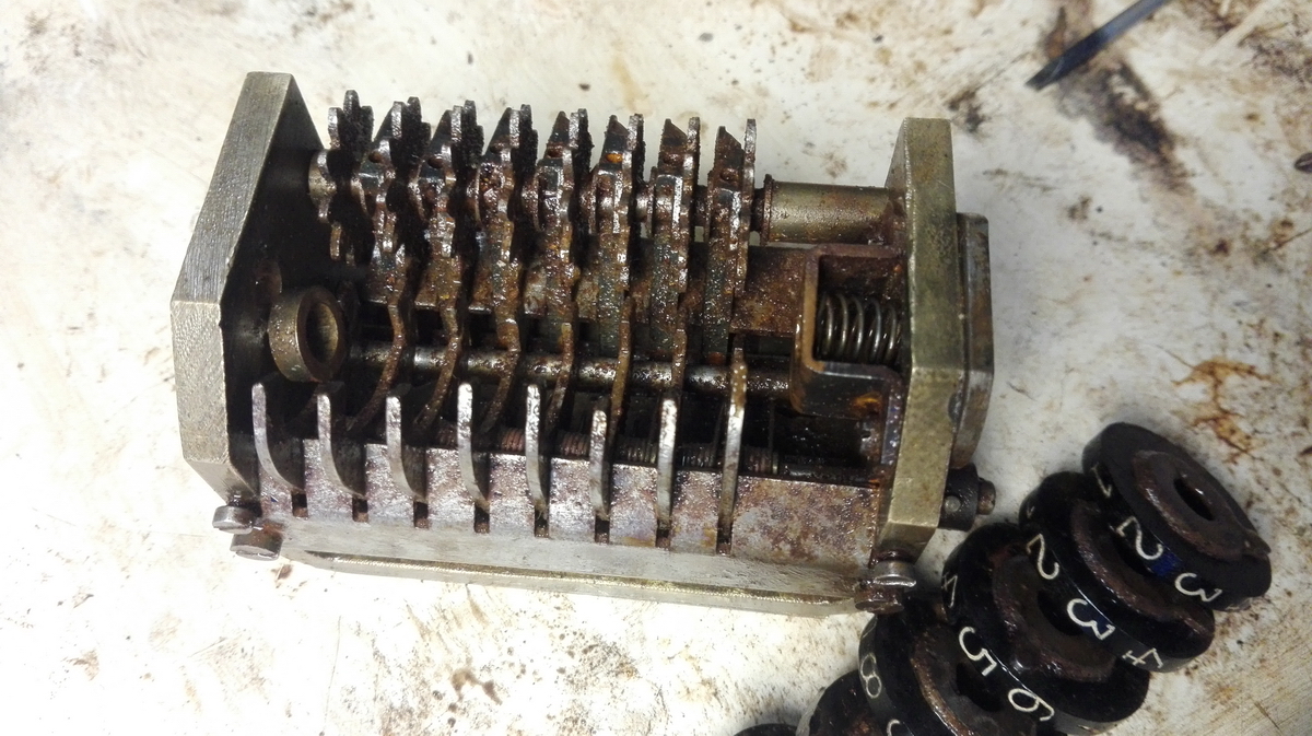
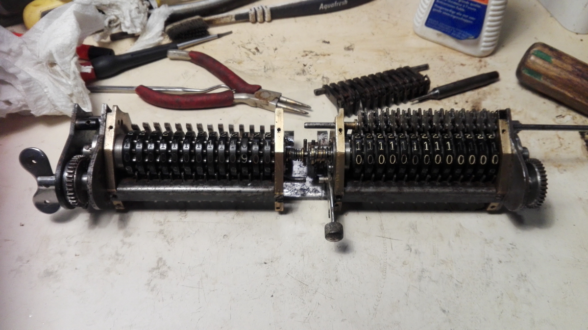
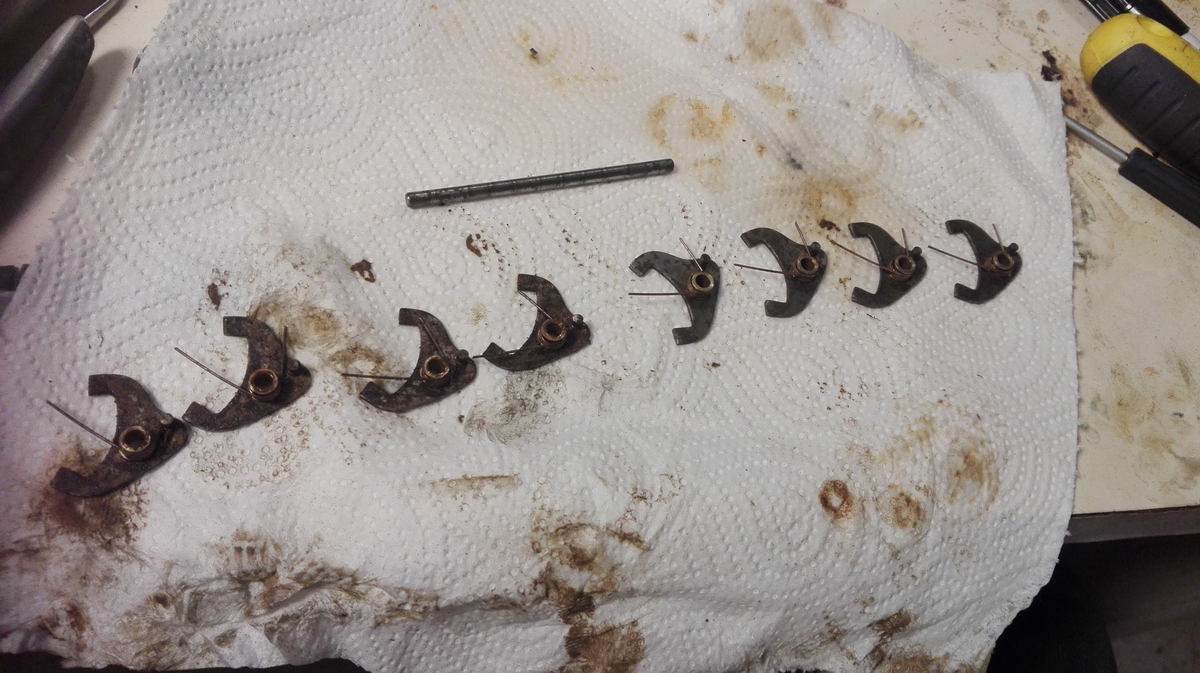
This was relatively uneventful, until I reached the tens' carry arms.
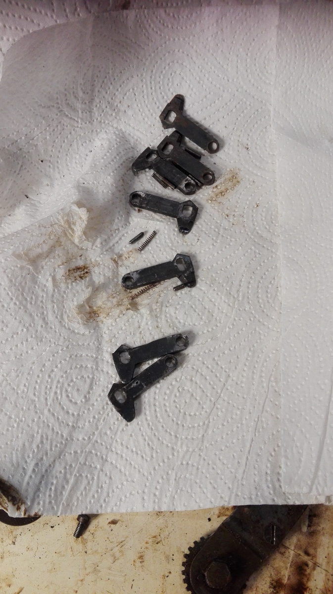
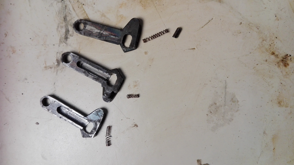
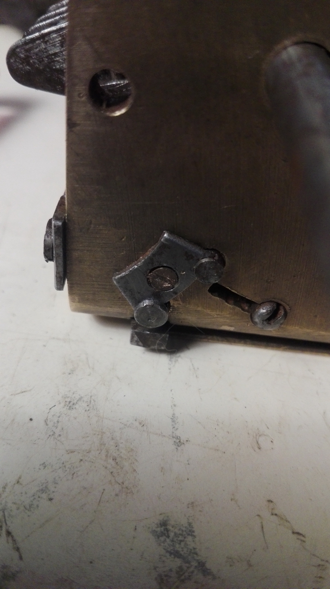
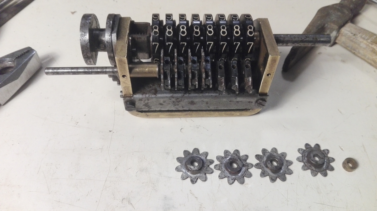
A tens' carry arm is a bistable mechanism, kept in its current position on the axle by a hardened pin that has one end ground into a shallow edge. This pin falls into a hole in the body of the lever, with a spring to make it exert some pressure on the axle that the arm is sitting around - when the lever is pushed in or out, the pointed pin is pressed down into the body by the axle switching position, and then pops back up when the axle has reached its other location in the oblong cutout in the arm. It was a small wonder that I didn't get into this kind of trouble with the other two registers, but since the only thing trying to push the pin out is a relatively weak spring, when they get stuck through rust, there isn't much that can be done. A trick that sometimes works is to soak them for a long time in penetrating oil, and then push them in and twist (with a special tool formed to fit over the pointy edge of the pin). With a bit of luck, with the bond broken, they can then be coaxed out. But sometimes not. If even longer soaking and several stays in the ultrasonic bath in a up of penetrating oil won't help, then the only recourse is to drill them out. Four of pins in the carry levers came free at various stages of this exercise, and I was able to drill out one, but I destroyed the other two (a hardened pointy steel pin isn't exactly the best starting position to start drilling if you have any choice ...). So now I will need a parts machine to steal two carry levers from. Luckily they're all identical in Britannics - at least in the 1A and 1B models, the 2B is different!
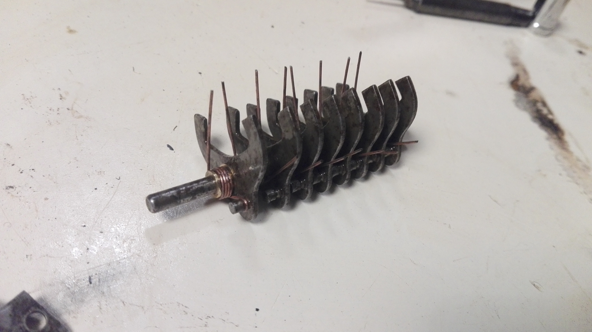
While the tens' carry arms were fizzing away in the ultrasonic bath, I cleaned up the counter frame.
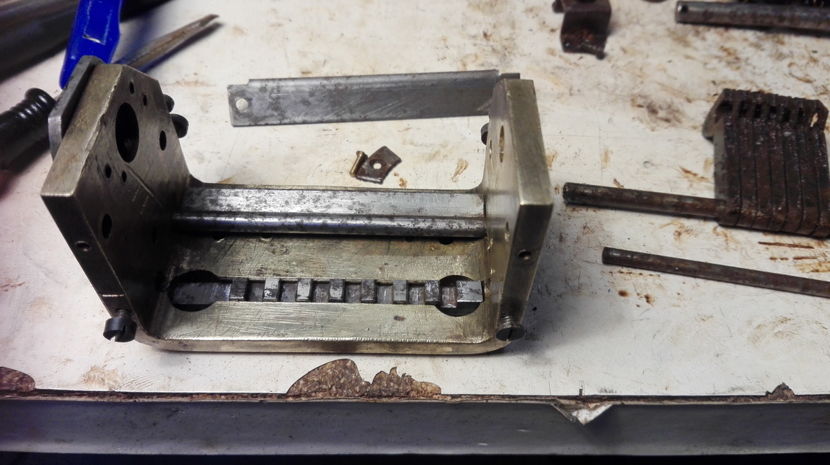
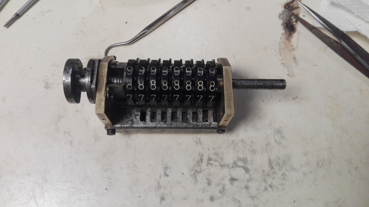
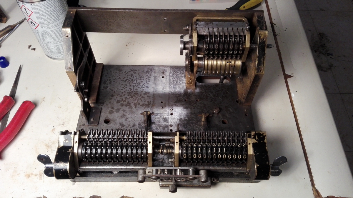
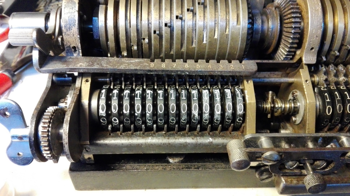
As I continued cleaning, I built it back up until I could see if the clearing would work reliably - and luckily it did. Also the tens' carry drum was cleaned up.
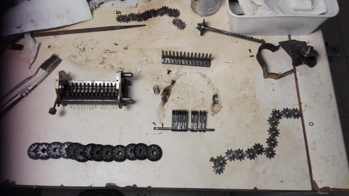
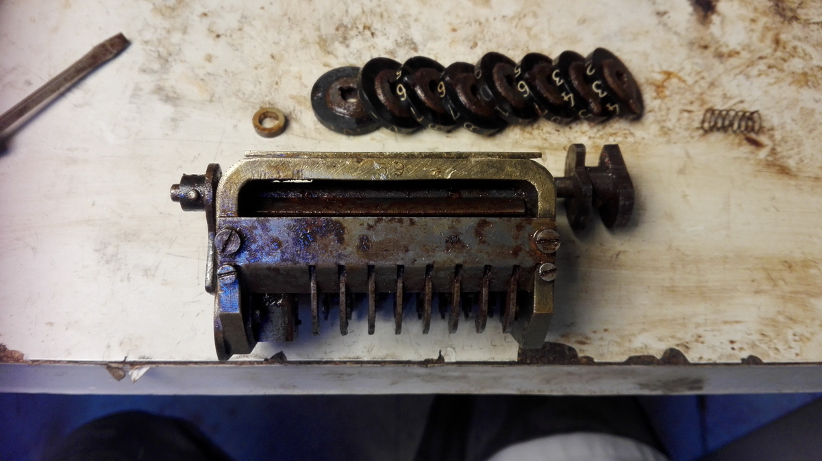
Finally, he side frames and rear steel plate were cleaned, and everything that was cleaned was provisionally assembled, awaiting the cleaning of the counter wheels and their locking levers.
There were plenty more loose parts to clean and reassemble - for starters the direction change mechanism for the counter - it already received a good scrubbing in this first picture!
That's (even) better
Also some of the intermediate gears
...and the the indicator mechanism for +/- and its support.
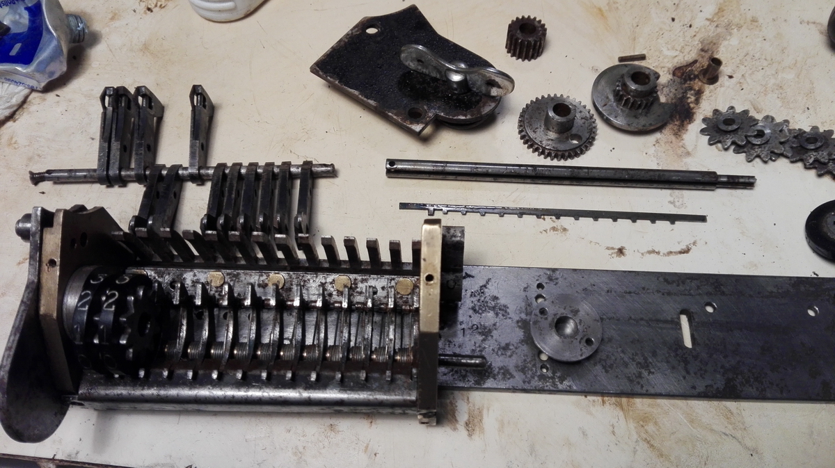
Finally, the main upright in the middle of the machine:
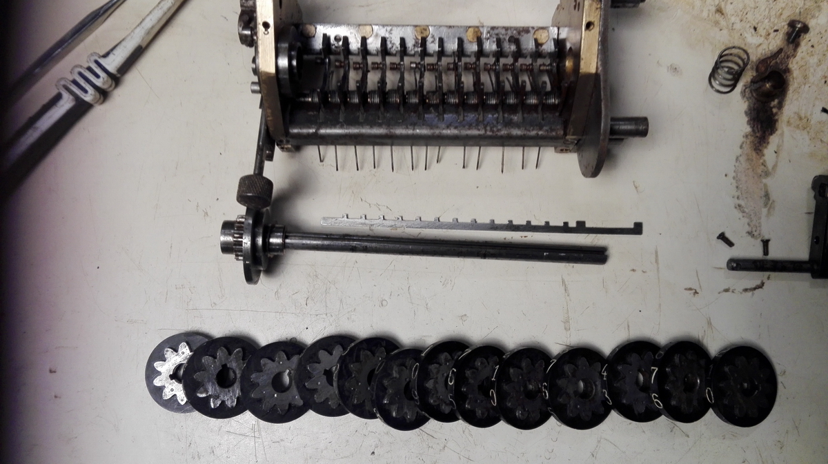
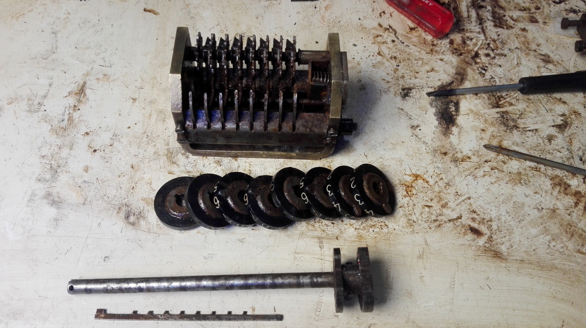
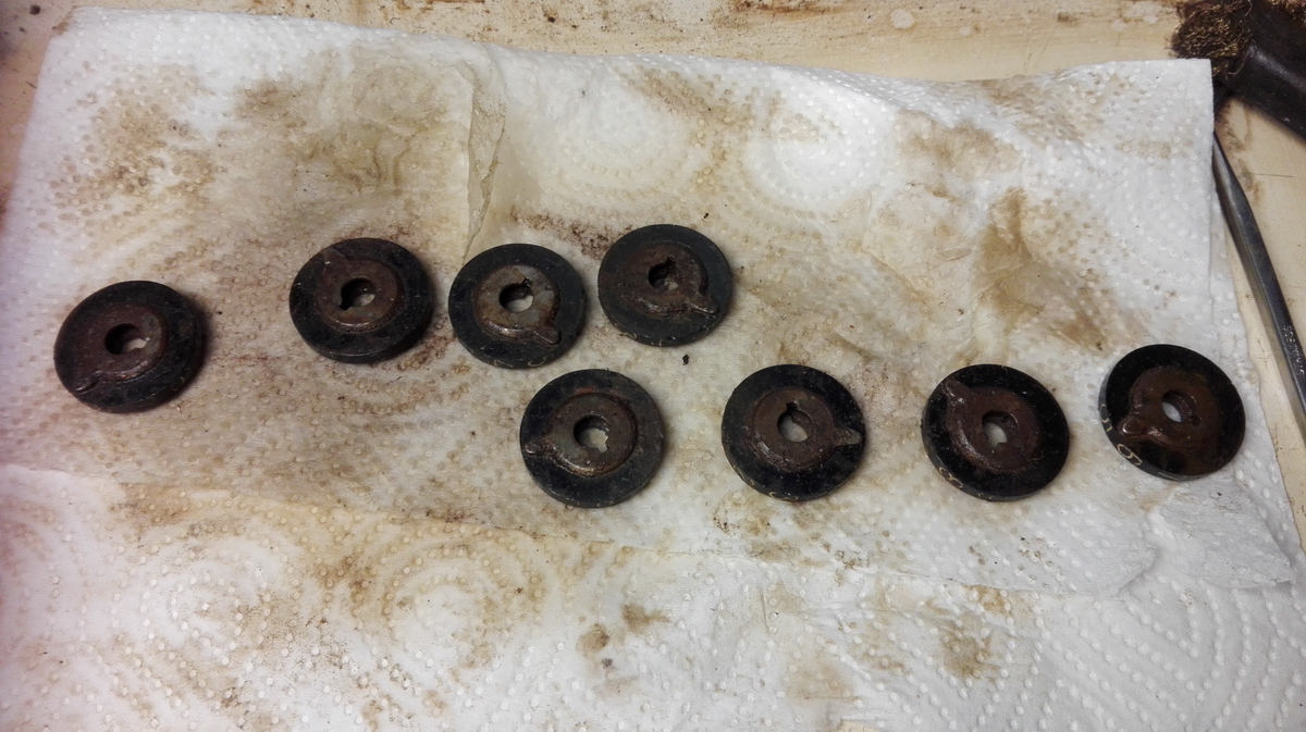
and the numeral wheels in their "as found" condition
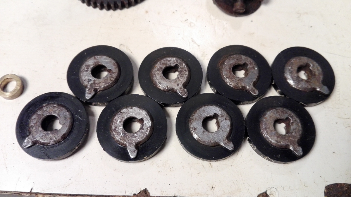
These are the numeral wheels after cleaning - they are engraved on the side with their position in the machine.
This was the state of the table after another two hours of cleaning - the cluster of dirty and rusty parts keeps getting smaller!
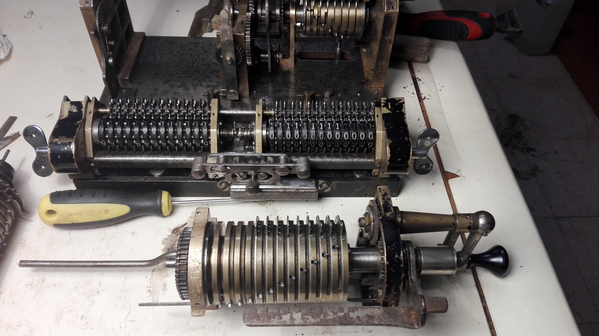
I then started cleaning up the pinwheel cylinders. This is the leftmost one - before:
during:
and after.
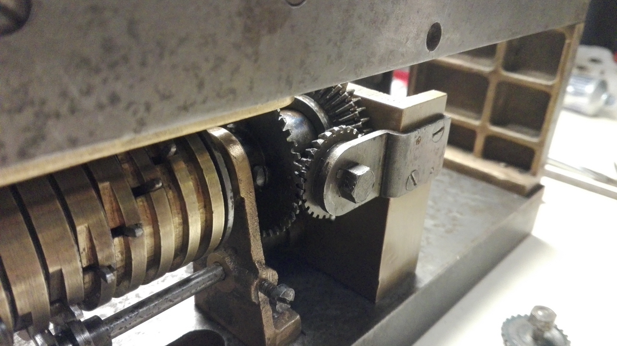
I subsequently found out that the clean steel part at the end should be able to shift from left to right, to engage the dog at the end with the slot in either pinwheel cylinder, making them turn in the same, or a different direction. Since this part was still rusted in place, it took a few taps with a hammer on a socket to get it to start moving.
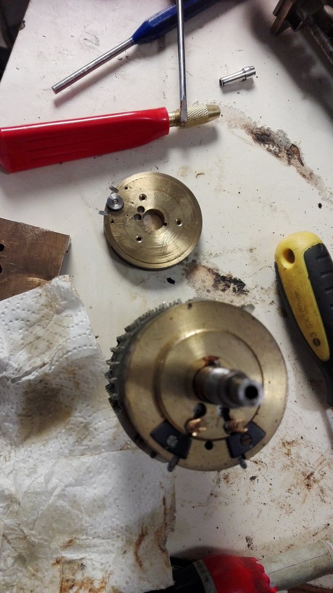
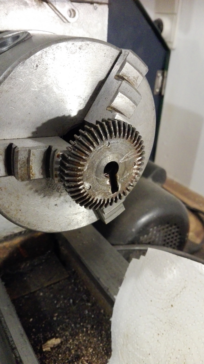
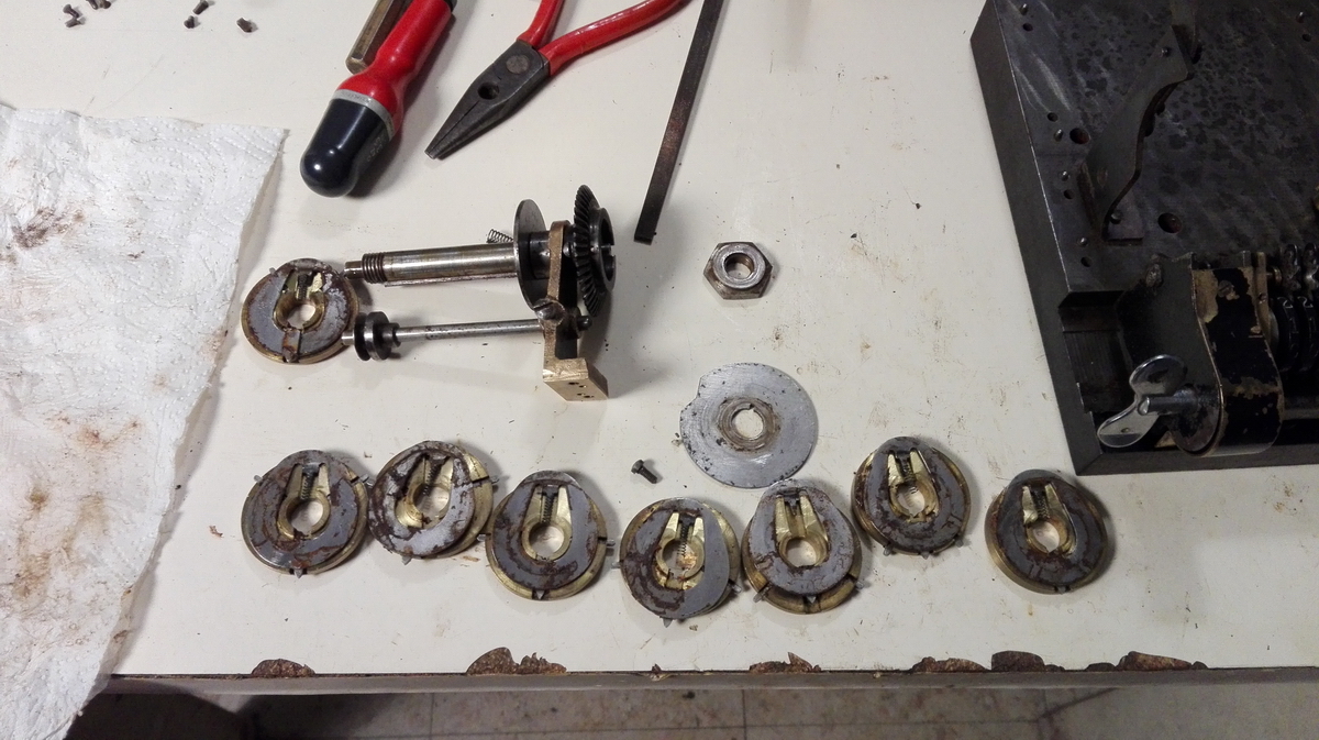
The righthand pinwheel cylinder also has one of these combinations of straight and conical gears, this time on the other end of the central upright. I concluded they were also stuck and needed freeing up. So I levered, tapped, and lubricated away, and could not get anything to budge. I then decided to take the entire assembly off. For this reason, I found the two locking screws on the collar that locate the gears on the axle. Finally, with the entire pinwheel cylinder held in the vise, and tapping in a counterclockwise direction, suddenly the gear started moving, but to my surprise, it unscrewed. And what I found then was even a larger surprise.
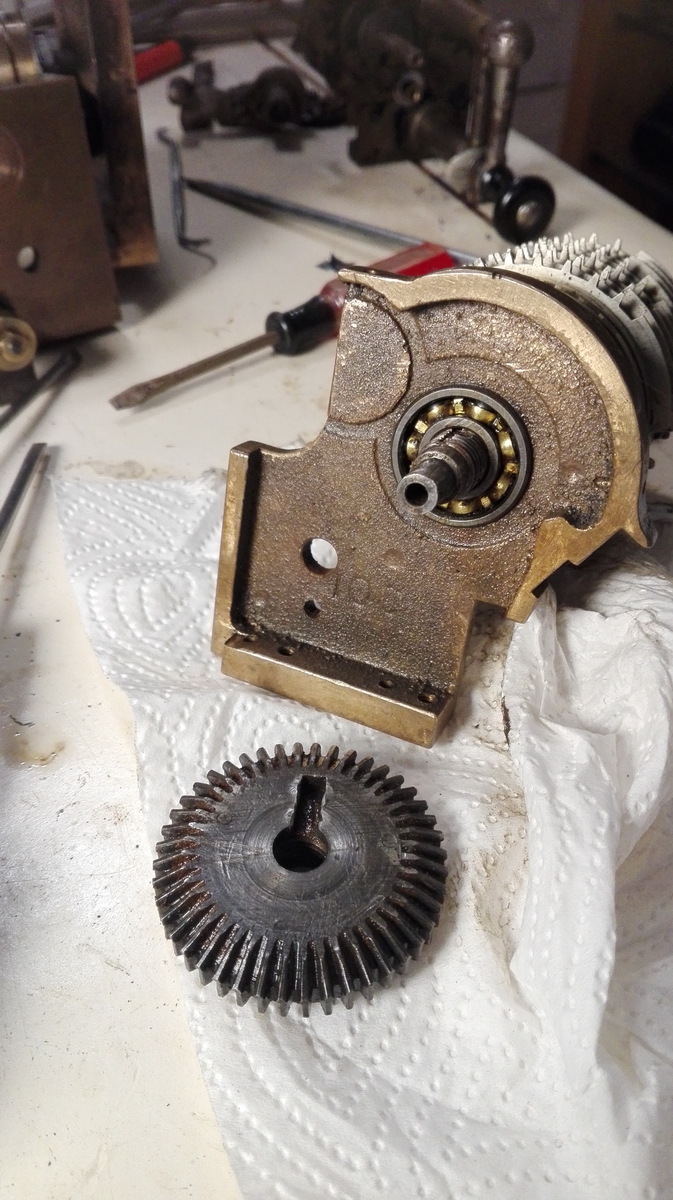
The upright has a caged ball bearing.

On closer inspection the bearing is actually part of the pinwheel cylinder - the gears that are screwed on press on the inner bearing shell, which in turn presses on the brass disks that make up the pinwheel cylinder. This means the pinwheel cylinder would now disassemble easily, but since I didn't want to go there at all, I left it well enough alone.
Then the set of conical and straight gear could be put in the lathe to finally pry them apart. I managed to do that by carefully inserting an exacto blade between the two gears, and tapping it in with a hammer.
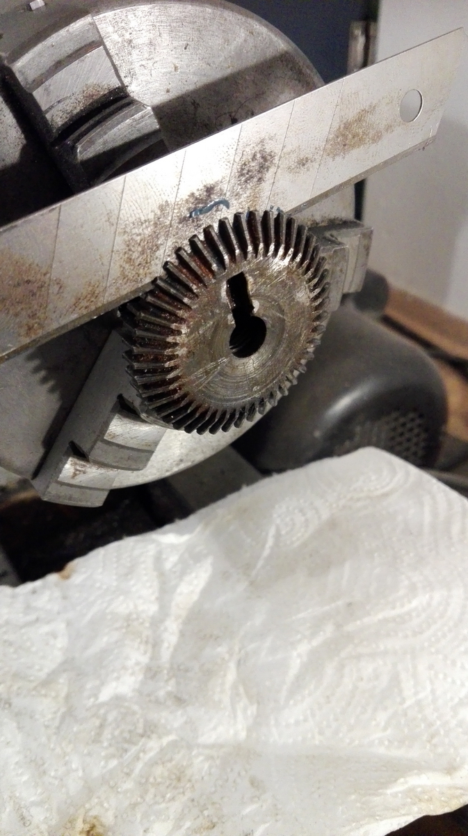
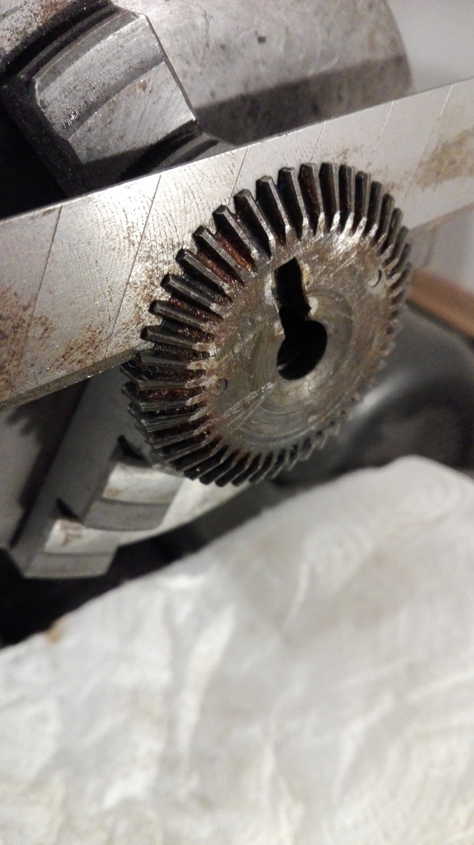
Widening the gap tapping the blade all around the perimeter, I discovered that the two gears are not at all supposed to rotate with respect to each other anyway - they are pinned together with three pins.
So I tapped them back together and cleaned them up, cleaned and lubricated the caged ball bearing, and put the whole thing back together.
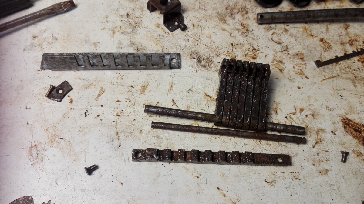
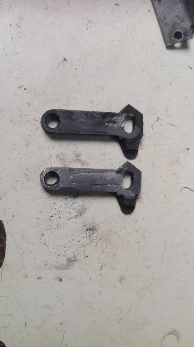
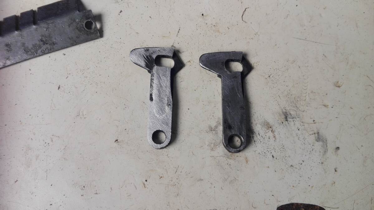
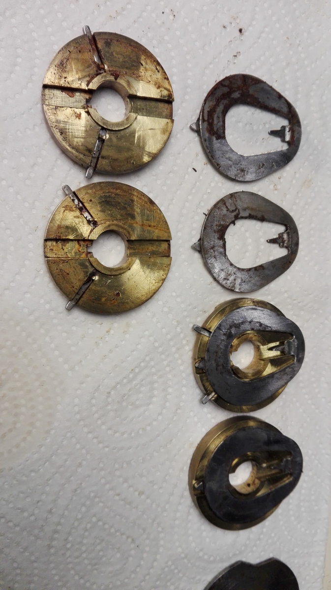
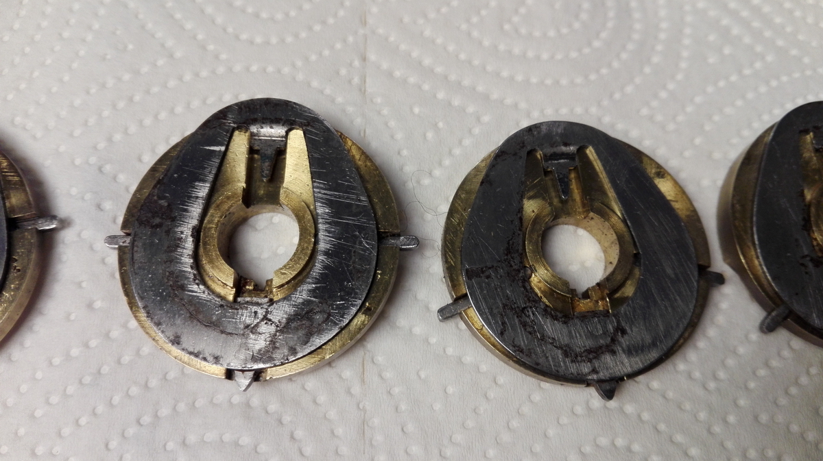
In the meantime, a different problem arose. Remember when I wrote that I had written off two of the tens carry levers, and that I would have to replace them with those from a parts machine, but that luckily all Britannic tens carry levers are equal ? The first machine I disassembled was my somewhat scruffy looking 2B - only to find the tens' carry levers to be completely different. Not to worry, moving on to the 1A. I duly disassembled two of the tens carry levers from the carriage, and then I found this:
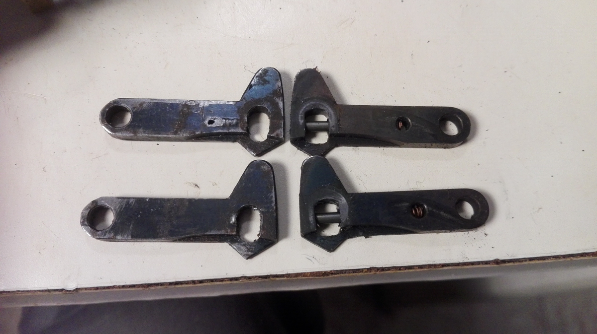
Destroyed levers are on the left, the ones from the result register of the 1A are on the right. It turns out the ten carry levers in the Britannic Duo counter register are of the opposite hand to those in the carriage, and probably pretty much unique. So that necessitated putting plan B in action - milling out a slot in the levers to press in a steel replacement part to be drilled for the sprung pin. Since I don't have a milling machine at home, I used the enormous vertical mill in the university workshop. It takes giant Clarkson chucks, and has handwheels 20 cm across, about a metre away from where the milling is happening, somewhere deep in a giant vise. So in fact, there is no hope whatsoever that you can see at all what you're doing. I still managed to get the slots about equally wide (one is 3mm, the other 3.4mm) but they are not equally deep at either end, so it will take some filing to make a piece of steel that fits so that I can solder it in. I did manage to save one-and-a-half spring, so i think that will be sufficient for it to work.
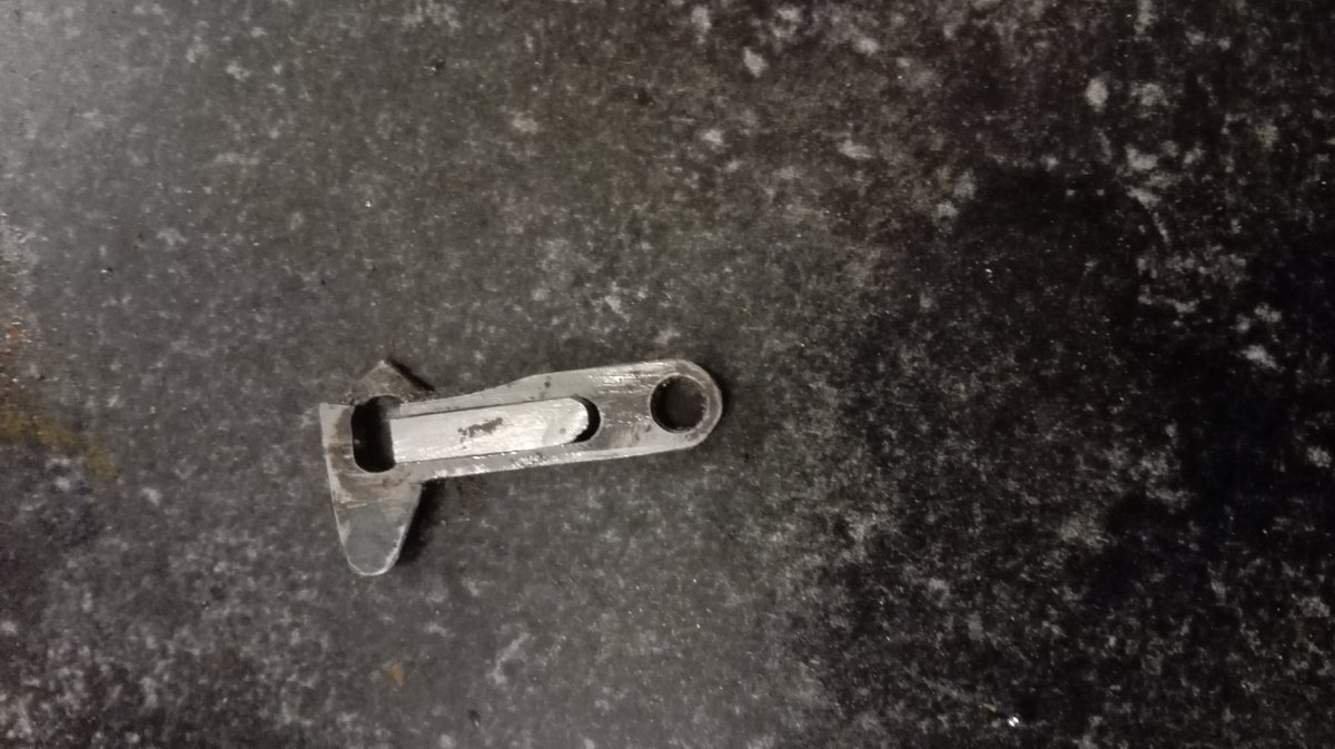
With fresh courage, I started shaping the piece of steel I needed from a 6mm nail.
After cutting it of, you have this:
Then we put it in, file it flat, and solder it in place.
We do the same with the other lever:
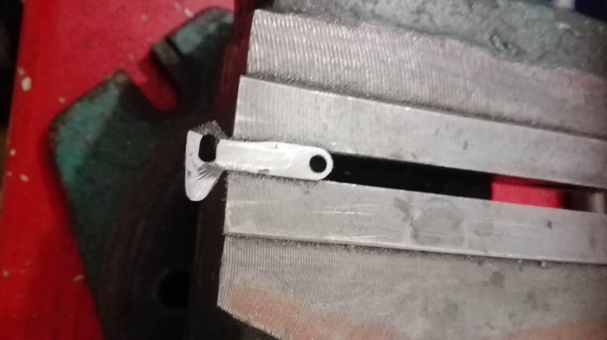
And this is what they look like when finished:
Next up: re-drilling the holes for the pins. I did one in the lathe, but that was not a great success, and the other in the drill press.
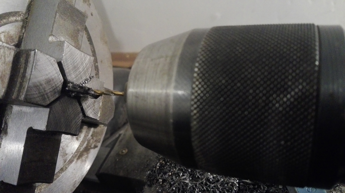
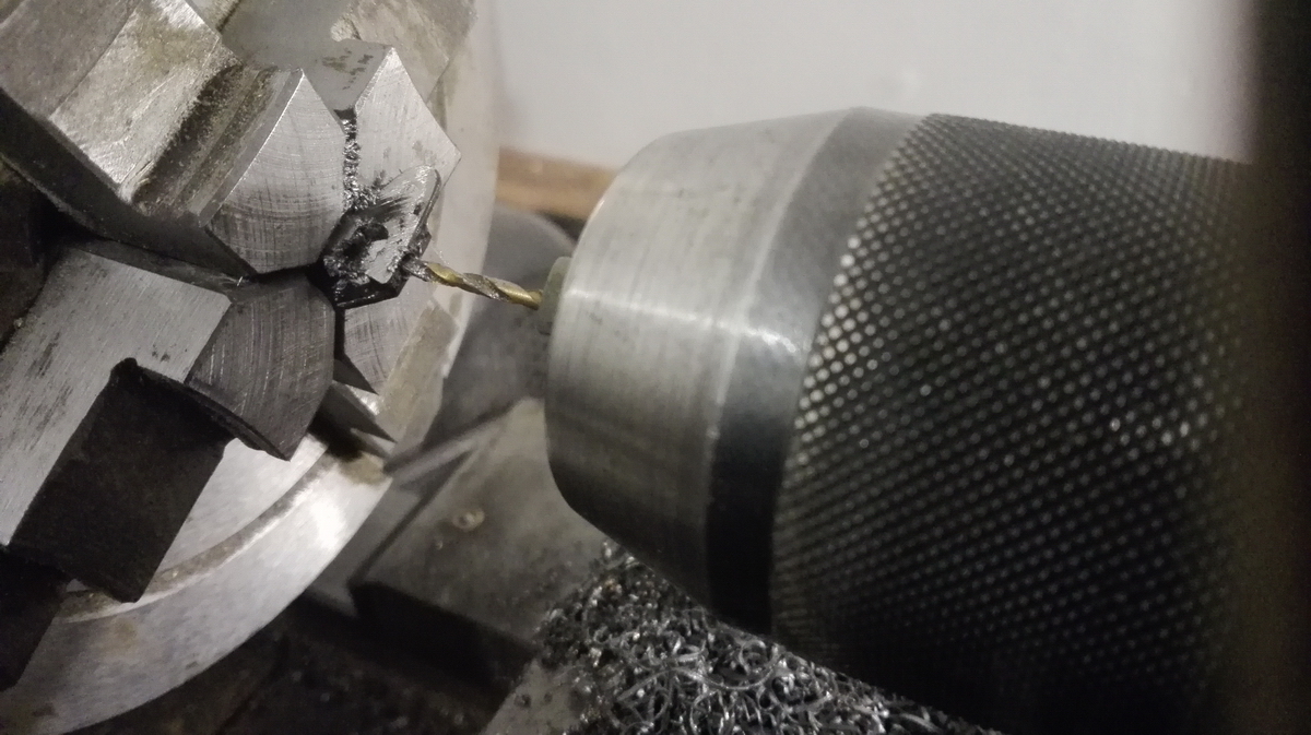
If you don't have a proper fixture, and a very rigid machine, this operation is almost guaranteed to go wrong, because the damn things are so narrow - something like 2.5mm, while the hole needs to be 2mm. It is nearly impossible to keep the drill straight and pointing in the right direction. So I wasn't able to drill as deep as I'd liked, and I damaged the sides, but I could compensate by making the pins slightly shorter, and nevertheless was able to save these parts.
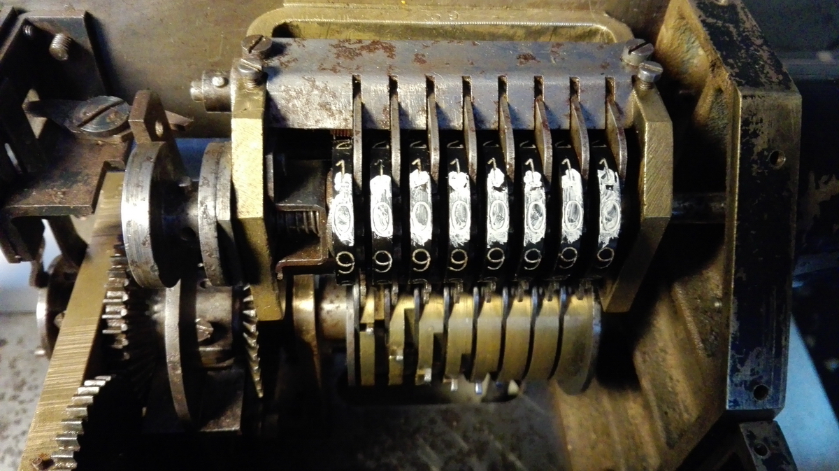
When I was confident that things would be all right with these levers, I could move on with the locking arms for the counter register. Here they are, fresh out of the machine:
Disassembled:
And cleaned up and back together:
Then reassembled into the counter register:
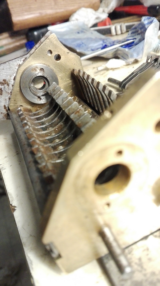
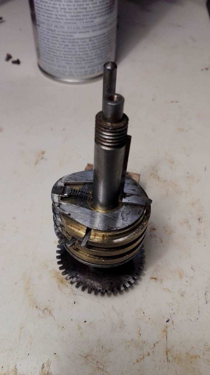
Getting this spring right took some doing ... it needs to grab behind the tab on the key in order to push it to the left, but the steel collar just to the left of the brass frame is one of the few parts that I was totally unable to take off, and I didn't want to drill out the screws. It did take me over an hour to get the shaft back into the register - because all the counter wheels need to be in place, the key needs to be in place, and then somehow you need to compress the spring and hold the key in such a way that the shaft can be inserted and the spring nevertheless hooks behind the tab on the key. I can tell you, it is nearly impossible. At one point I thought - screw it, I'm driling out the screws ... but then I had a few attempts in which I came tantalizingly close to success, and that encouraged me to keep trying - finally to be succesful. But that was the last thing I did for the day!
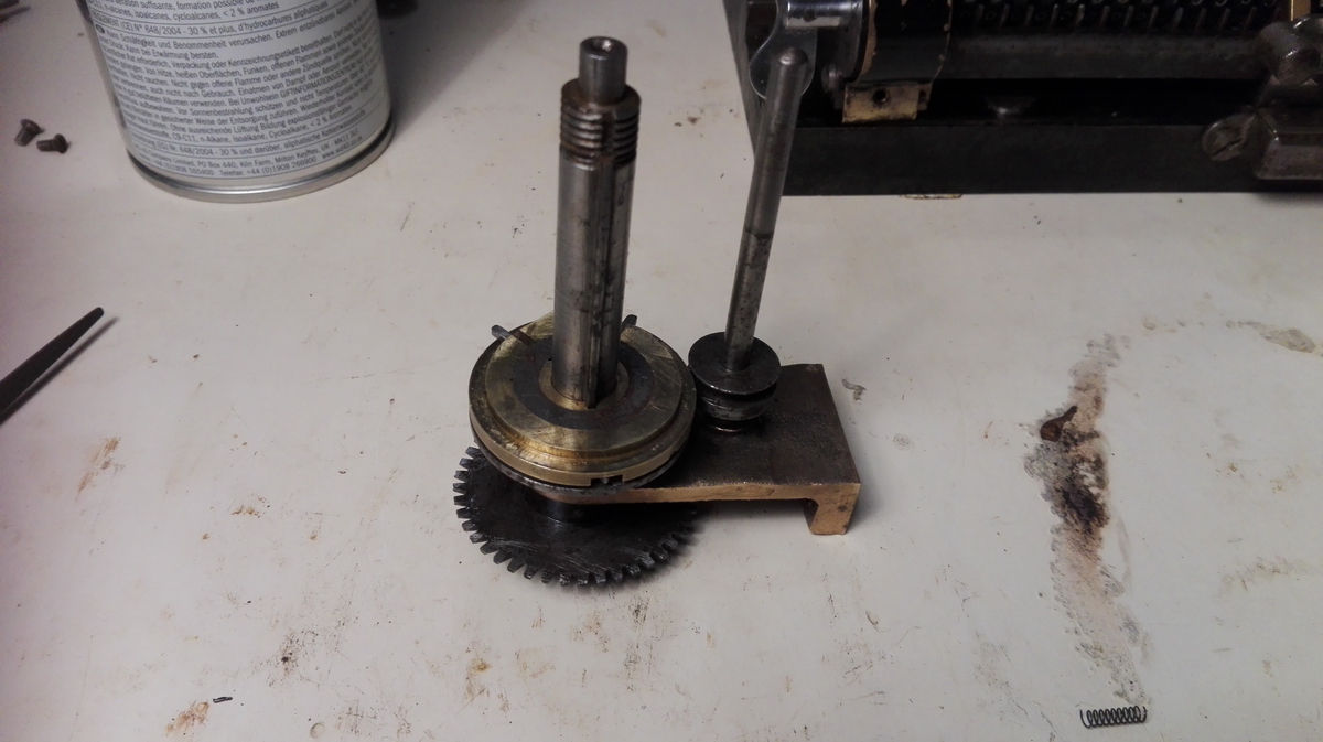
I then mounted the register back onto the frame to see what everything would look like, and to test whether it would clear properly. It did.
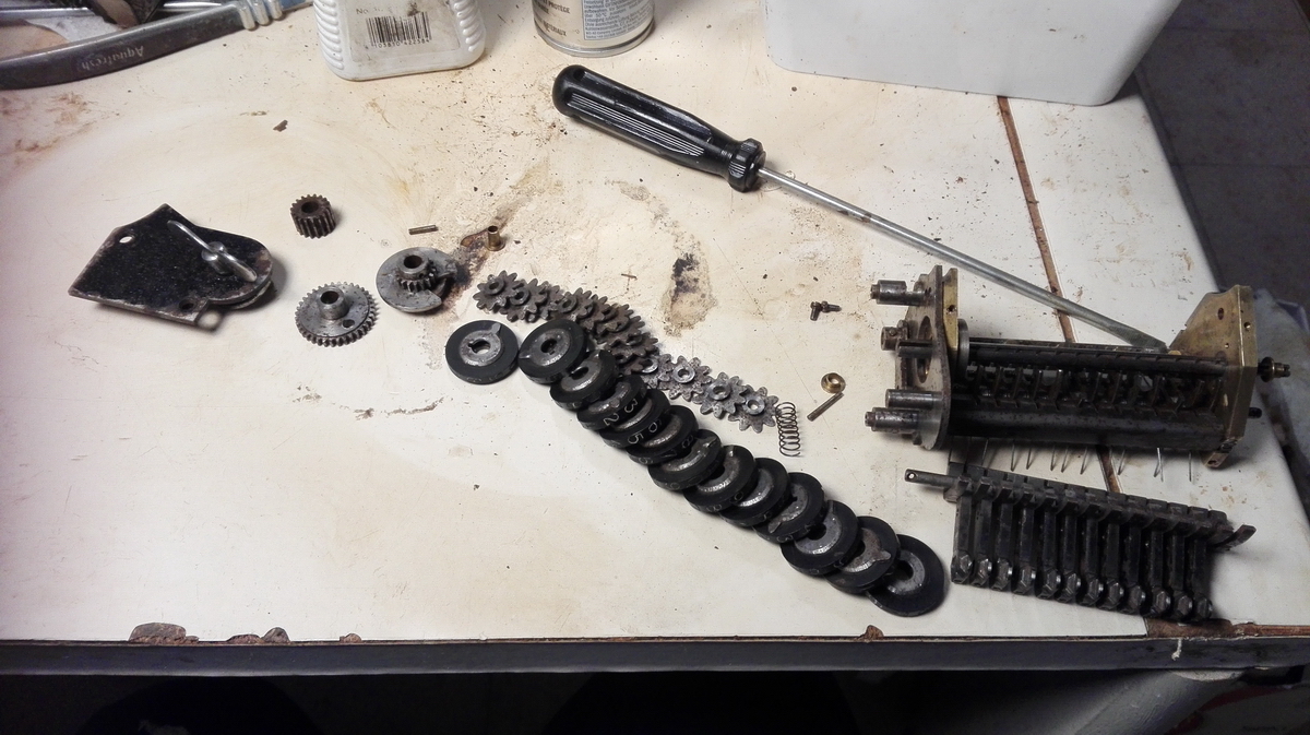
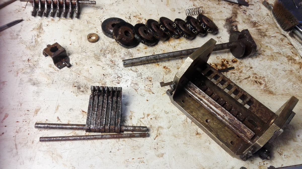
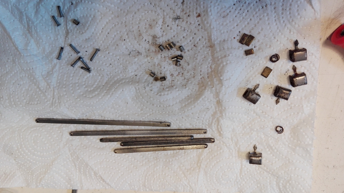
Disassembled again to now mount the tens' carry levers, intermediate gears and shaft. These are the parts all laid out, including the repaired tens' carry levers, which are all the way to the right.
Here they are mounted in position.
This caused some more shenanigans, because the locking arms for the counter gears are spring loaded, and the springs need to be hooked after a special shaft with a tab, that can easily be twisted too far, and then all the springs come loose and need to be carefully hooked back into place. In addition, two of the shafts are locked in place, not by locking screws, but by a tab that is pushed into two cutouts in the shafts and then screwed to the frame... like so.
Then I could thread the shaft with the intermediate gears through the tens' carry arms.
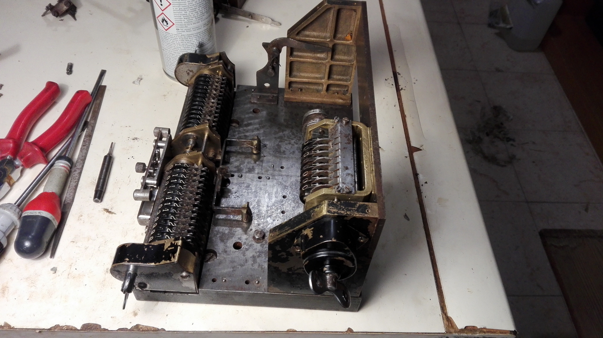
With this done and all the locking screws done up, it was time for the final straight in cleaning the few remaining parts that had not been cleaned up yet - the left and right uprights, with setting clearing levers and the main crank:
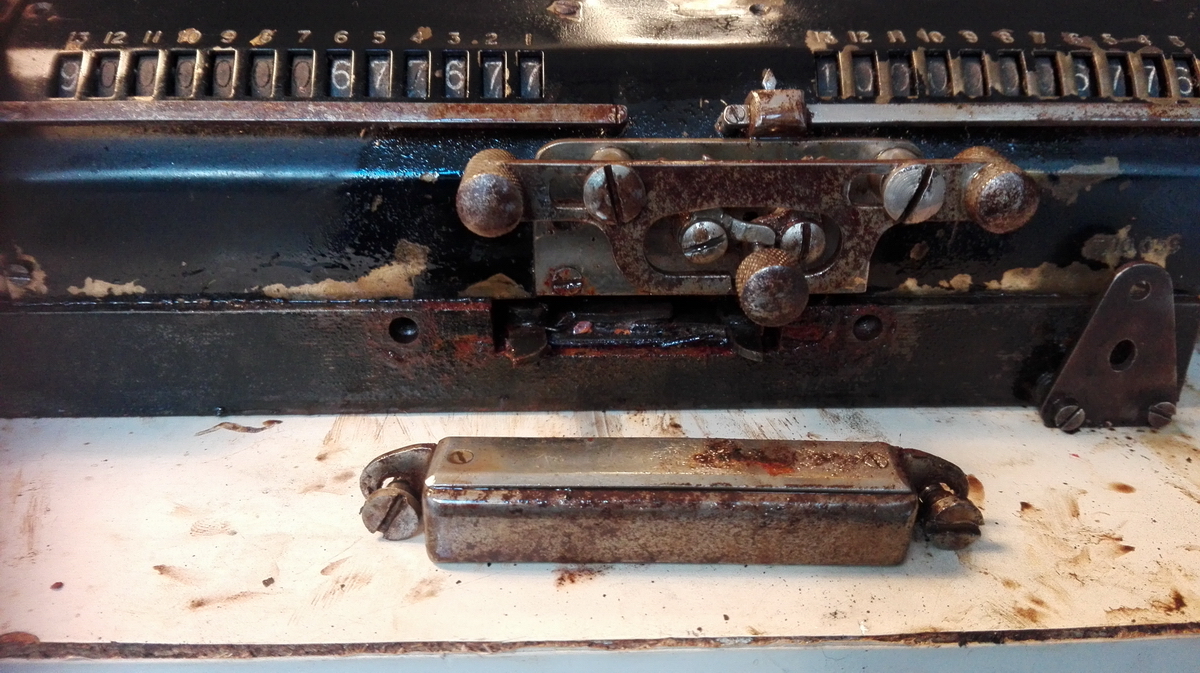
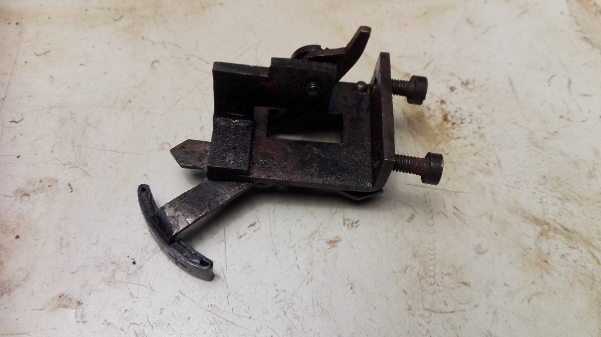
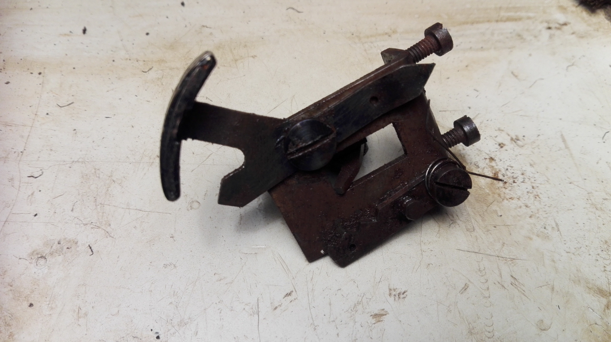
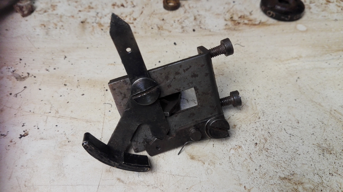
and finally, the carriage tabulator - this is before:
And after:
So then the time had come to put everything back together. I think that on a Duo Britannic, there is no other solution than disassembling the machine if you want the carriage out - logically, it follows that reassembly starts with the carriage and tabulator.
I quickly discovered that I had forgotten to clean the screws that go through the base, as well as the link between the carriage and the counter register. That omission was rectified quickly.
So then I had this kit of parts to put back together - or at least so I thought.
Carriage in ...
...rear frame and counter in place...
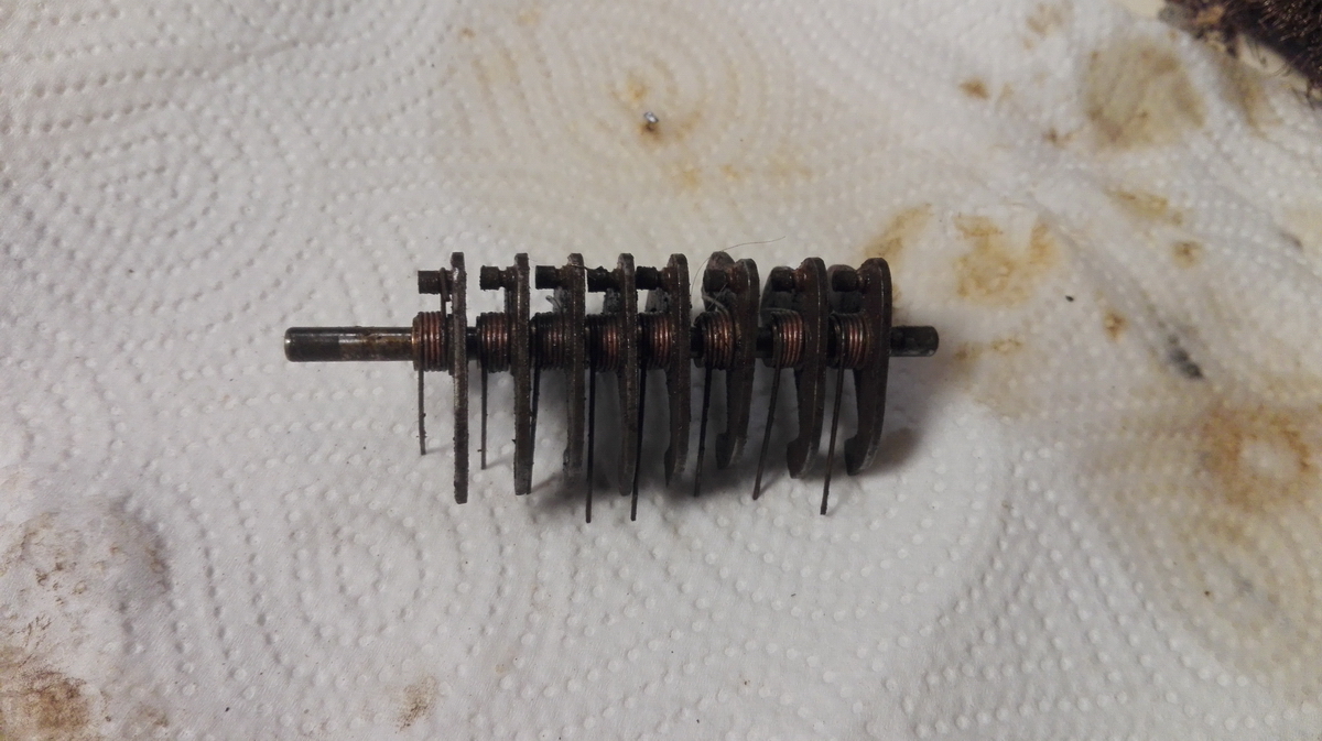
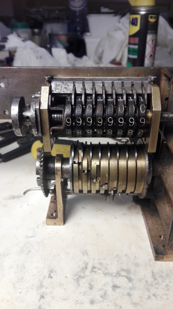
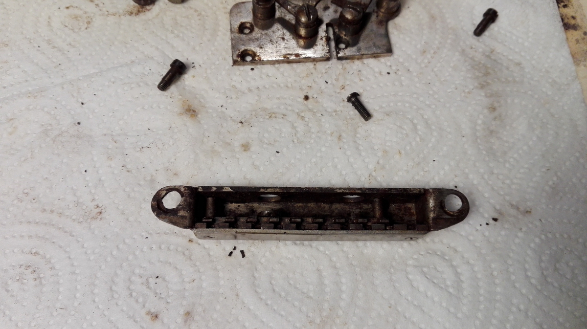
... and this is when I hit a snag. While I had verified that the tens' carry pins for the counter were free to move in all positions, what I neglected to check for was the actual counting pins - they are pushed out by a roll that pushes on a crest on the opposite side of the cylinder, as it passes by the counter gears. This only became clear when I mounted the cylinder back and tried it out. And these pins were all completely stuck. So out came the tens' carry cylinder, and here it is, all apart. You can see it is quite rusty.
You can also see here how it is supposed to work - the steel part has a spring on its "inner" pin, that bears onto the shaft that goes through the middle. The steel parts sit on a protrusion on the brass discs, so that they aren't clamped, but can be pushed down, so that the "outer" tooth, protrudes and engages the counter intermediate gears.
This is after cleaning:
And this is how it goes back together:
This is the crest and moveable tooth of disc nr. 4:
This is how the mechanism wit the moveable tooth works - demonstrazione!
And finally, it is back in the machine, and it is working.
So we remount the counter:
The clearing mechanism and wing nut:
Then the center block, which helps lock the counter clearing:
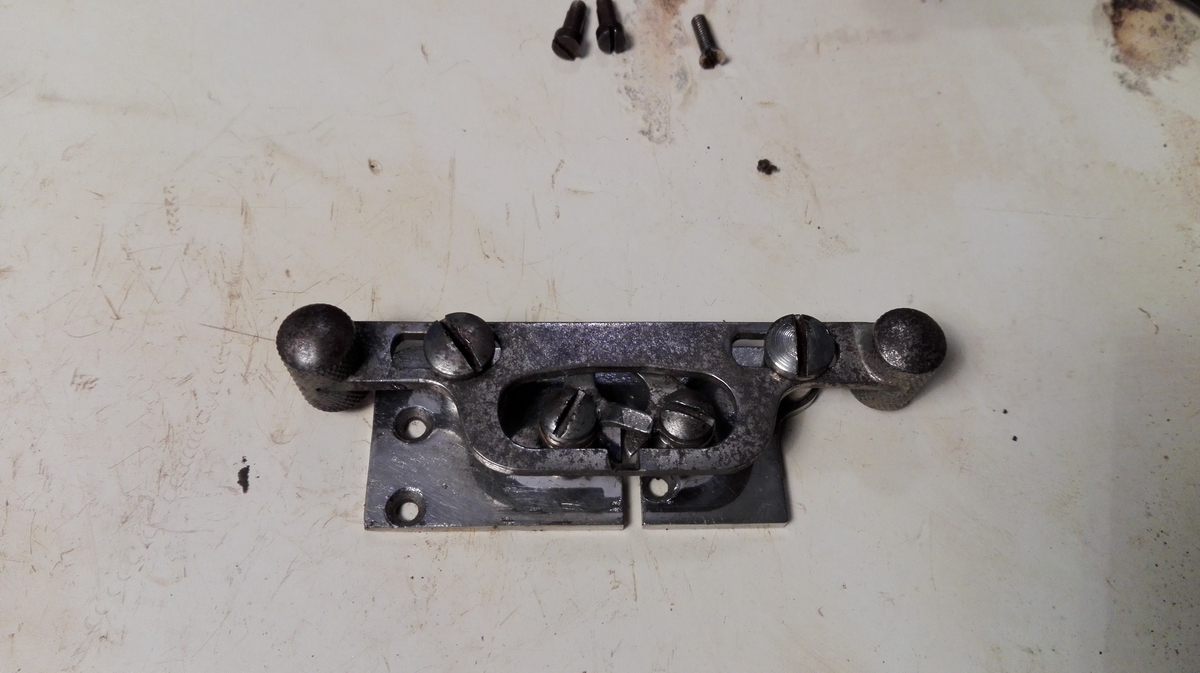
And then finally, I finished a five hour workday by remounting the direction change mechanism for the counter. This is quite ingenious, and makes sure by using a locking differential, that whatever direction the machine starts turning in, will end up being positive at the counter - the mechanism is reset into its neutral position by the counter clearing - for which is is also the security lock, the clearing can only be operated when the machine is in its rest position.
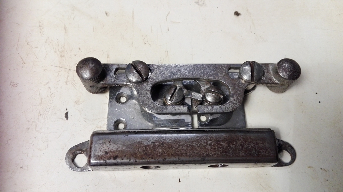
The next thing to be mounted back was the indicator for the counter direction, also a quite ingenious mechanism with three stable positions, that gets pushed into the + or - direction by a two-toothed cogwheel mounted to the counter axis, and reset by the counter reset leading to a vertical bar being pushed through a fulcrum into a different set of two pegs that push the thing back into the central position.
Next up - the differential gear for the main drive, and the direction selection lever.
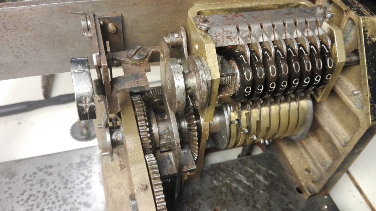
And then it was time to start putting the pinwheel cylinder and right and central upright back onto the machine - and this turned out to be a big problem.
There is a bar sticking out to the left which needs to be threaded behind the direction change lever, and hence the differential gear is in the way - that was a mistake that had to be removed again - and then, in order to get the central upright into its proper place, there is an interlock for the clearing of the carriage which engages with a cutout in the steel disk on the left of the pinwheel cylinder - but the trick is to get the central upright past this interlock. Once you get the hang of it (and you do get the hang of it if you do it about 10 times because something goes wrong every time ...), then it sort of works - the next issue is to properly register the gear on the left of the central upright with the drive to the counter, so that will be at its rest position when the pinwheel cylinder is also at its rest position. The other gear issue is at the right, where the pinwheel cylinder meets the upright, but luckily these gears are marked with the proper orientation, and with the direction control gear in place, the pinwheel cylinder cannot disengage from the crank gear anymore.
After ample faffing about - here's the result:
Then we put the differential gear back, and immediately ran into the next problem - it is impossible to mount the second pinwheel cylinder and the left upright as long as the steel stand on the left of the baseplate is still in place - this is the zero stop for the left pinwheel cylinder and the security that prevents a rotation starting if the security bar hasn't completely retracted to the right. So after keeping it here for the duration of the restoration, I still had to get it off in the end. The reason why I didn't do that in the first place was because one of the screws was rather stuck, and I had started to destroy the head. These cheesehead screws with a deep slot in the head tend to crack half of the head off if you use too much force, and then you're in deep trouble. Luckily the heads are so high that they can be grabbed with vise-grips, and then they are easy to crack loose, at the cost of deforming the head a bit. So - security off, and differential gear back in place!
Now we could mount the second pinwheel cylinder.
In order to get the security lock back in place, the left upright still needs to wait a bit.
Notice the washer under the stand... that clearly shows that something is fishy, and I discovered in short order that the gear on the right of pinwheel cylinder n°2 was off by a tooth, causing the zero position of the roller arm to be off as well. With the pinwheel cylinder rotated a bit, and the washer removed, all was well.
With also the left upright back in place, the final adjustment is this brass block, which prevents rotation of the left pinwheel cylinder when the security bar is not entirely retracted to the right. It needs to be adjusted so that the bar just interferes with it.
And that concludes the technical part of the restoration. The only thing I am currently not quite happy about is the tabulator. Both screws in the tabulator have stripped, and the toothed sliding bar in the bottom part is not held in place properly when the tabulator is mounted. This makes moving the carriage difficult. I will have to come up with a solution for that.
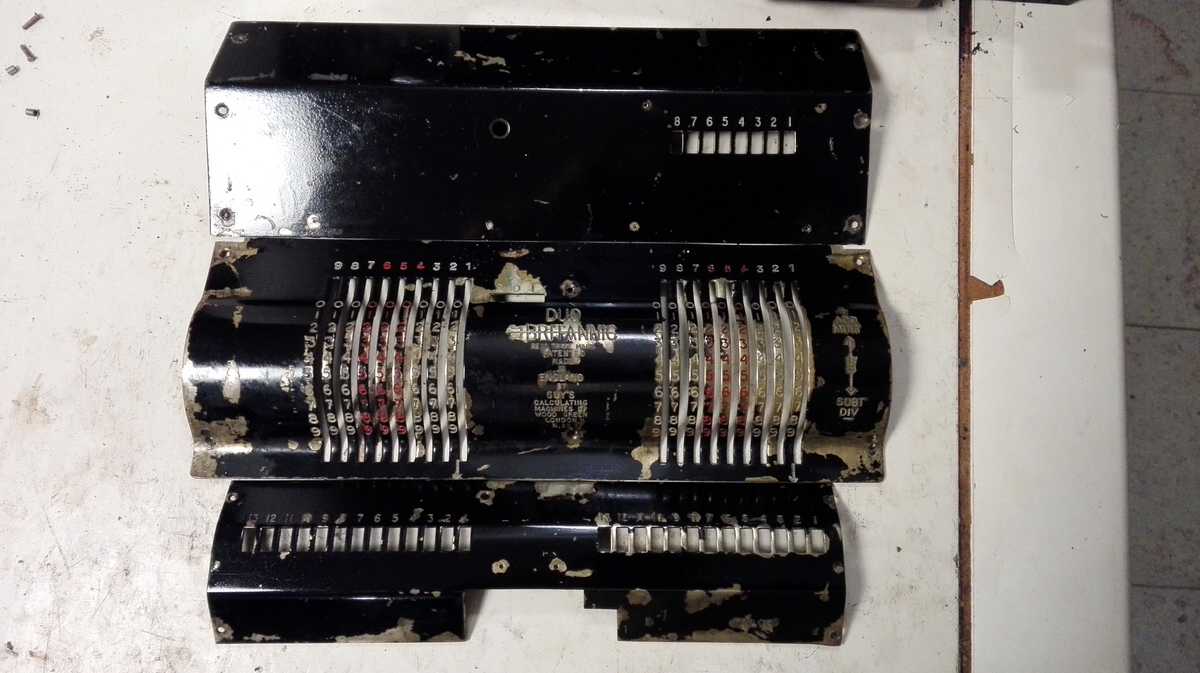
For now, this is a picture with the covers provisionally mounted, prior to restoration:
And finally, there's a video, so I can convince you that the machine in fact works properly ...
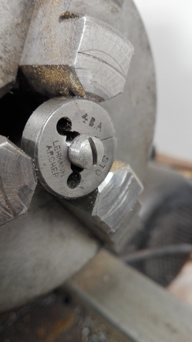
So then it was on to the cosmetics, and some more trials and tribulations. The first problem was that when disassembling in the very beginning of the project, I broke off a screw at the left result clearing cover, and I was unable to got it out. Since that cover is one of the few things on the machine that are fixed with only two screws, I really needed to be able to drill this out, retap, and replace with a proper screw. Since all the screws were rusty anyway, I decided to go ahead and buy stainless steel screws - but which thread were they? Luckily I was visiting a model engineering exhibition in London, and found a supplier who could run my scruffy looking samples of the original screws through a nut to verify they were in fact BA threads. And they were - 10BA for the comma indicator rails, 8BA ofr the cover screws, 6BA for the back cover, and 4BA for the hold down screws at the bottom of the baseplate. However, I only needed 1 4BA screw, and the smallest package available in 4BA cheesehead screws was 25 - for £10. I was not going to pay £10 for a single screw. I knew of someone in Belgium with a full set of taps and dies for BA, so I just made the one 4BA screw ...
The covers were cleaned up:
The numeral wheels given a lick of paint (especially the zeroes ...)
And then I ran into technical issues again. The machine has a timing issue. I was convinced that I had misaligned the crank by one tooth, but after taking the machine apart again and switching it one tooth, the problem just moved to the other side of the crank rest, and was even a fraction worse. The problem manifests itself by the result register being unable to be cleared with the crank in its rest position, and the machine not being able to switch direction from equal to opposite rotation of the pinwheel cylinders without pulling out the crank and pulling it forward a few degrees. It appears as though the crank was drilled incorrectly, or the pin used was incorrect - the crank has definitely been removed and put back in past. I managed to minimize the error by taking it off, twisiting it and repinning, which made things a bit better. Only the clearing of the counter register is still slightly iffy. But a disassembly like this, to mess with the timing of the machine, always has dire consequences - countless times, things will go wrong when putting it back together, because the only way to learn how to do it properly is by making mistakes. So when I finally had everything back together and was able to reotate the machine effortlessly in all directions and clear the registers etc ... I then found that the setting pins didn't free up, so I had to start over.
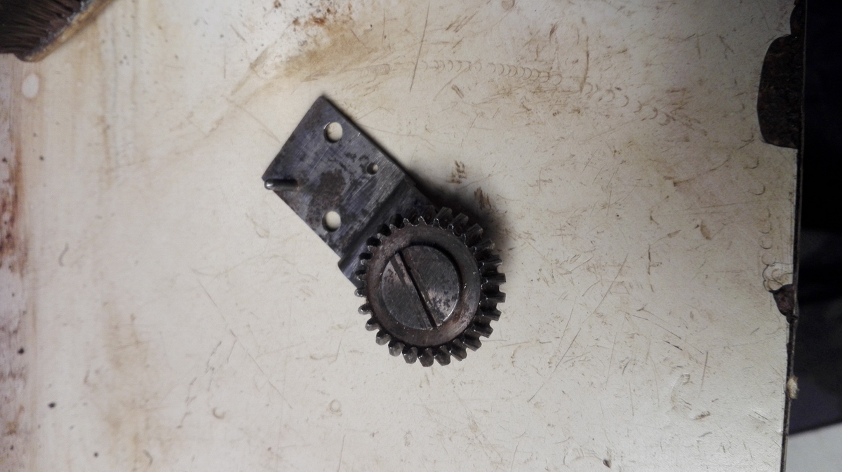
Another interesting observation stemmed from the fact that the selection lever for the machine directions was completely free to move and would often disengage halfway through a turn. The reason for this is that apparently a part of the machine is missing.
As you can see on the top surface of the central rest in front of which is the selection lever, there are two locating pins and two holes drilled 8BA. So I made a strip of brass with the proper holes, and filed three notches in it to locate the lever by its own springiness. It works great.
And that really concluded the technical restoration. Now it was on to the comma sliders and rails:
...and finally putting everything back together.
And then, it was time to mount the beast back onto its base plate and installe the cover, and it was picture time!