Brunsviga N
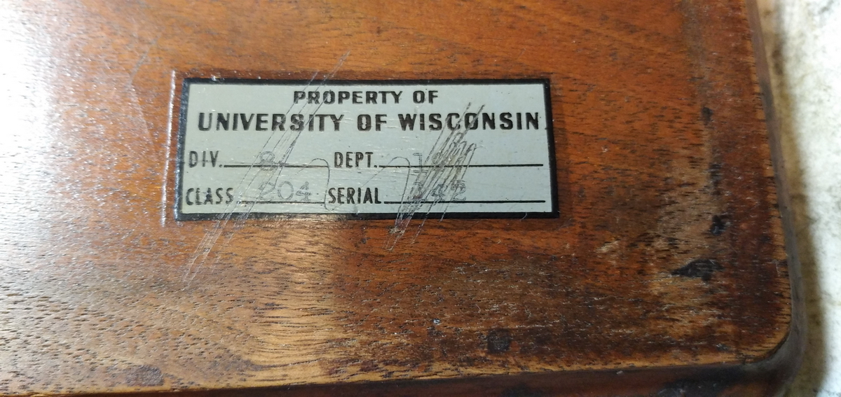
This machine too is rare as hens' teeth. Only 141 were built, in three series in 1910-1911. Known serial numbers are 16411 (in the Brunsviga collection/ the BLM - probably the first one built), this one, N° 16975, then 18807 and 18808, 18817, 18821 and 21584. According to Brunsviga records, it was built until 1915, and then again in 1919 (but possibly only 3 examples then - a special order, perhaps?). This one came up for auction at an auction house in California, and the first owner had been the University of Wisconsin in Madison. What research it has been used for there in 1910 when it was built and ordered from Berlin, remains anyone's guess, but it is a safe bet that it would have involved multiple products somehow, because that was the one unique feature of the Brunsviga N that no other calculator in the day was able to offer: backtransfer from the result register to the input, making the calculation of cubes and continued multiplication easy. In the words of a contemporary advertisement: "carriage is moved one place beyond units position when zeroising, throws up the product to figure plate for further multiplication"
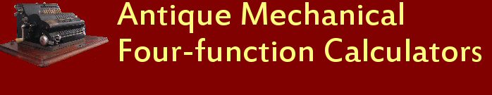
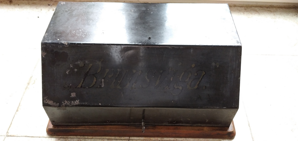
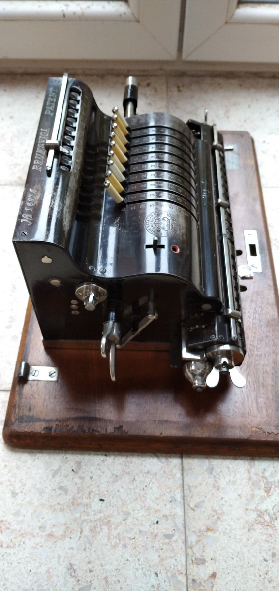
This is what it looked like on the auction site:
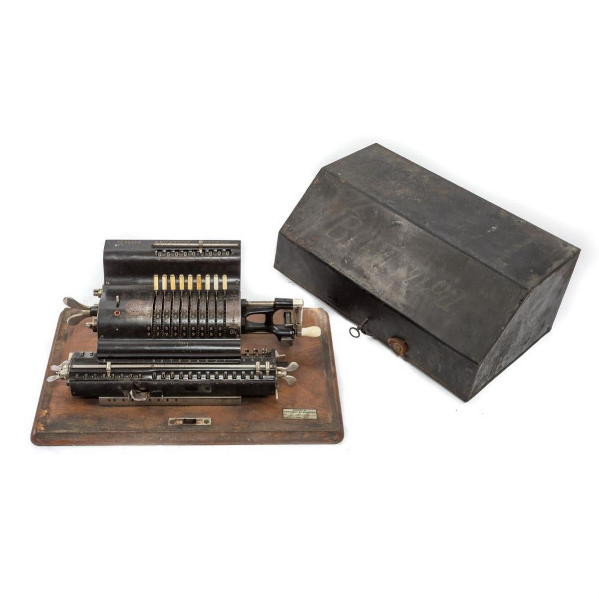
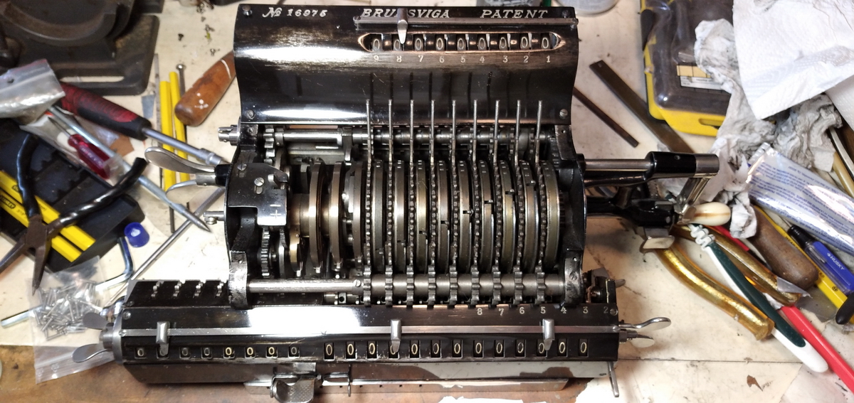
And when it arrived here, I could not resist opening it up immediately to see how the backtransfer works - in fact, I sort of had to open it up, because it didn't work at first.
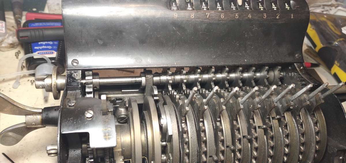
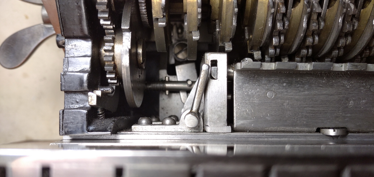
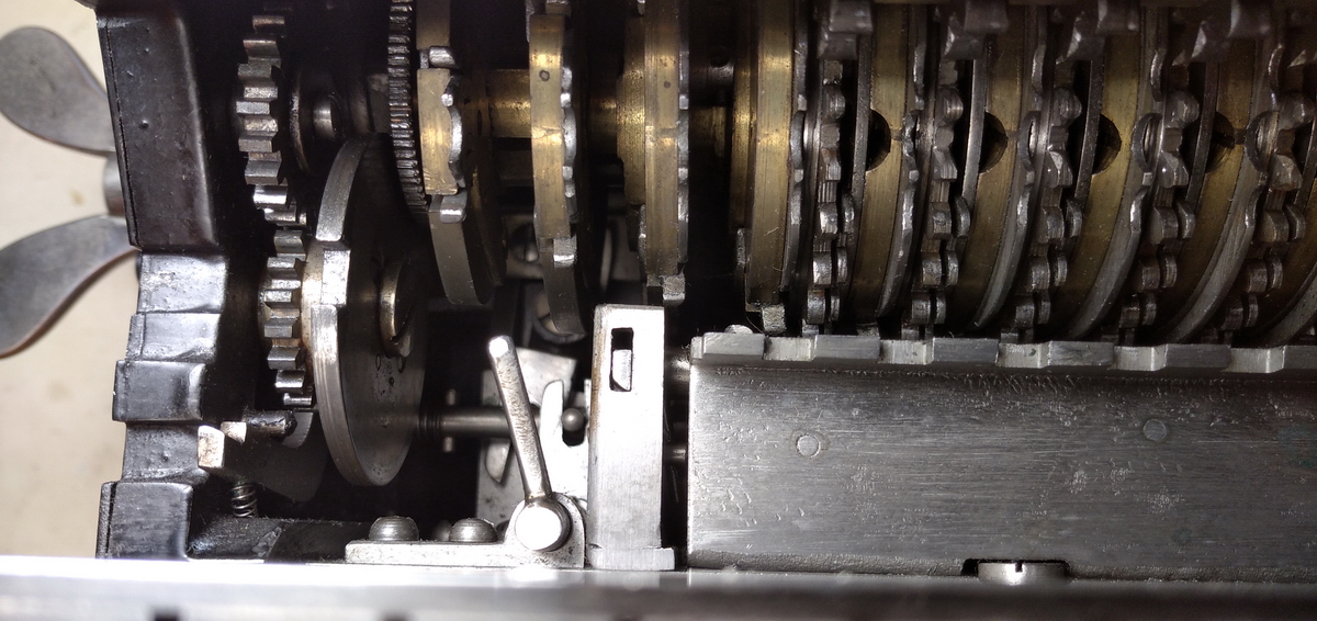
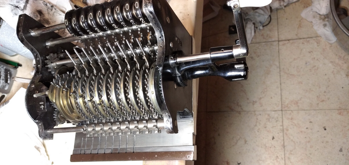
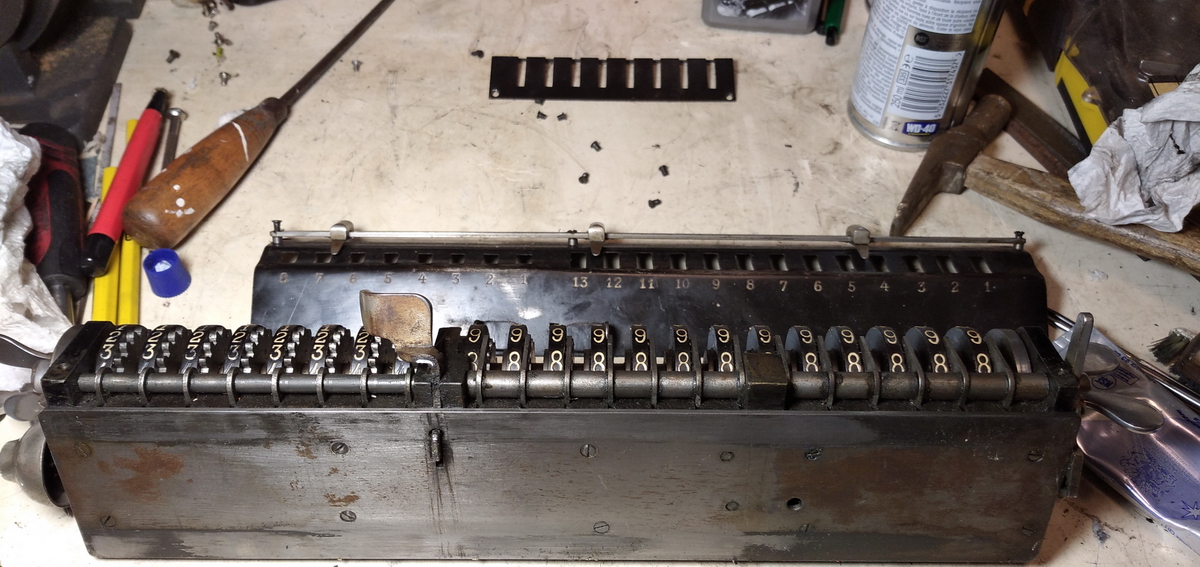
Backtransfer operates, as you can see from the picture, by first resetting the setting register, and then unlocking the carriage stop with the lever on the right side of the carriage. The carriage can then be pushed left by about half a digit and locks there, also unlocking the setting pins in the process. In principle, now the result register can be cleared with the wingnut on the right, and the number should transfer to the input register and show up at the top of the machine in the input control register (which is on top here, as opposed to in front of the input in the "normal" non-moving lever Brunsviga machines. That, however, did not work.
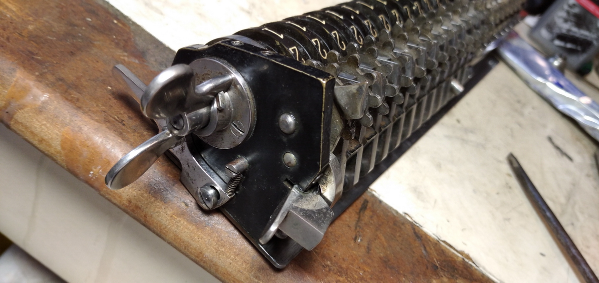
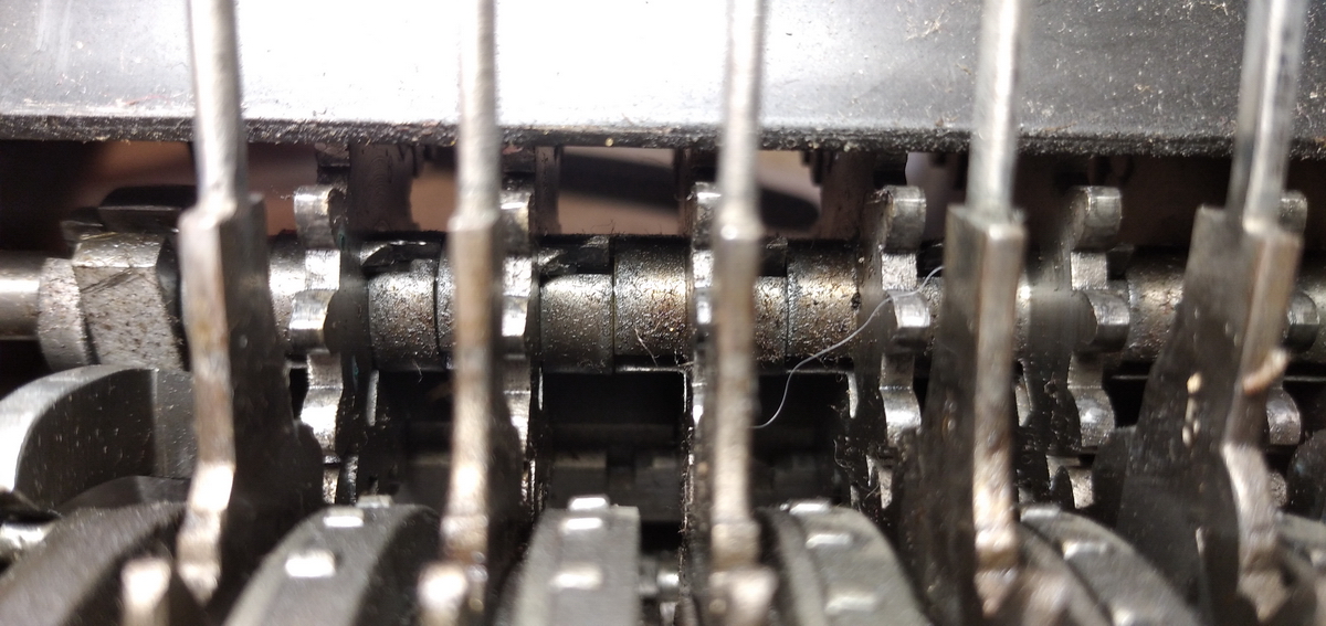
There is a lever at the back of the carriage that moves backwards when the wingnut is turned, doing nothing when the carriage is in its normal position, but when in backtransfer position, it operates a complicated system of levers and bars in the back of the machine, to ultimately culminate in a lever pushing downwards next to the tenth disk in the pinwheel cylinder, there twisting a rod that runs into disk number ten. What this does is to remove the detent action from the input levers. In normal operation, when they are being set, they "click" into every position. For backtransfer, this is undesirable, as the action needs to be as light as possible - so that is what this lever is for - removing the detents.
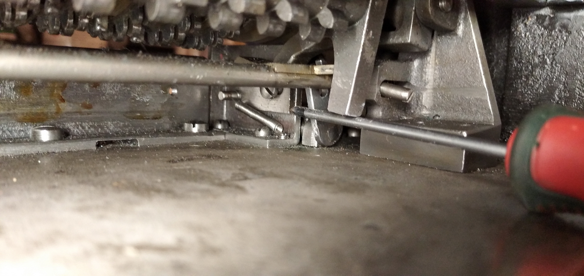
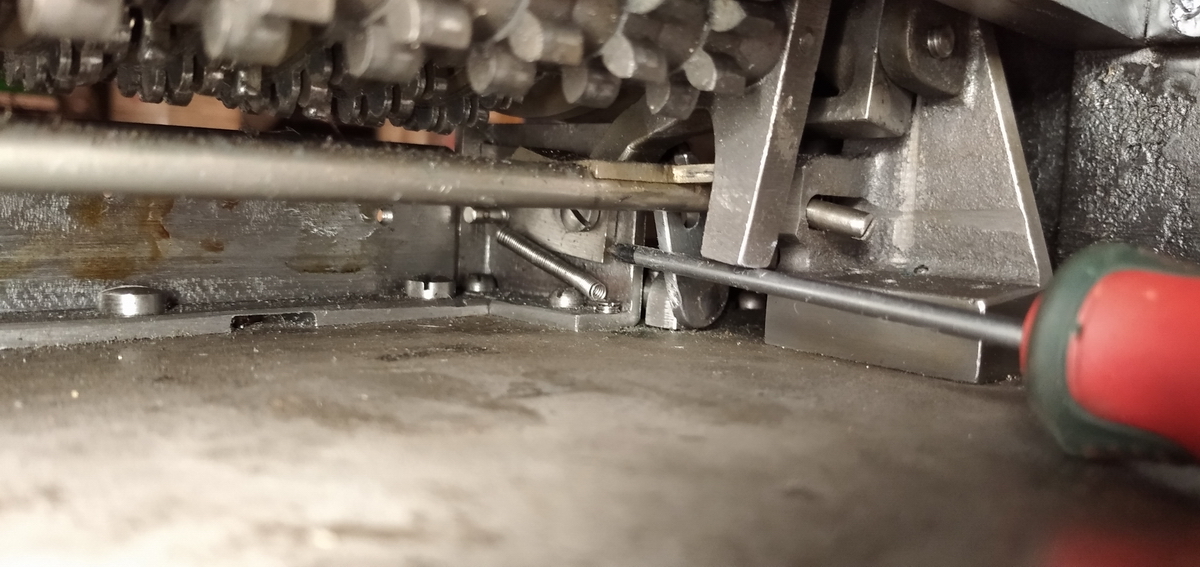
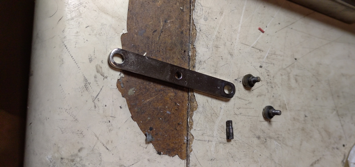
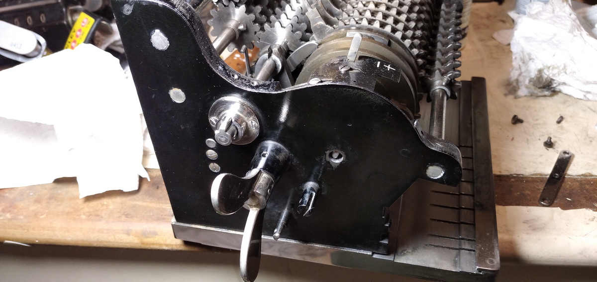
This whole system appeared to be stuck, preventing the register from being cleared when it was in the "backtransfer" position. It turned out to be a screw that was too tight on one of the levers screwed to the right upright of the machine, locking everything in place. So that was somewhere here:
With this loosened, the backtransfer worked without issues.
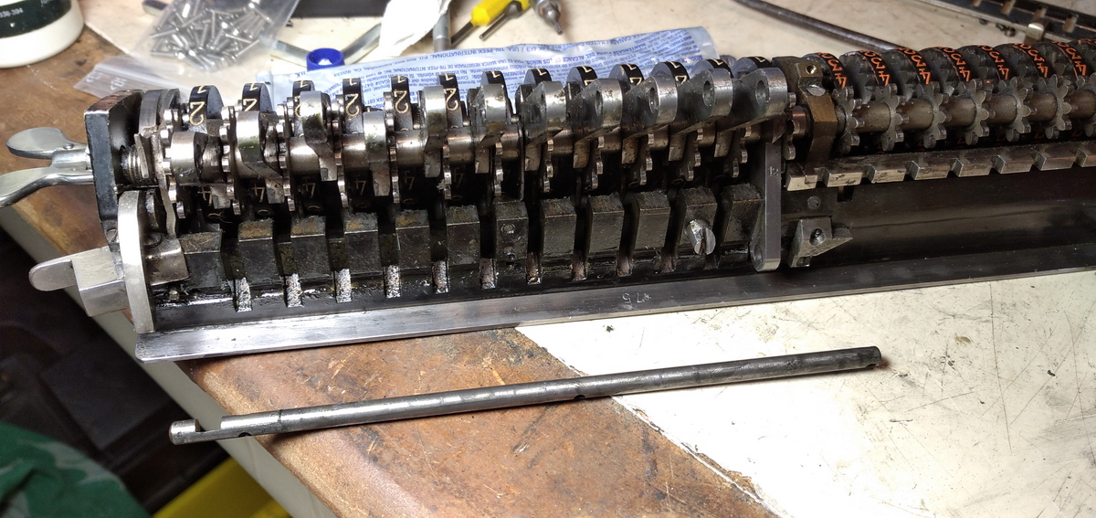
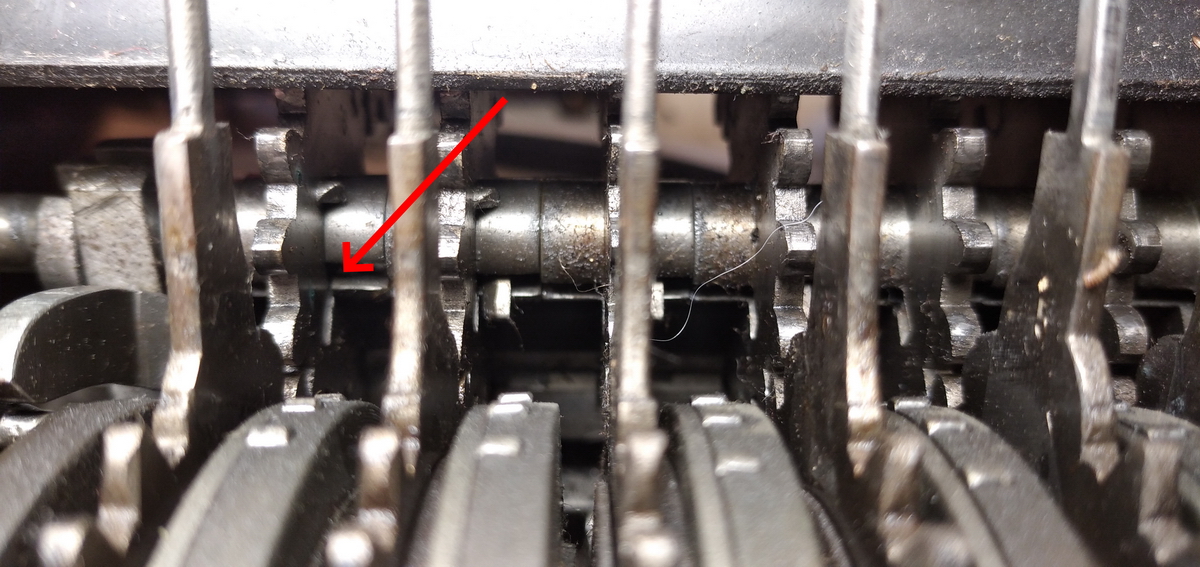
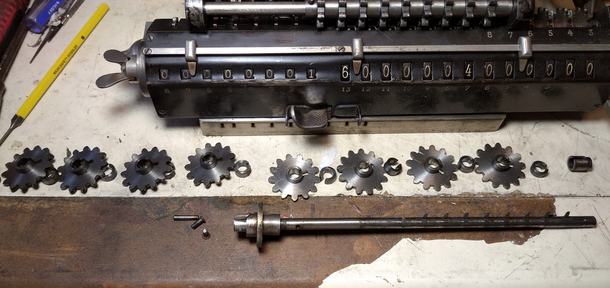
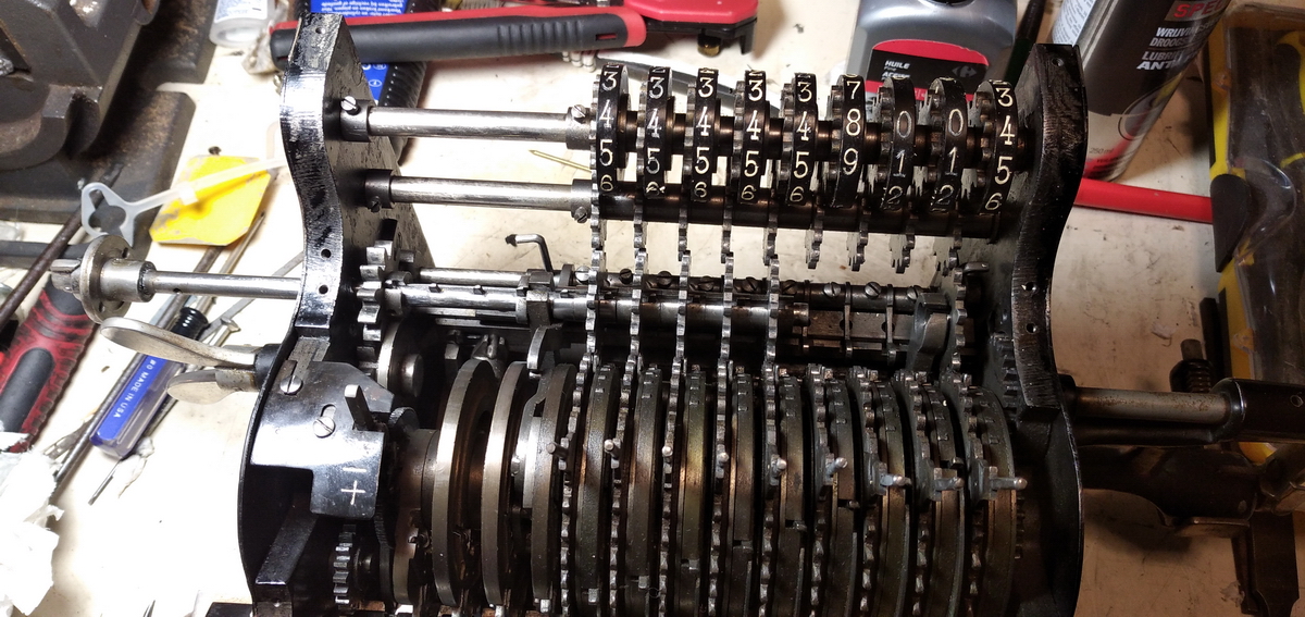
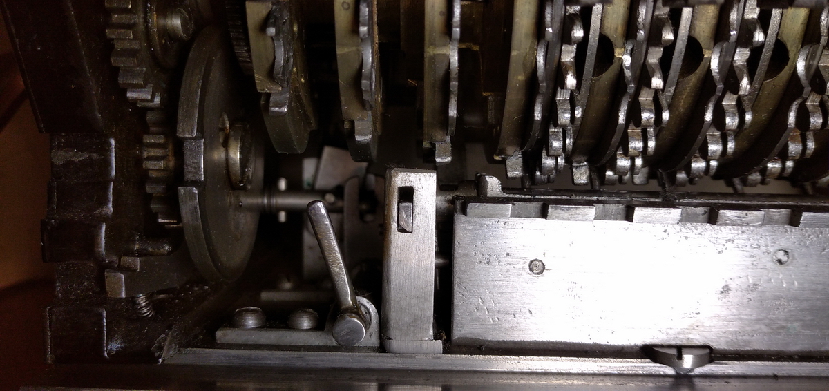
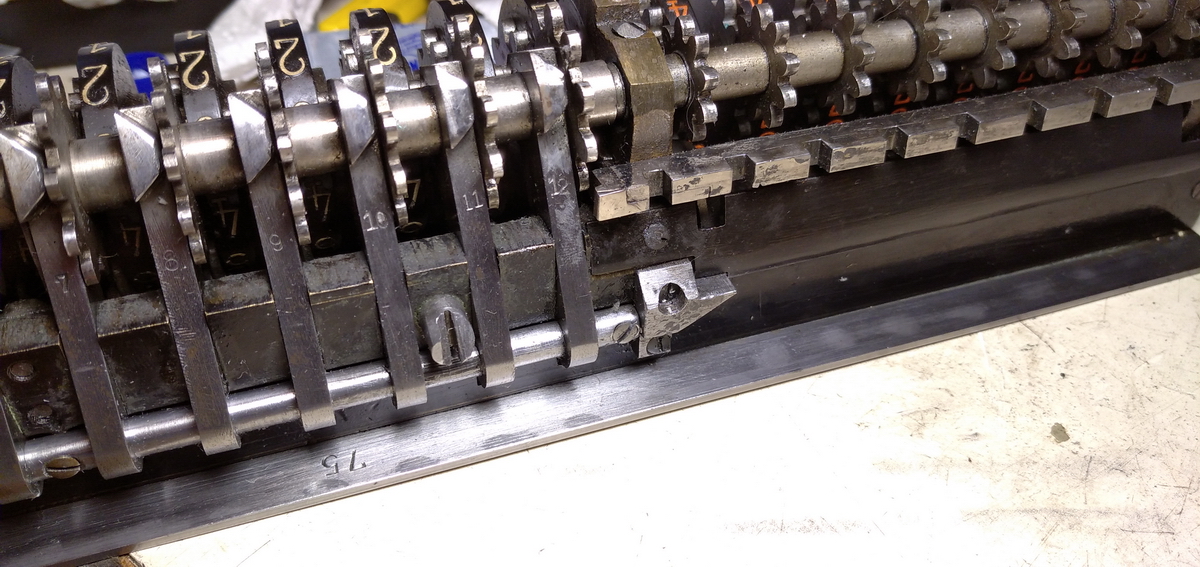
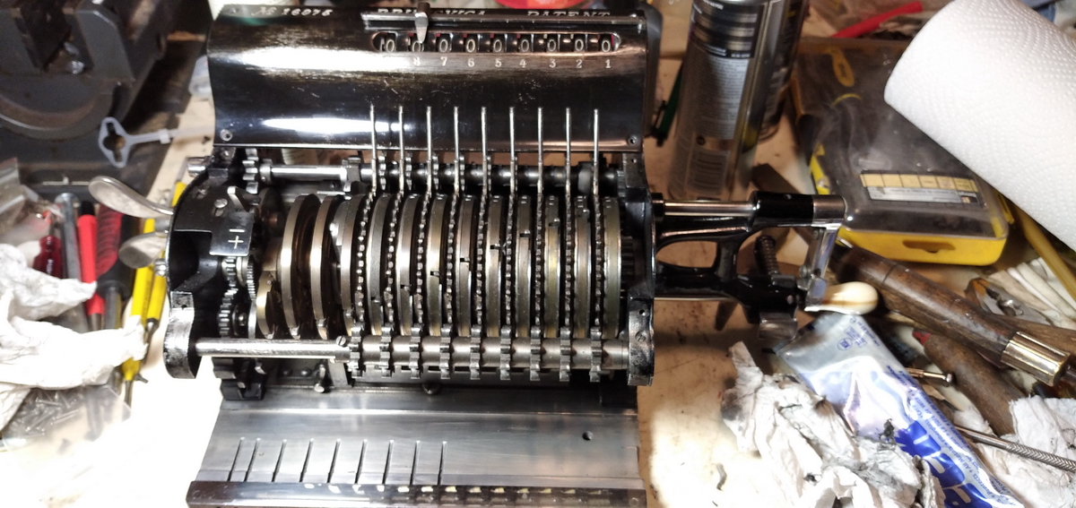
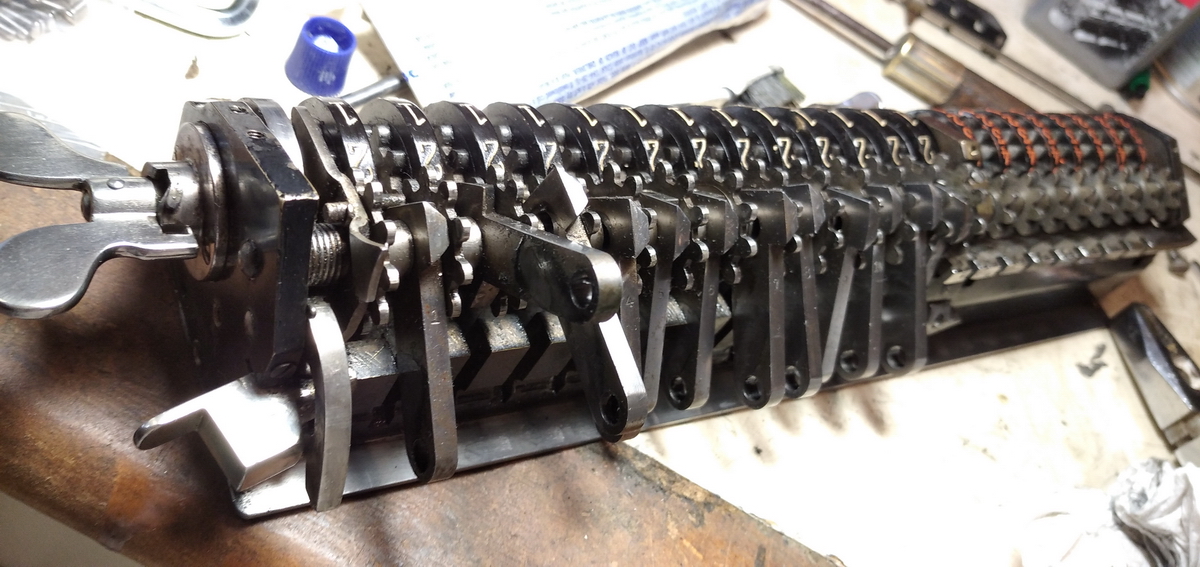
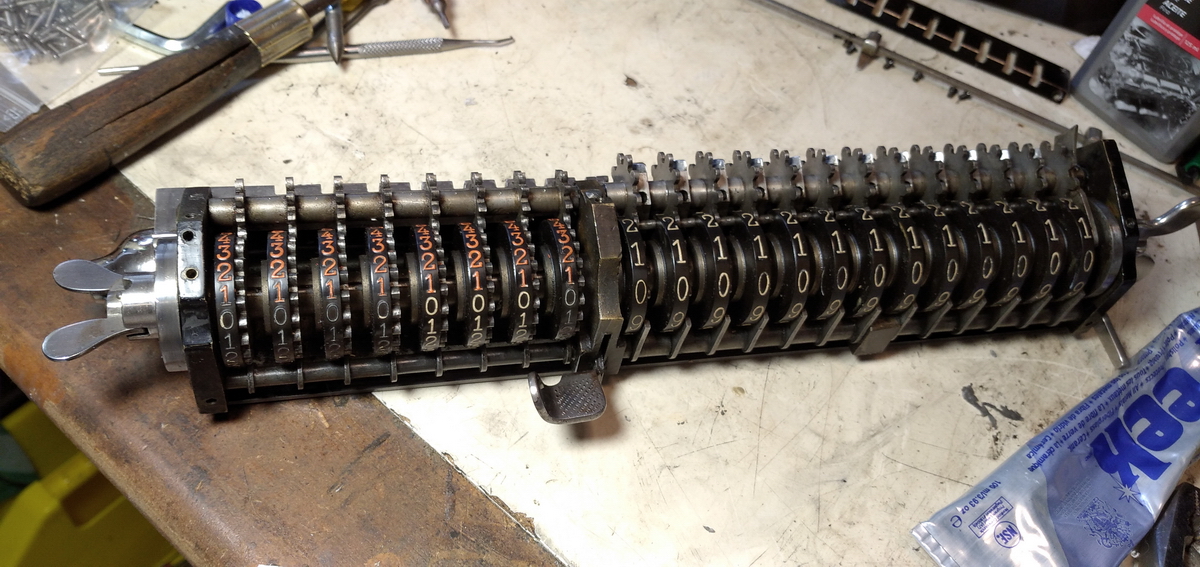
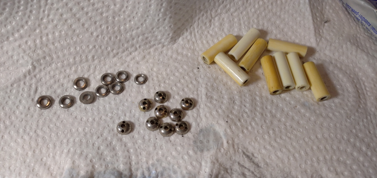
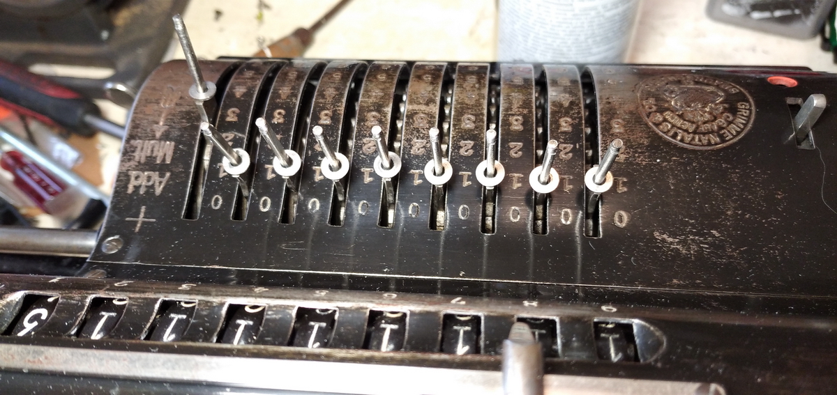
But it then turned out there was another issue. Before a backtransfer is made, the pinwheel cylinder should be zeroed, and this can be done with the (very) large wingnut at the left side of the machine (in the other fixed input lever machines, this is done with a lever, the Brunsviga N, however, always kept its giant wingnut). It turned out when testing this that the leftmost setting pin would not reset at all.
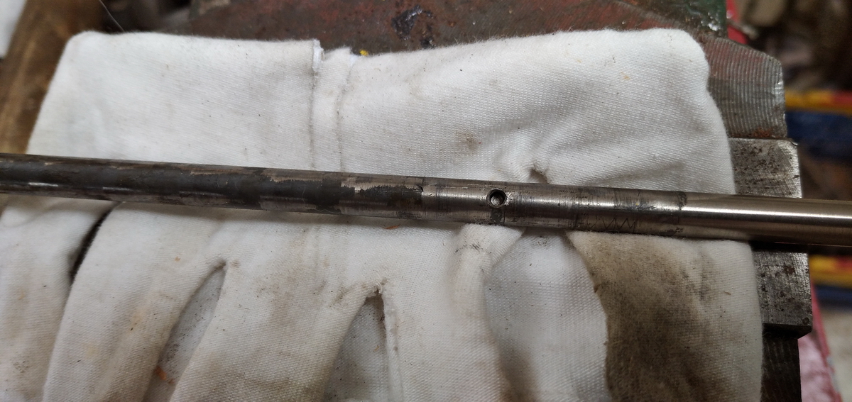
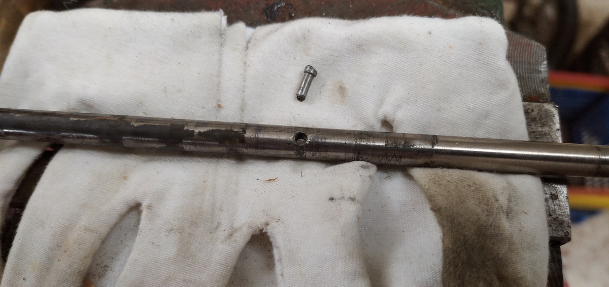
No big wonder, the pin that takes care of the reset action was broken off in that position, as can be seen from the pictures below.
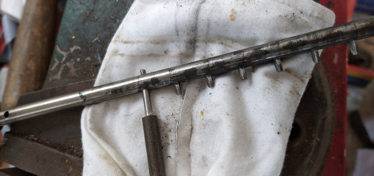
This would not do, obviously, and would need to be fixed. I was afraid that I'd have to take the entire machine to pieces, but luckily that was not the case. The main impediment to taking this axis out is this gear that is pinned to the axle. The pin can be reached with a drift and carefully tapped out

... like so.
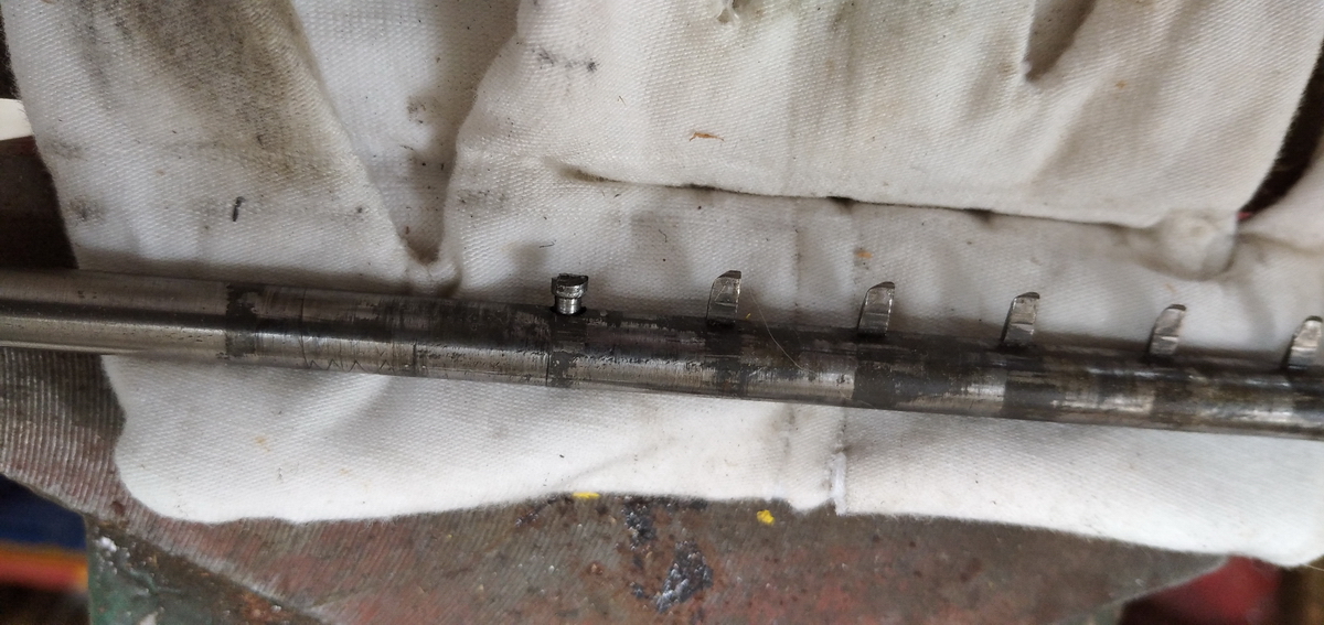
Then all input pins have to be set at 4, and all the intermediate rings lined up so that the pins can pass all the lined-up cutouts. When the screws at the left end of the axis are undone, it can simply be slid out.
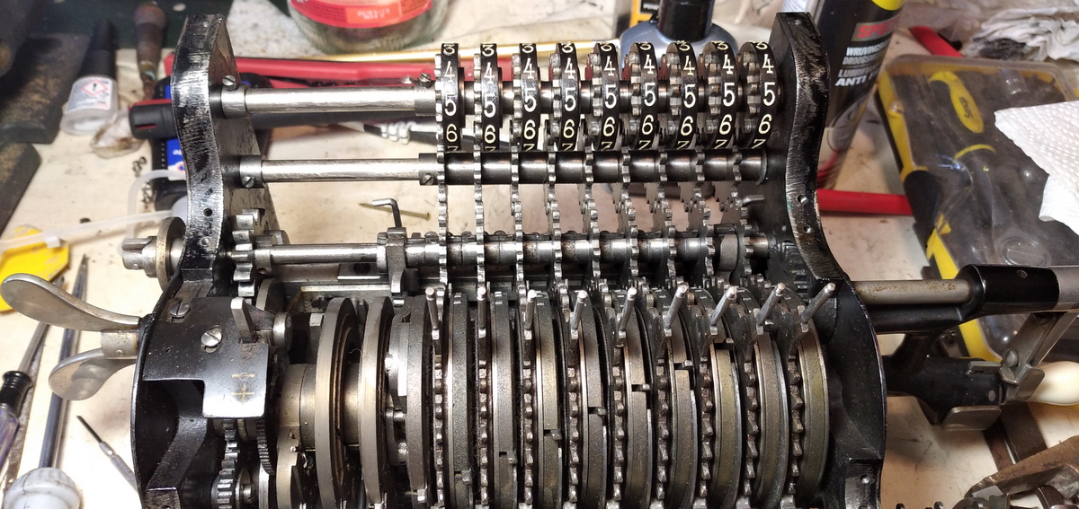
The first gear on the right is more or less captive, or at least very difficult to remove, but the rest falls apart quite easily.

The damaged tooth can be tapped out from the back, like so:
...and a new one had to be turned on the lathe (from a nail - shh!)
After cutting off the rest of the nail, the tooth has to be filed to shape


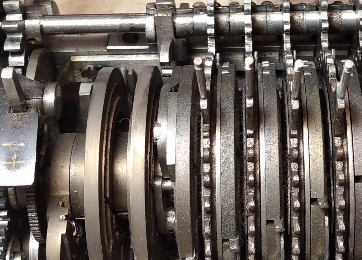
And then reassembly is the reverse of disassembly, with the added difficulty that now the gears and spacers need to be carefully placed back one by one as the axle is pushed through, taking care to correctly line up the 4 in the input control register with the gear as the input lever is also on 4 to line up the slots for the teeth. It also becomes obvious that the input control register wheels are a bit special - the intermediate gears have 12 teeth, and the numeral wheels 11 - so not all positions on the numeral wheel are used, there is a "gap". These numeral wheels, I believe, are unique to the Brunsviga N, also for having their gear on the "wrong" side.


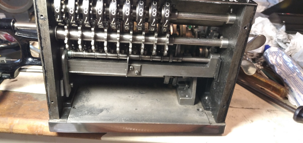
Looking at the back of the machine, it is mostly empty - none of the mechanism for the top counter register that is present in all other fixed input lever Brunsvigas is necessary here, because the counter register is in the carriage. All the gubbins that are visible here are safety mechanisms and interlocks. Most of what is visible helps with the transfer of the movement of that famous lever at the back of the carriage we talked about higher up, along the right side of the machine to the axle below the intermediate gears in the picture, and then on to the lever next to pinwheel n° 10, which ultimately removes the detent action from the input pinwheels.
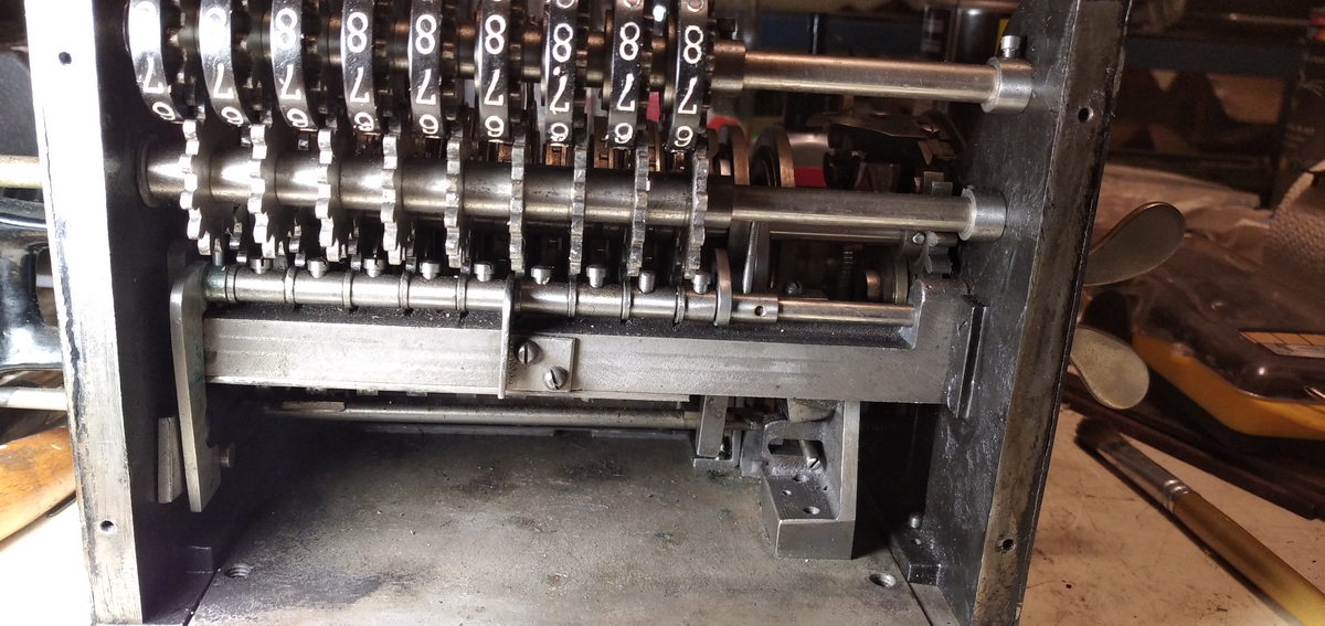
All the rest visible in this picture are safety interlocks, and there are quite a few in a Brunsviga N. While the pinwheels are rotating, the setting wheels and levers are held into place via the sprung blocking teeth interlocking with the intermediate gears for the setting mechanism - they rotate along with the axle for removing the detents on the setting levers, the lever inside the pinwheel cylinder does the same for the actual pinwheels.
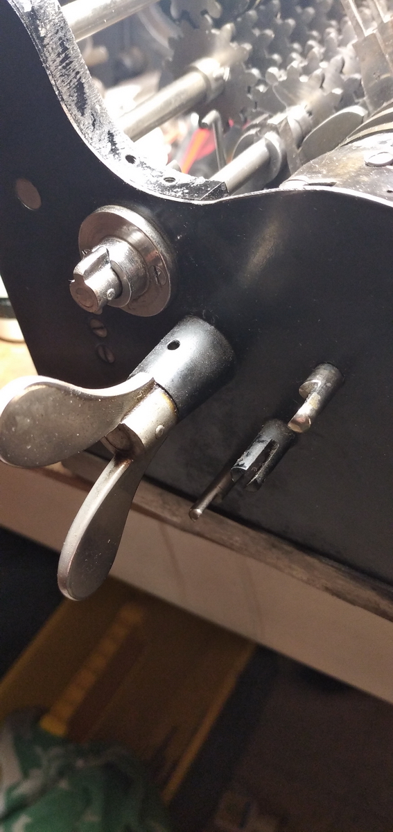
And then there is this, sitting screwed to the back of the vertical plate that takes up all the real estate under the pinwheel cylinder itself:

That plate seen here from the front:
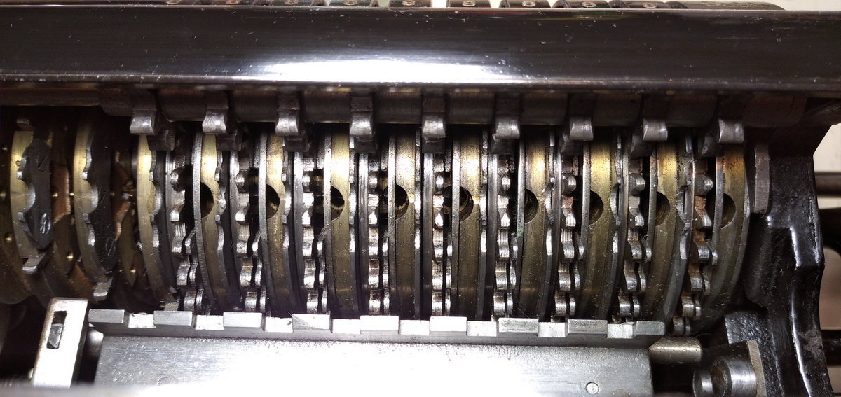
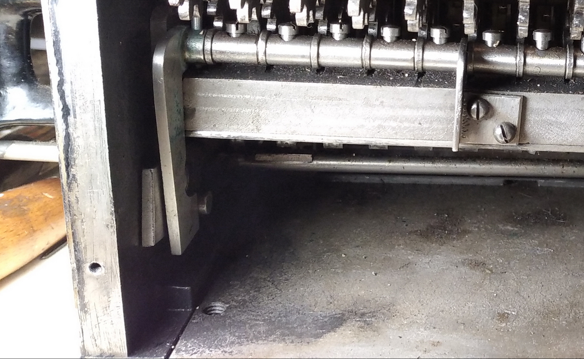
The feelers on this axle go to every pinwheel, and essentially feel whether the input lever is at its zero position. If any of them isn't, the feelers are pushed downwards, which pushes the bar at the right end forward. The effect of this is the following:
and seen from the front:

The result of this little pin coming forward is that the carriage cannot be shifted to the backtransfer position.
This can be understood looking at the back of the carriage, and there is more that warrants an explanation:
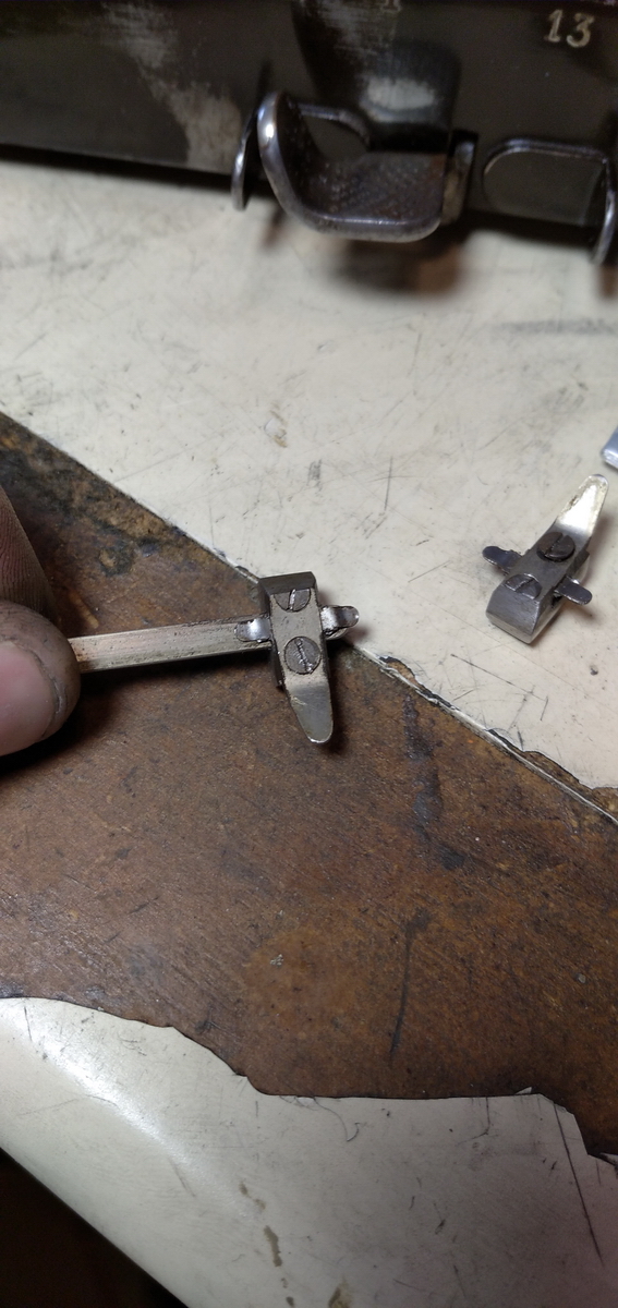
There are two features here - the arrow shaped steel piece on the right, and the filed screw sticking out the back two positions to the left.
Apart from the interlock butting up to the filed edge of that screw, preventing the carriage from going into backtransfer position when the input is not at zero, their effect can be seen in these pictures:
The filed screw pushes this lever over to the right when the carriage is in backtransfer mode. This operates the release mechanism for the input pins in the same way the clearing wingnut does, of the thumb button under the main crank.
The arrow shaped piece on the back of the carriage pushes down on the steel lever you can see disappearing into the back of the machine at the very left of the picture. This locks the input clearing wingnut, so that it cannot be operated while the machine is in backtransfer mode (or vice versa - backtransfer mode cannot be engaged when the clearing wingnut is not in its resting position).
I've made a small video demonstrating all of these interlocks:
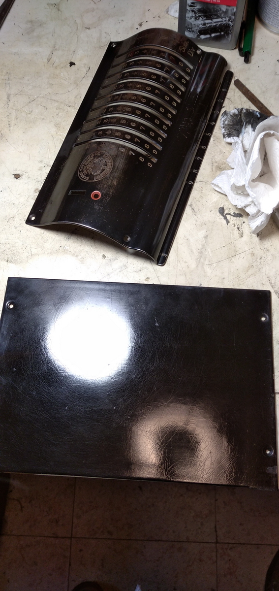
Now, with the input clearing repaired, it was on to cleaning and polishing.
...a lot of cleaning and polishing.


The back of the comma sliders in the carriage is screwed together and then the back is ground away (with half of the screw) in order to clear the top plate.
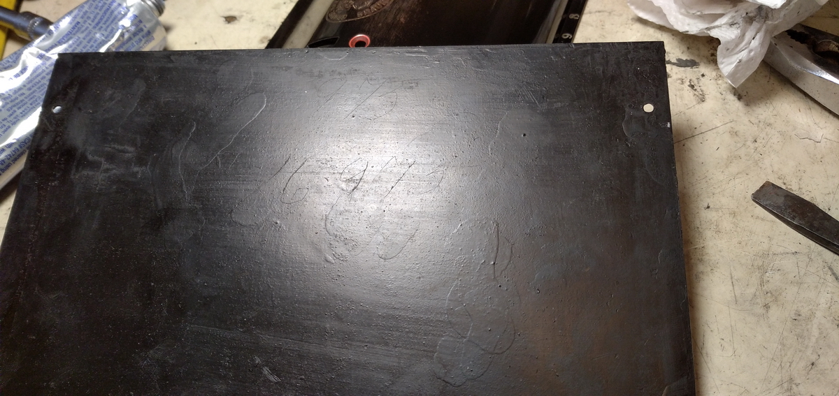
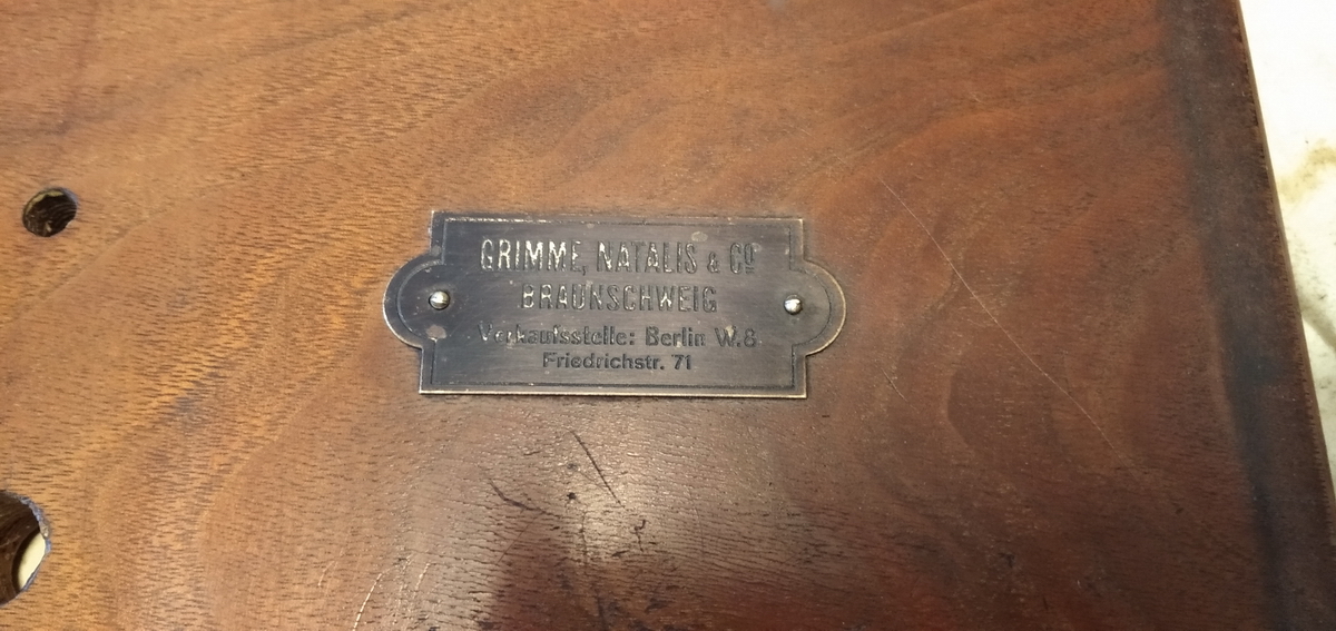
This is also interesting - in the factory, the serial numbers were scratched into the paint on the inside of the panels. It turns out this panel was apparently first destined for machine number 16973 - then below, 16975 was scratched in. Either that, or the University of Wisconsin actually bought at least three of these machines, and this was done during maintenance. Probably unlikely, given the European shape of the 1's and 7's ...
Shiny!
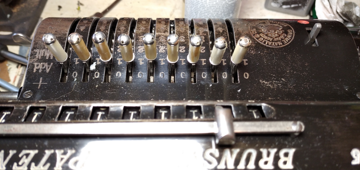
When all the machine components were clean, I moved on to the input levers.

Then the base plate, and the metal cover.

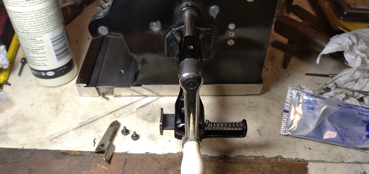
Finally, the machine was mounted back onto the base plate, with the original felt in place.

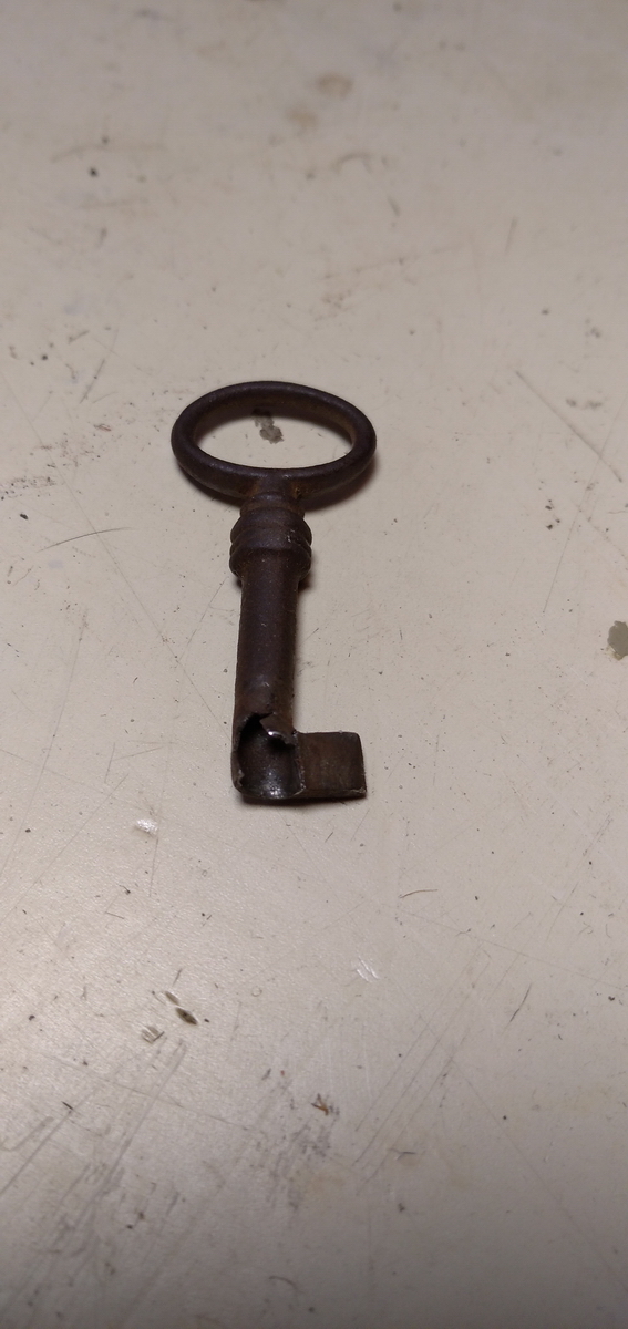
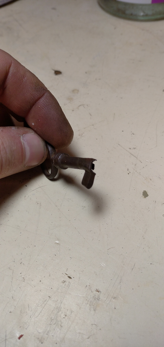
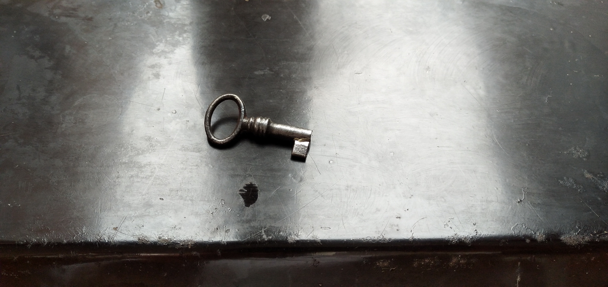
The final piece of the puzzle was the original key, which was in a bit of a state. I ended up making it a bit shorter and silver soldering the original beard back onto the original key.
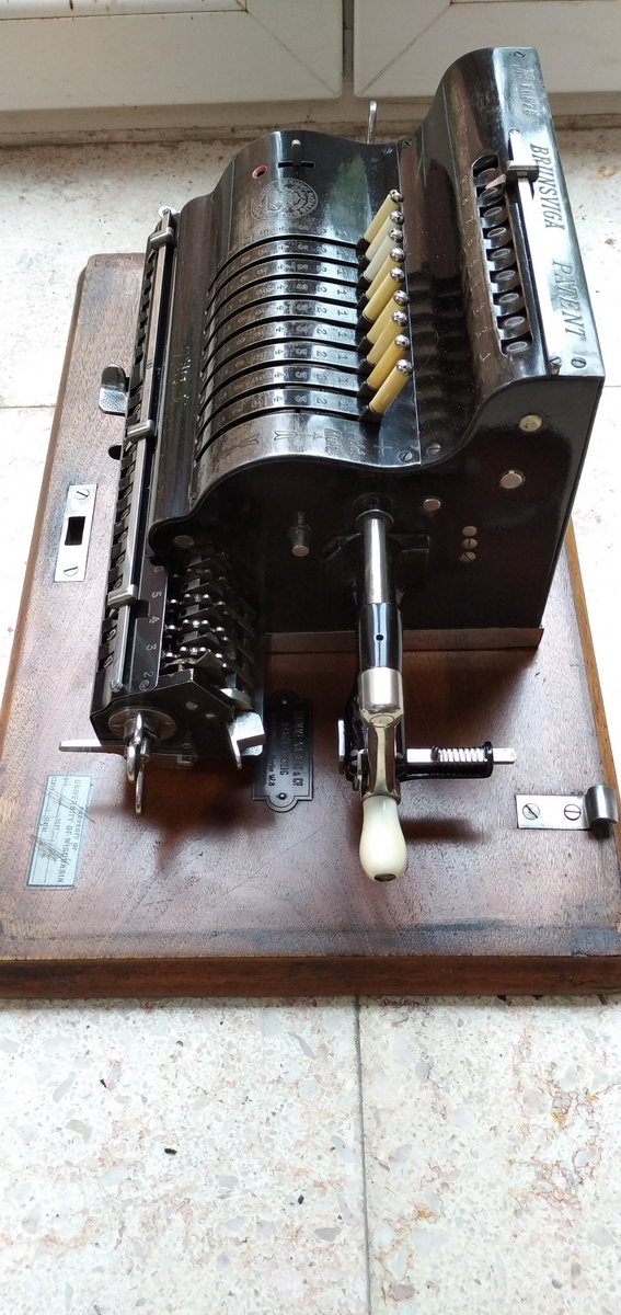
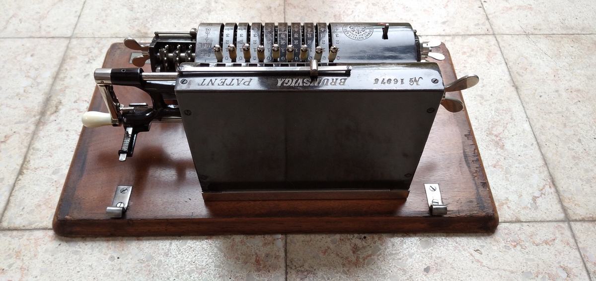
These are some beauty shots of the machine:
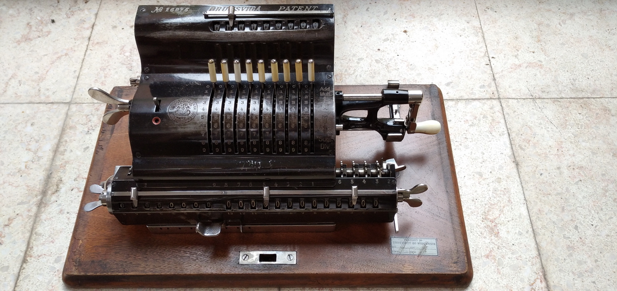
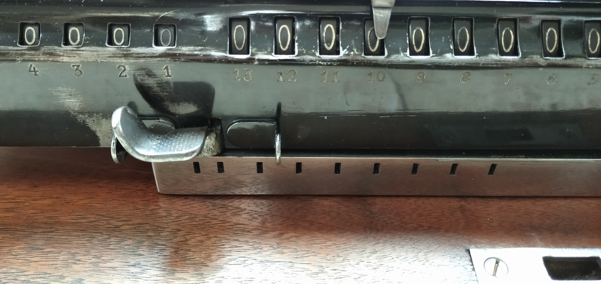
The extra "half step" carriage position on the left for backtransfer is clearly visible here:
And this is the carriage in backtransfer position:

Finally, a video of the machine in action:
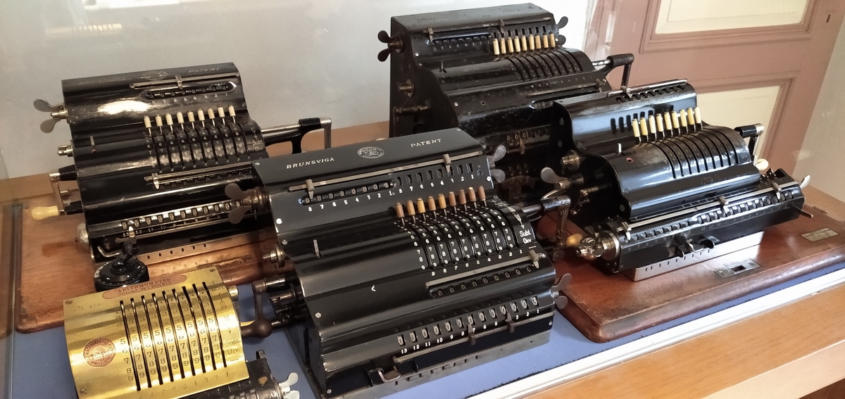
I could not resist putting it in the display cabinet with its fixed-lever brother and sisters. This is probably the rarest assembly of Brunsviga calculators anywhere - From left to right in the back: Brunsviga K, Brunsviga G - in the front (apart from the early Odhner) Brunsviga H and Brunsviga N. The display cabinet would not have been out of place at the distributor in Berlin in approximately 1912 !