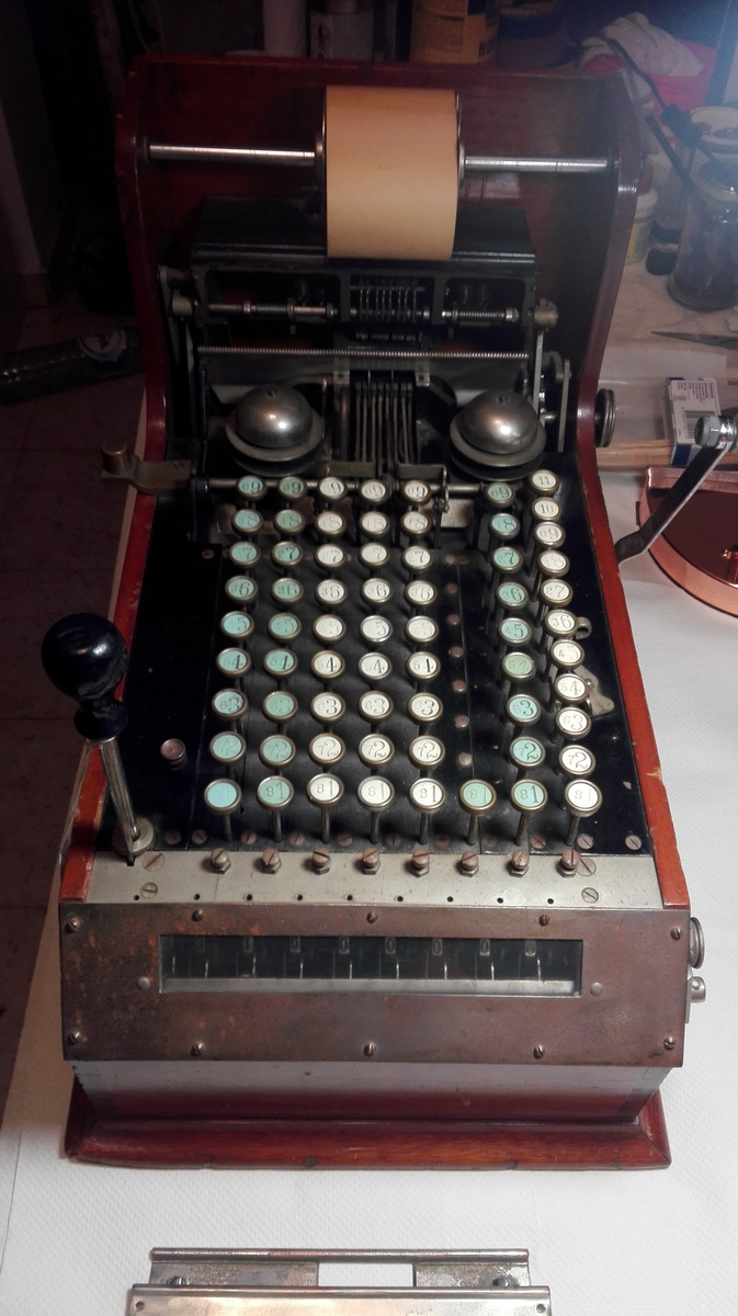
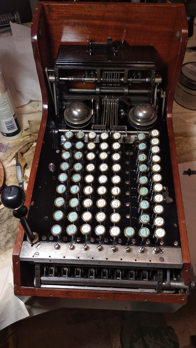
Comptograph
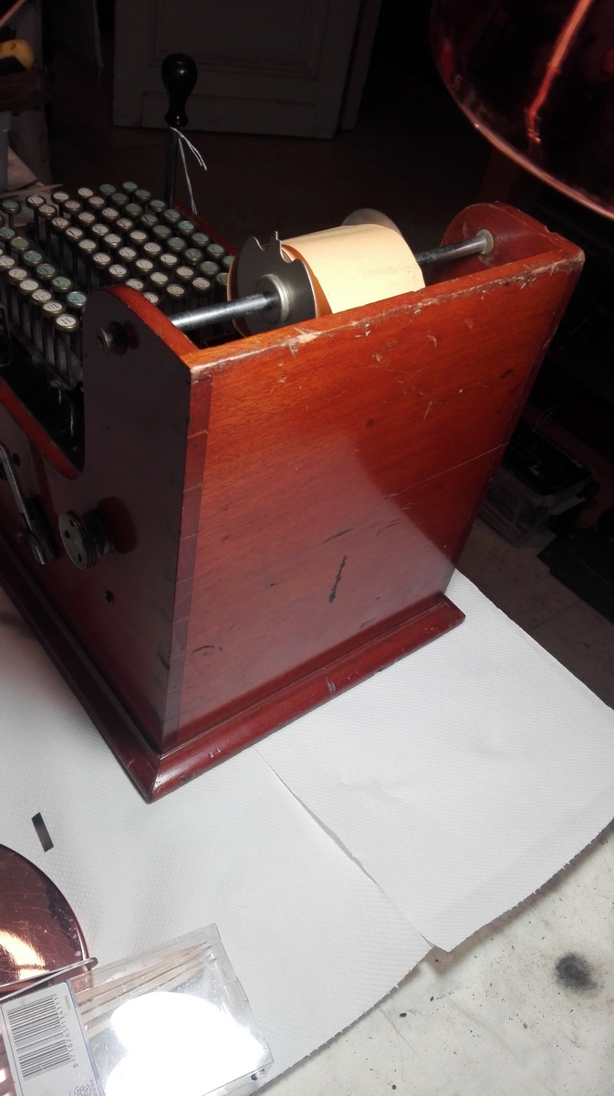
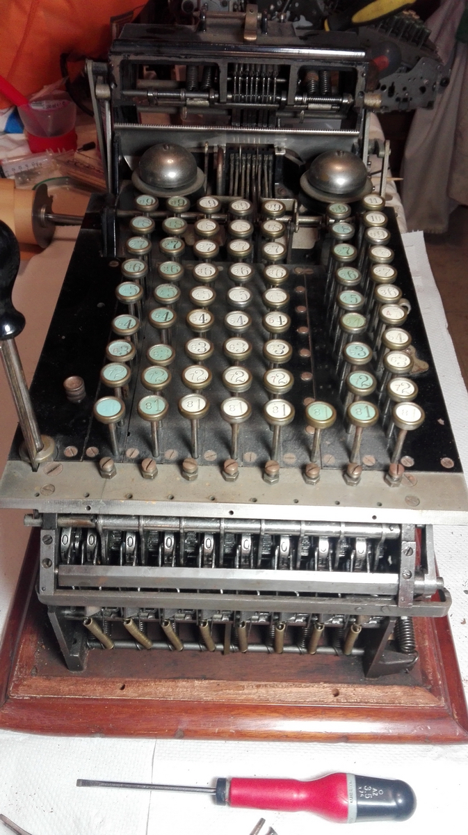
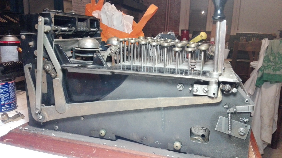
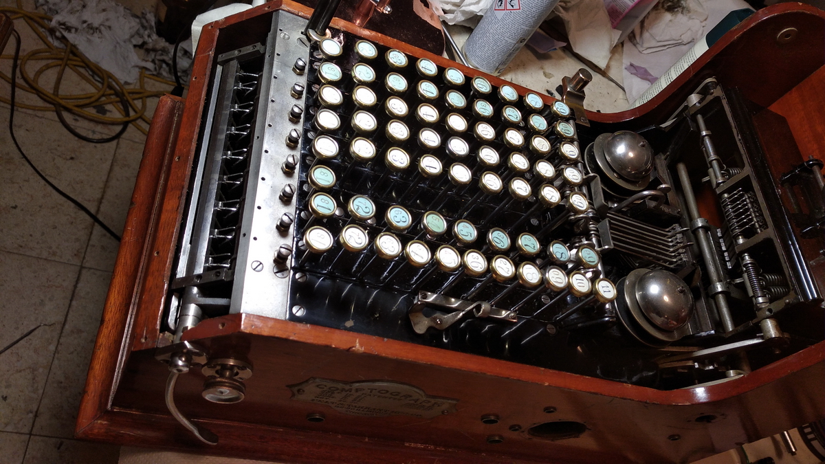
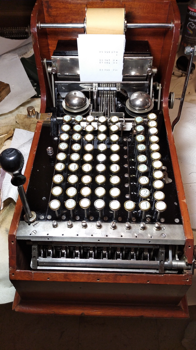
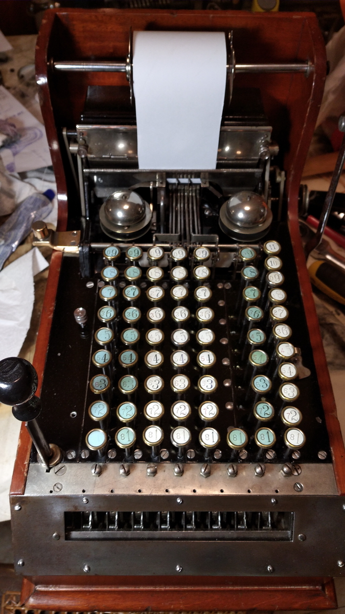
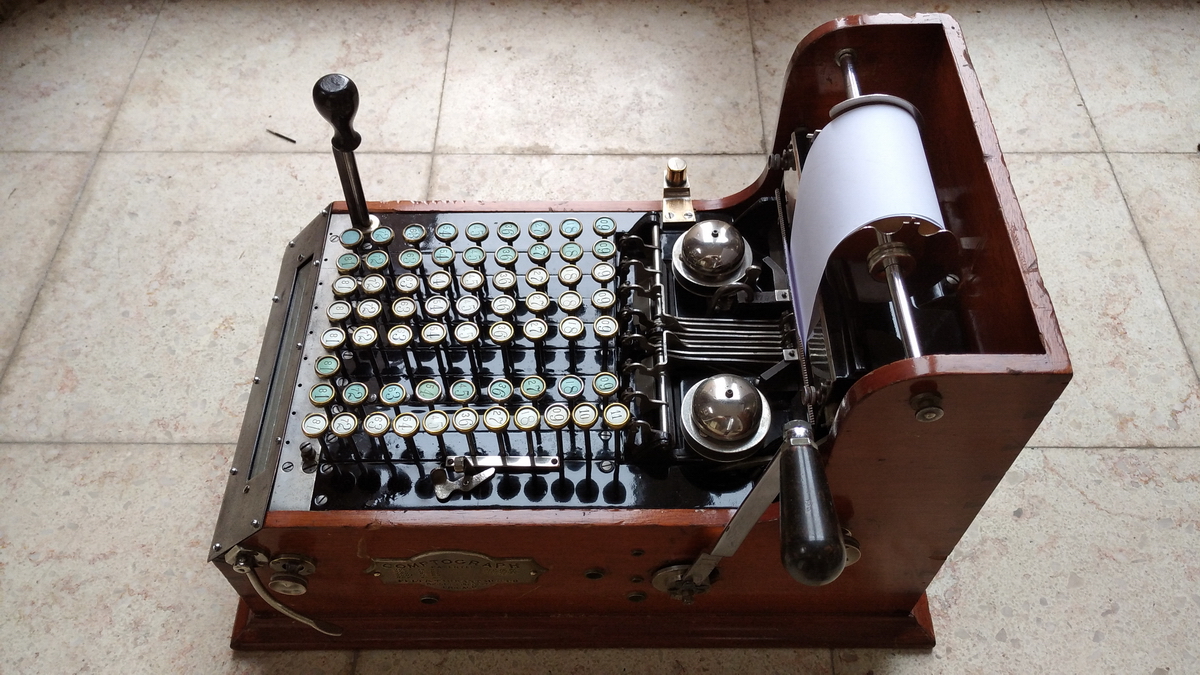
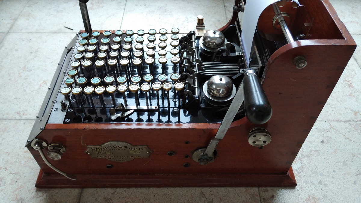
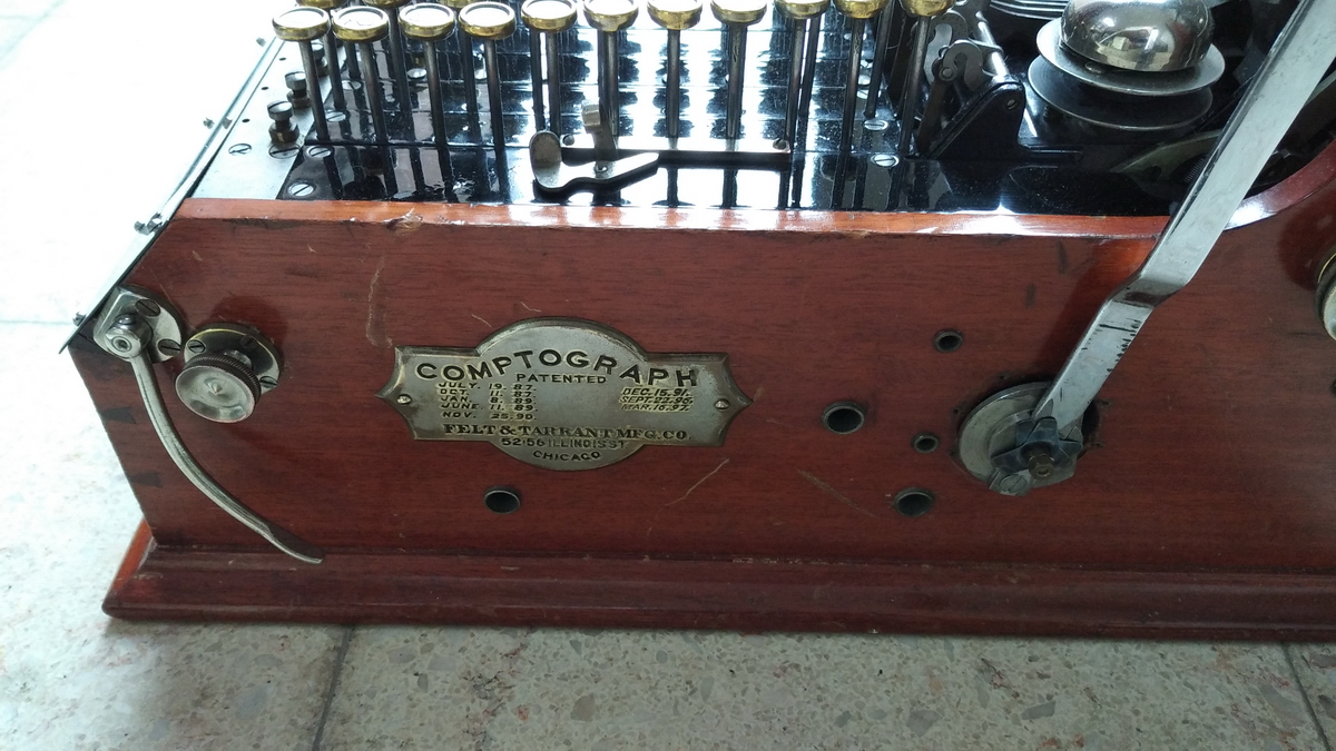
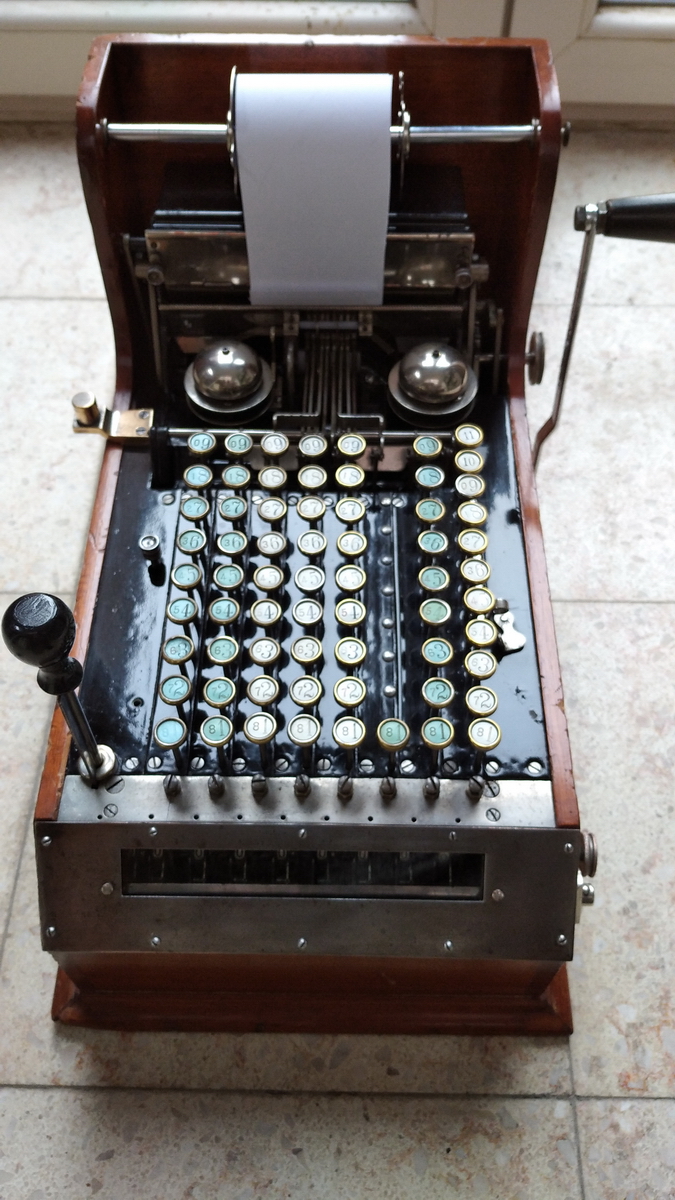
This was a very interesting commission for calcusaur.us - a Comptograph, a printing version of the Comptometer, which was not a great success, because it didn't have the one big advantage of the Comptometer, namely being key-operated and hence fast. This particular one came from the Thomas A. Russo collection, and was bought by the Arithmeum in Bonn, who asked me to have a look at it, for cleaning and restoration.
As far as we could determine when we were looking at it in the Arithmeum, before I accepted the commission, the machine appeared to be basically functional, and was just very stiff, dried out, dusty and dirty.
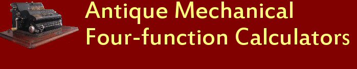
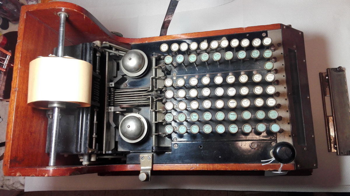
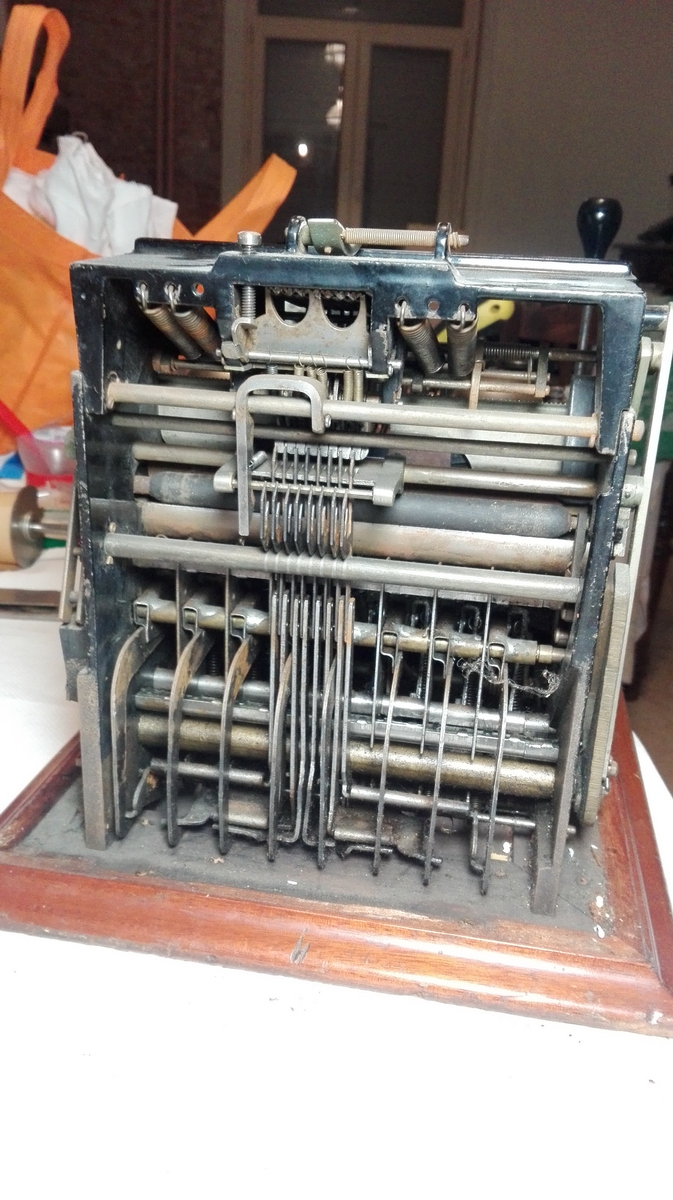
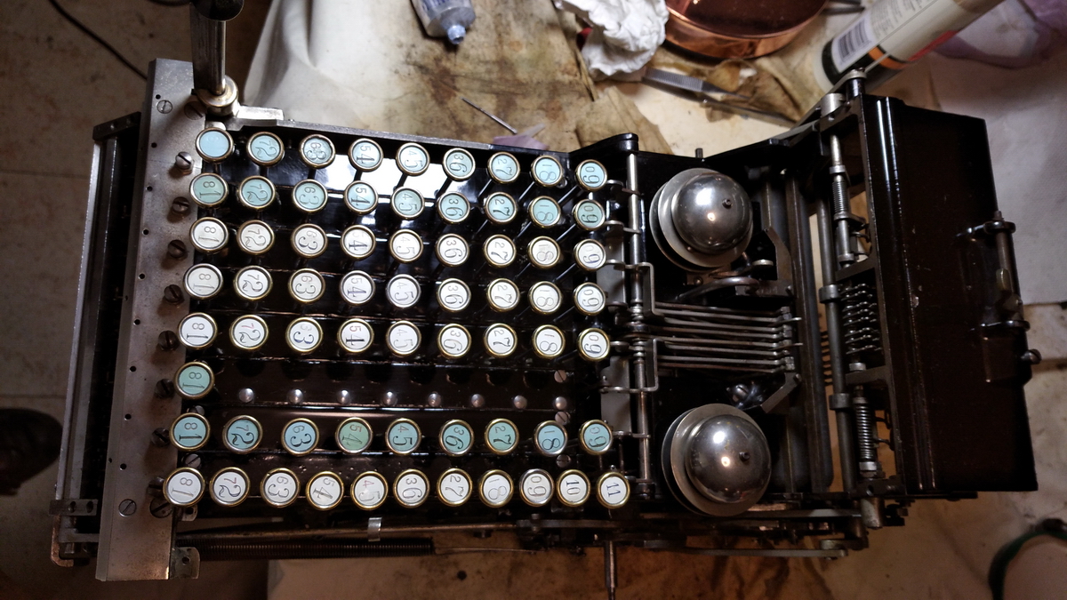
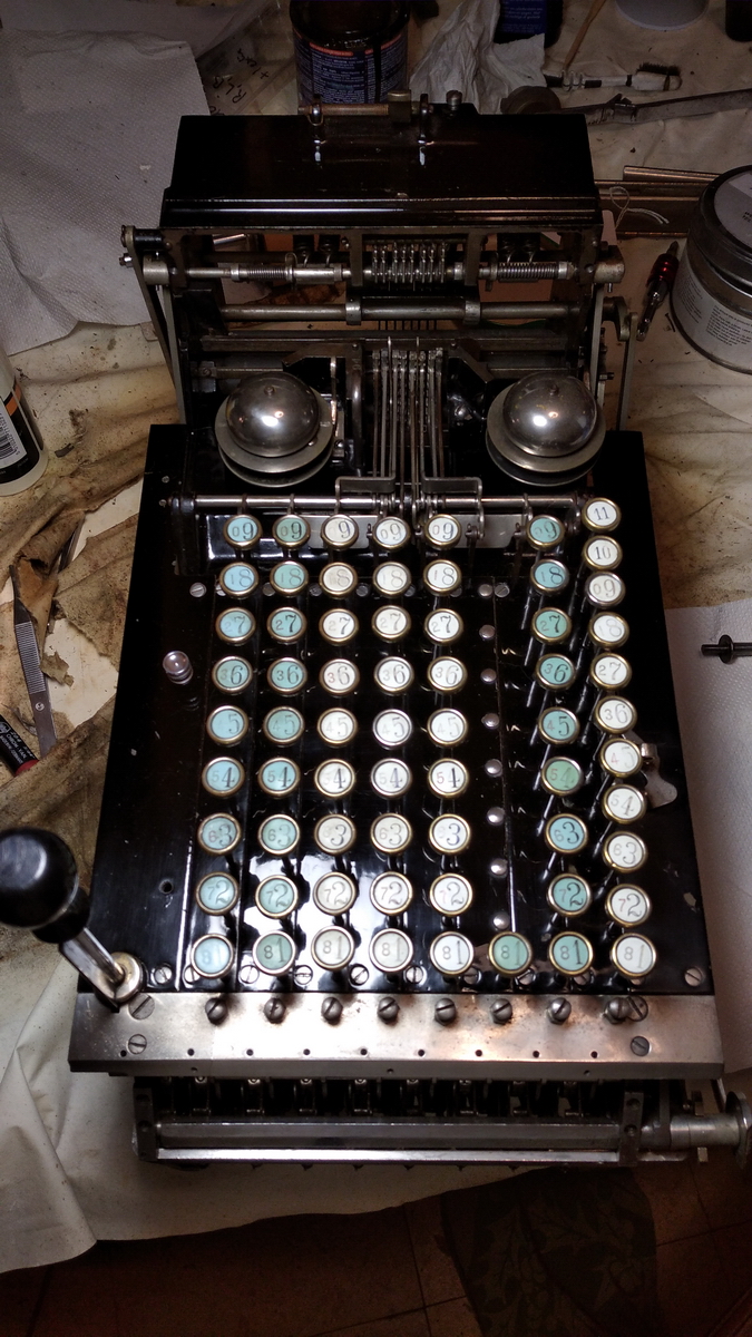
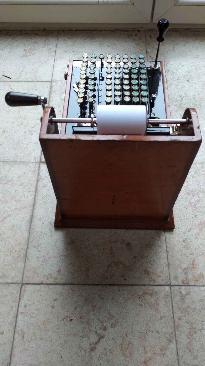
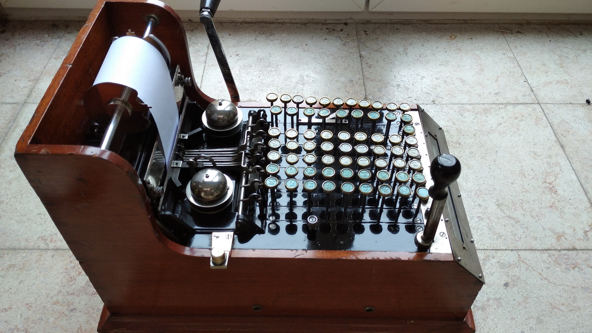
When I arrived home with it, the first thing I did was to make pictures from all sides to document what it looked like bofore starting work on it. I also took the paper guide off.
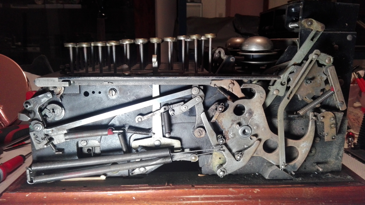
Because everything was so dirty and dusty, I started by brushing the dust out from where I could reach it with a soft brush, and it also became obvious that a large part of the stiffness was due to dried out oil on the pivots for the printing sectors and their operating linkages. The machine would have to come out of the wooden box to remedy that.
Another thing that stood out was the plexiglass cover for the result wheels. That would have to go.
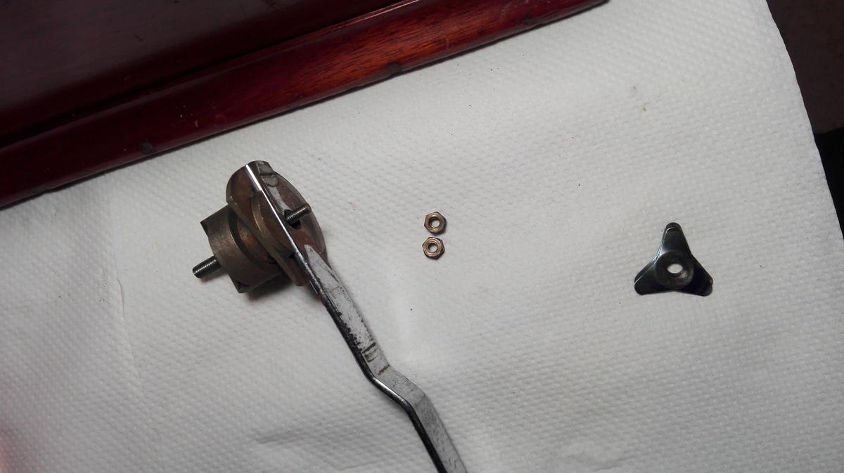
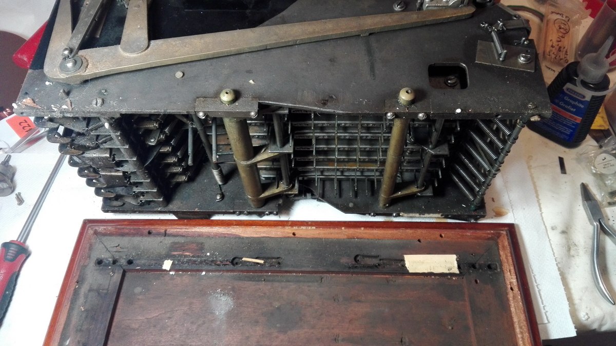
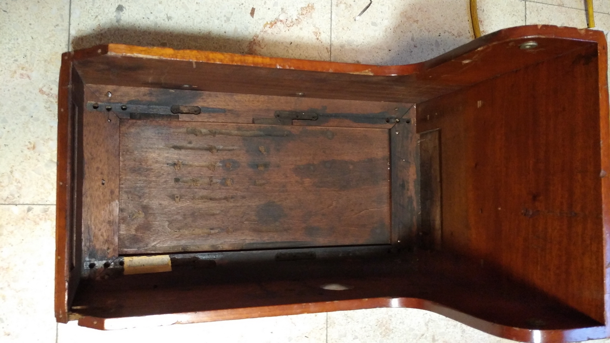
In order for the machine to come out of the wooden box, the clearing for the result register would have to be removed, as the wooden box is an integral part of keeping it in place. It's a quite contorted assembly, that only came out after a bit of a fight. Also the main operating handle had to come off, as well as the paper advance wheel.
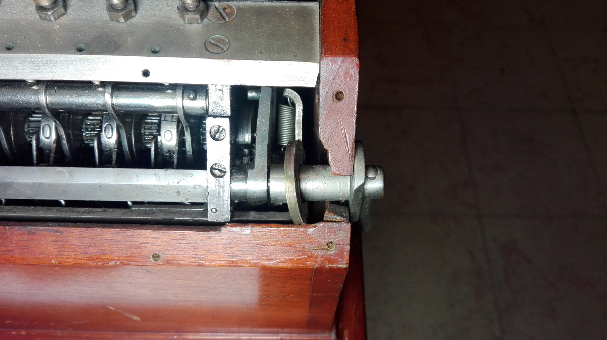
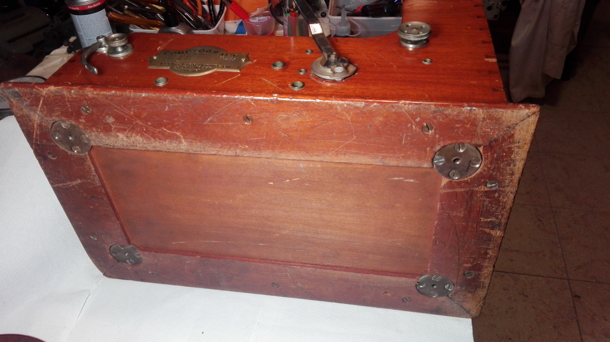
The machine can be mounted on feet, which in turn are screwed into round metal plates at the corners of the wooden box. Part of the screws are wood screws that hold the disc in place, but part are machine screws which keep the machine to the bottom of the wooden box. I opted to undo all the screws that hold the upright sides of the box to the bottom plate, and then slid the sides up and off the machine.
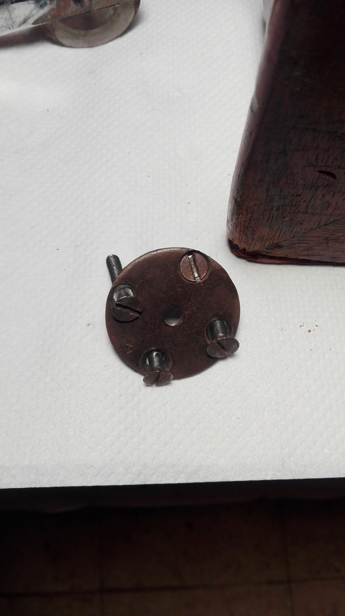
That only damaged a tiny bit of varnish on the front endge of the box, where the upright front meets the bottom plate.
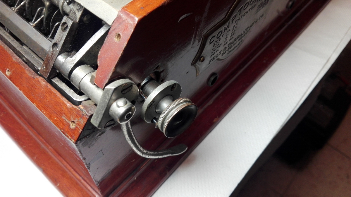
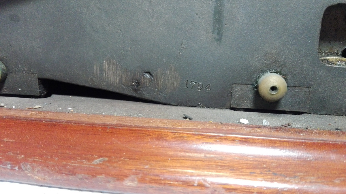
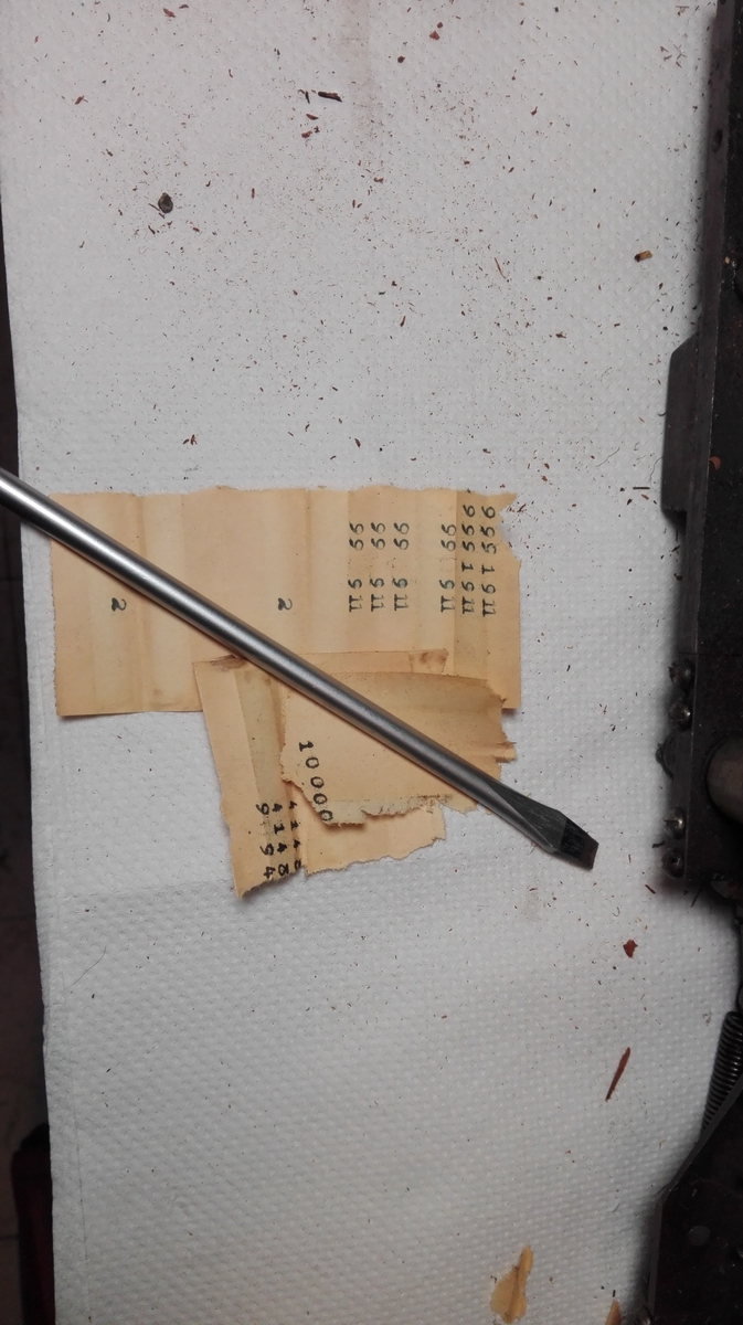
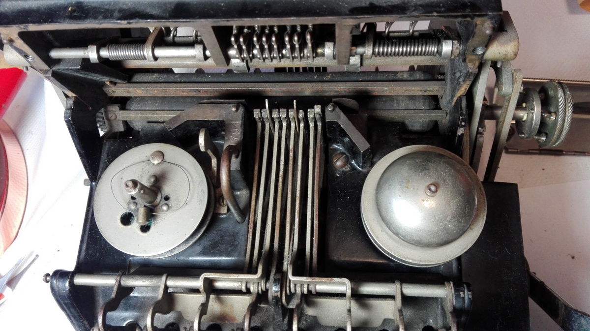
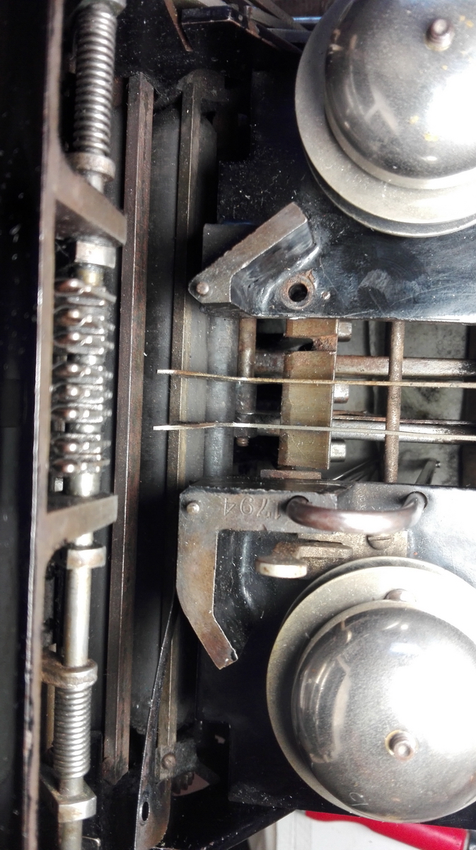
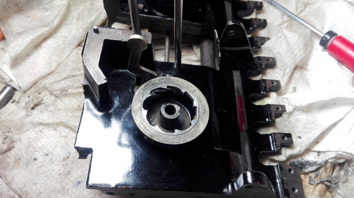
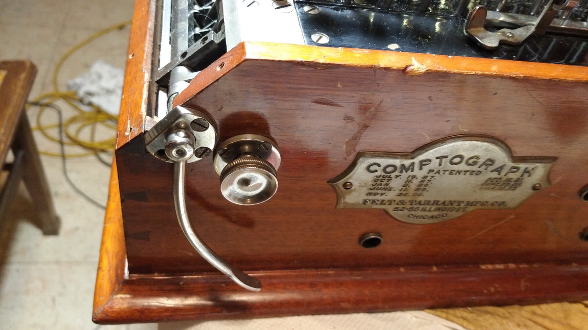
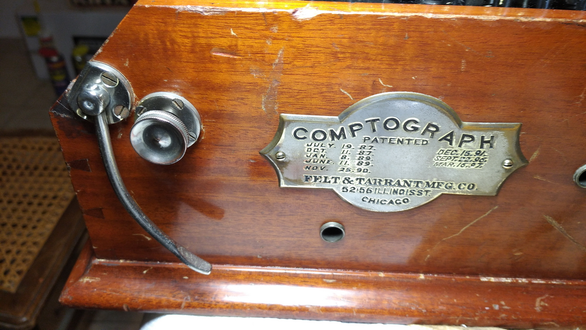
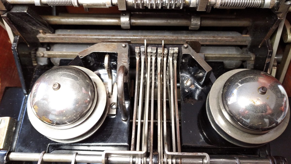
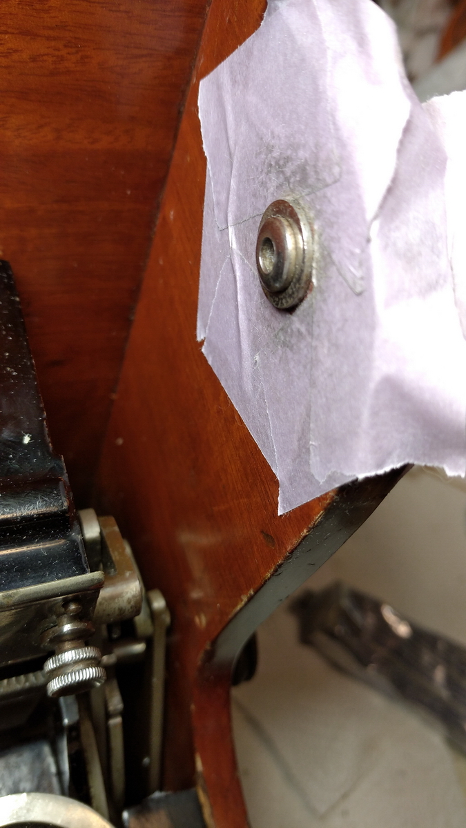
The serial number can be found here - 1794.
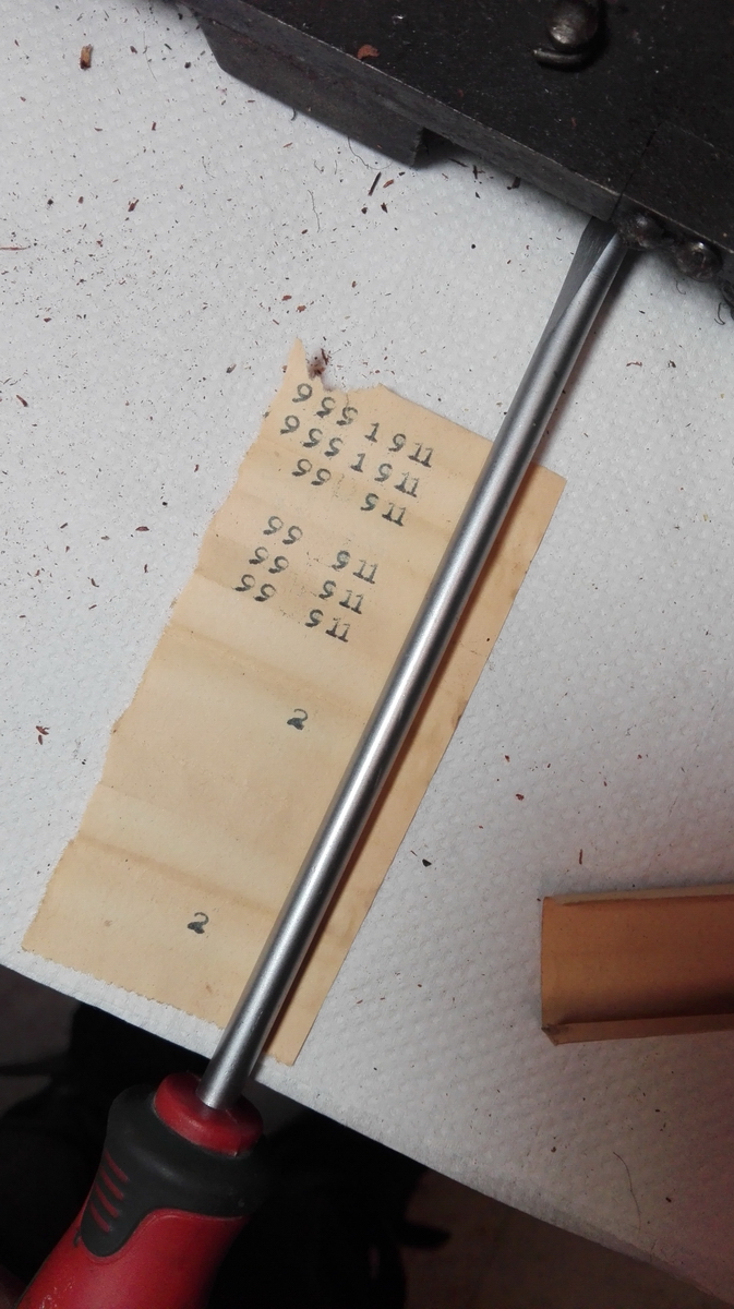
Then the machine could be unscrewed from the bottom plate and cleaning could start in earnest. I found a sample of the printing of the machine as a shim under the front right corner.

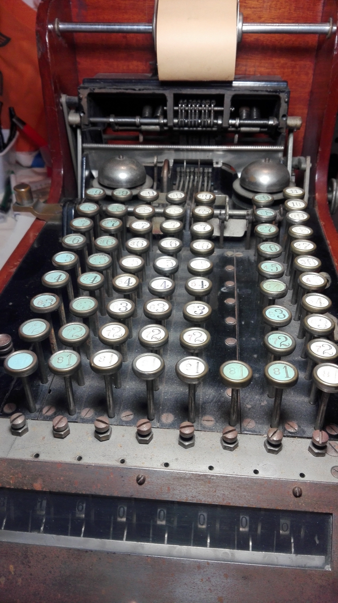
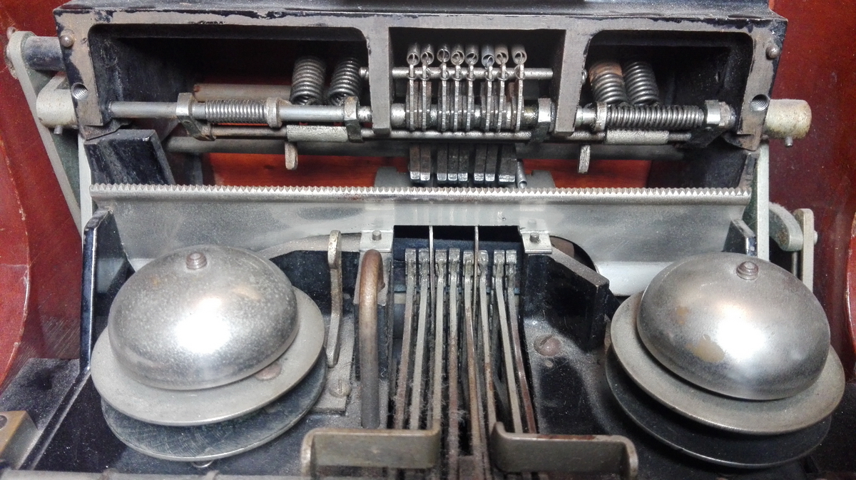
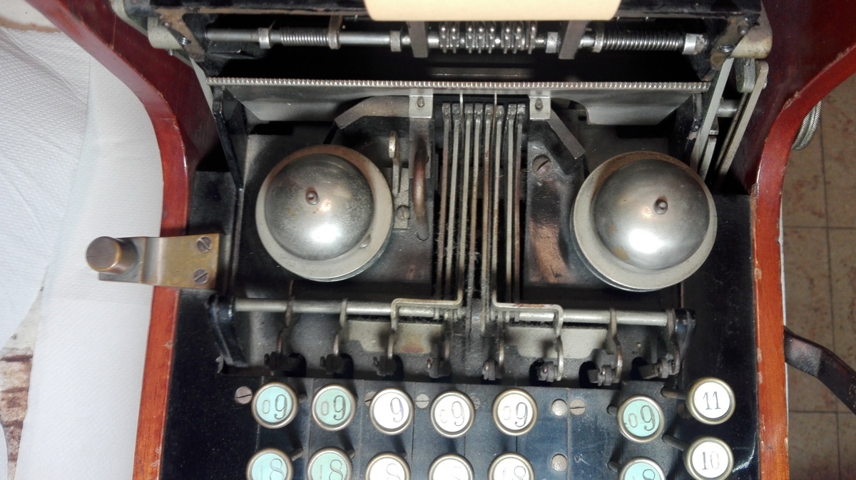
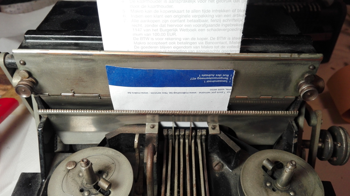
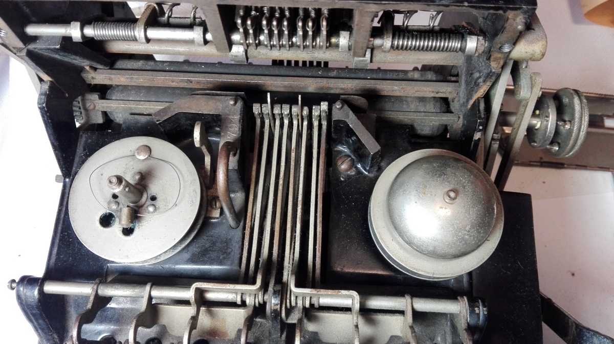
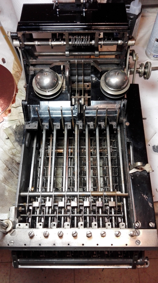
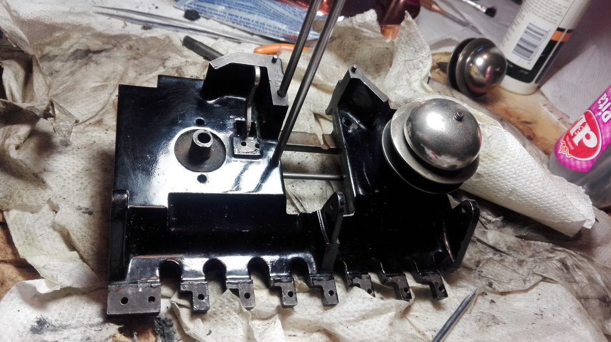
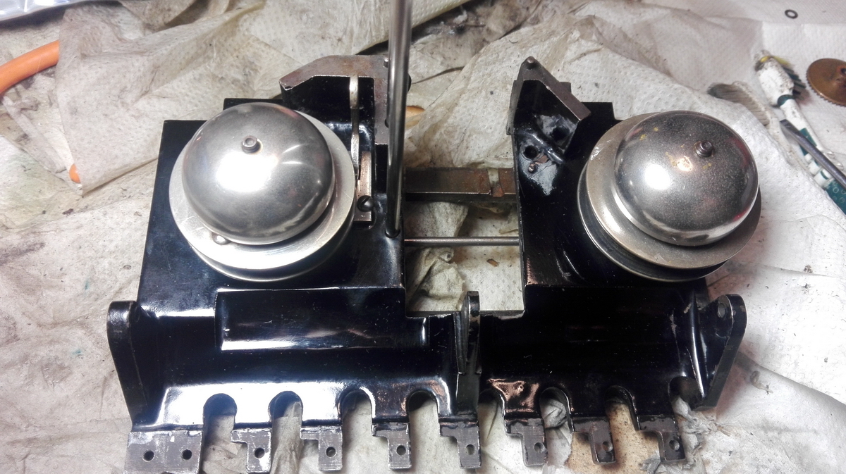
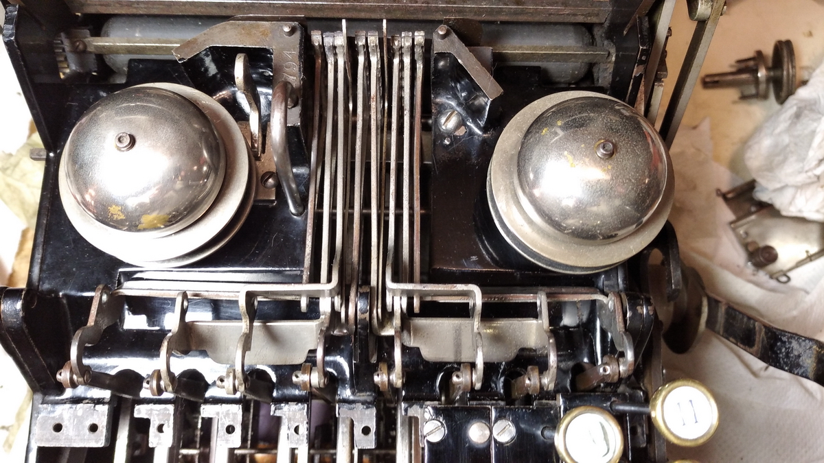
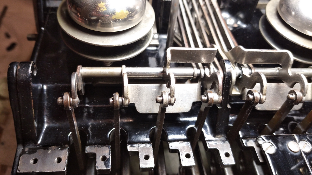
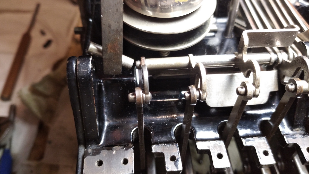
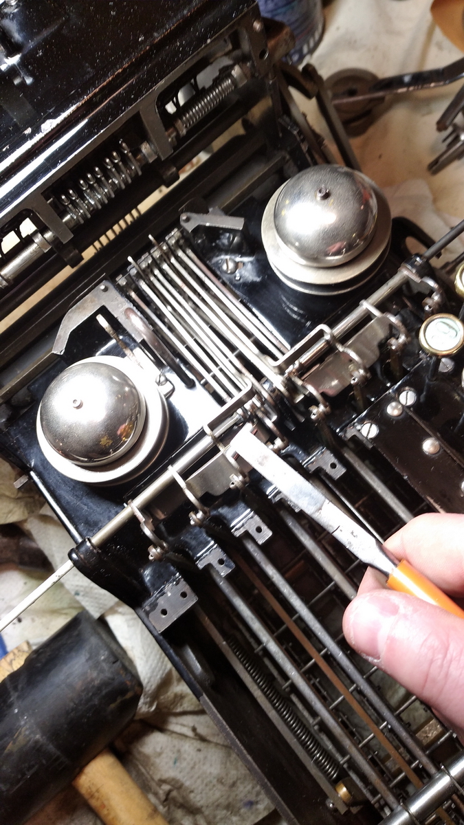
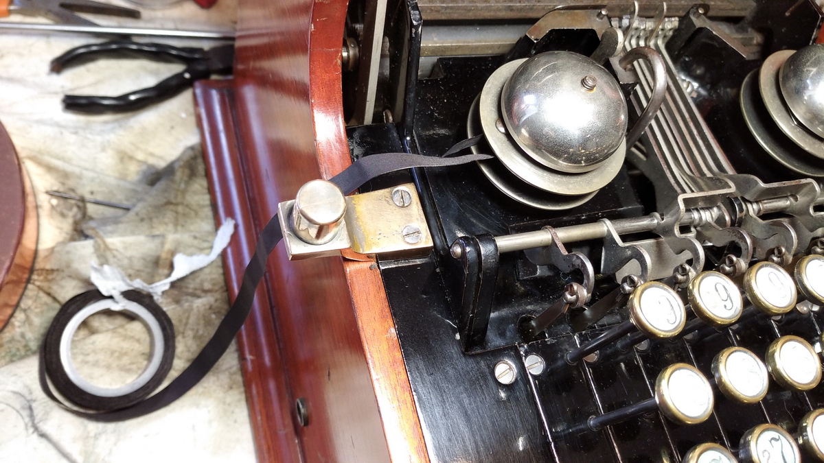
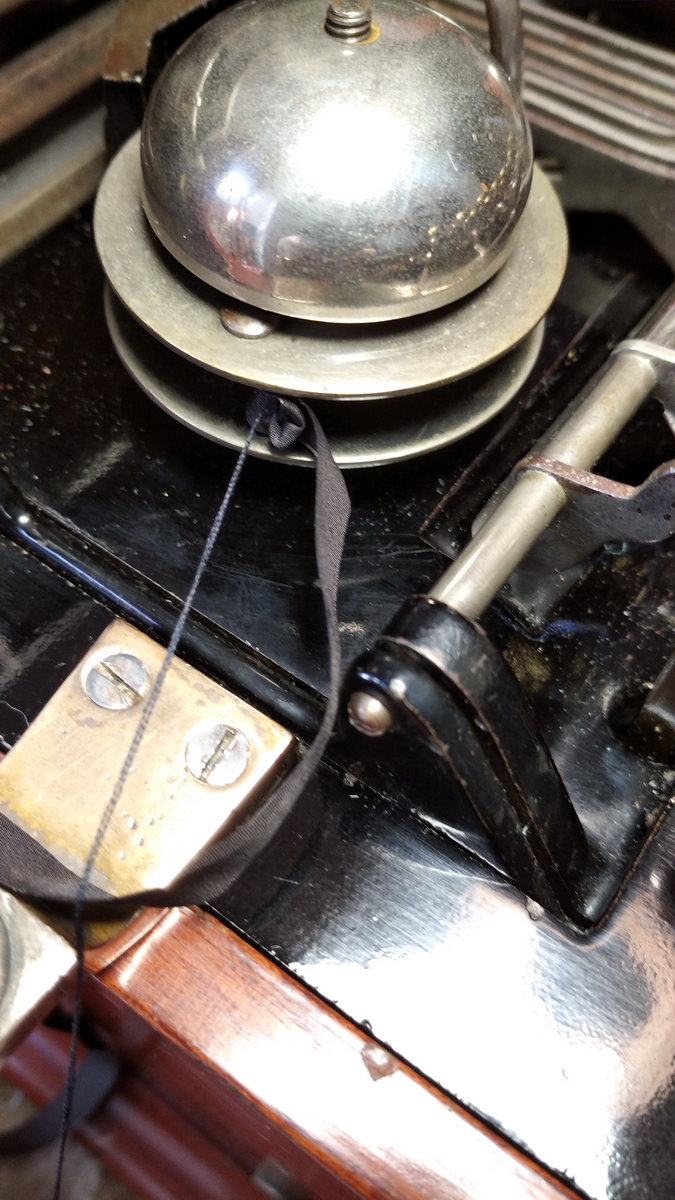
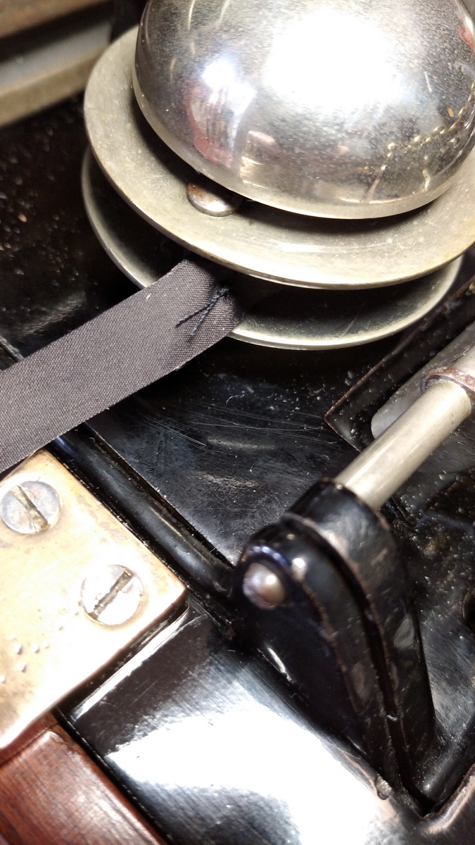
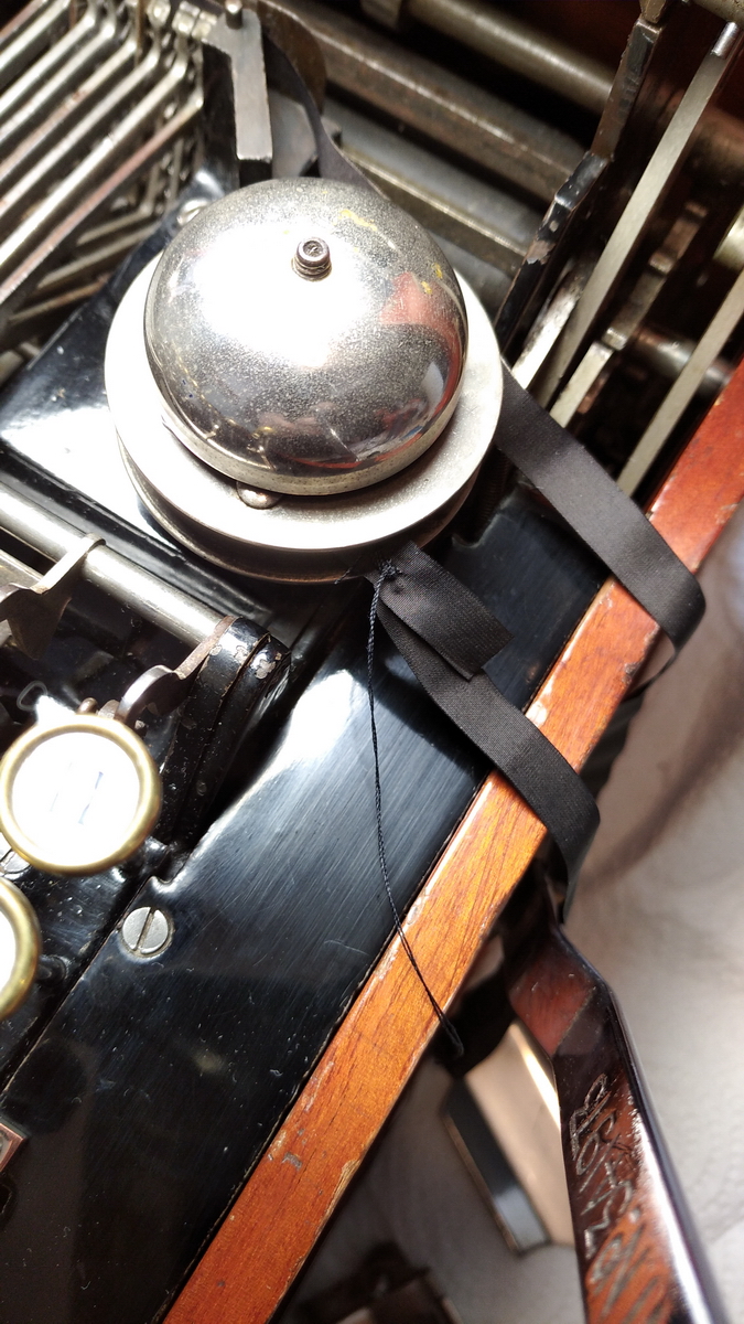
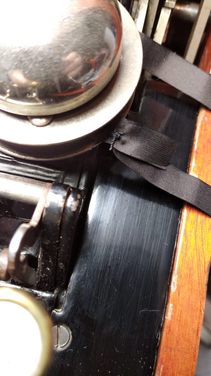
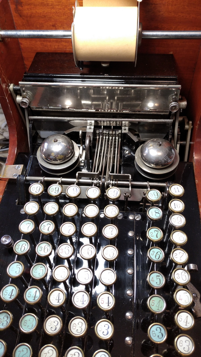
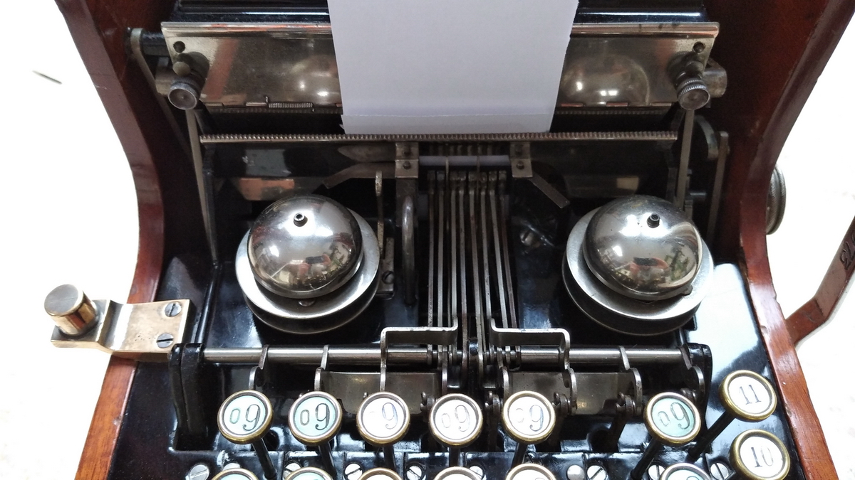
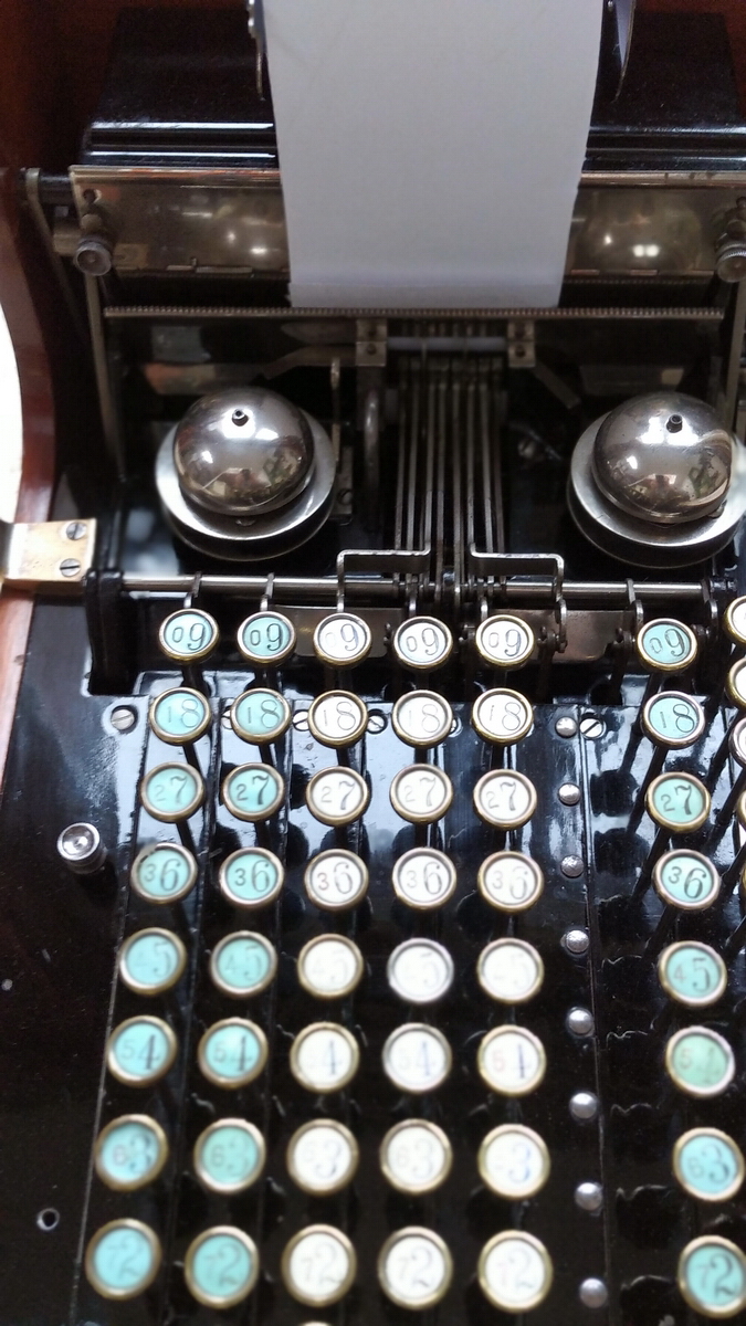
I reassembled the paper table to document how paper would go through the machine, and then disassembled the bells to reveal the mechanism for notifying the user that the ribbon should be reversed. It is beautiful, I will show more of it later.
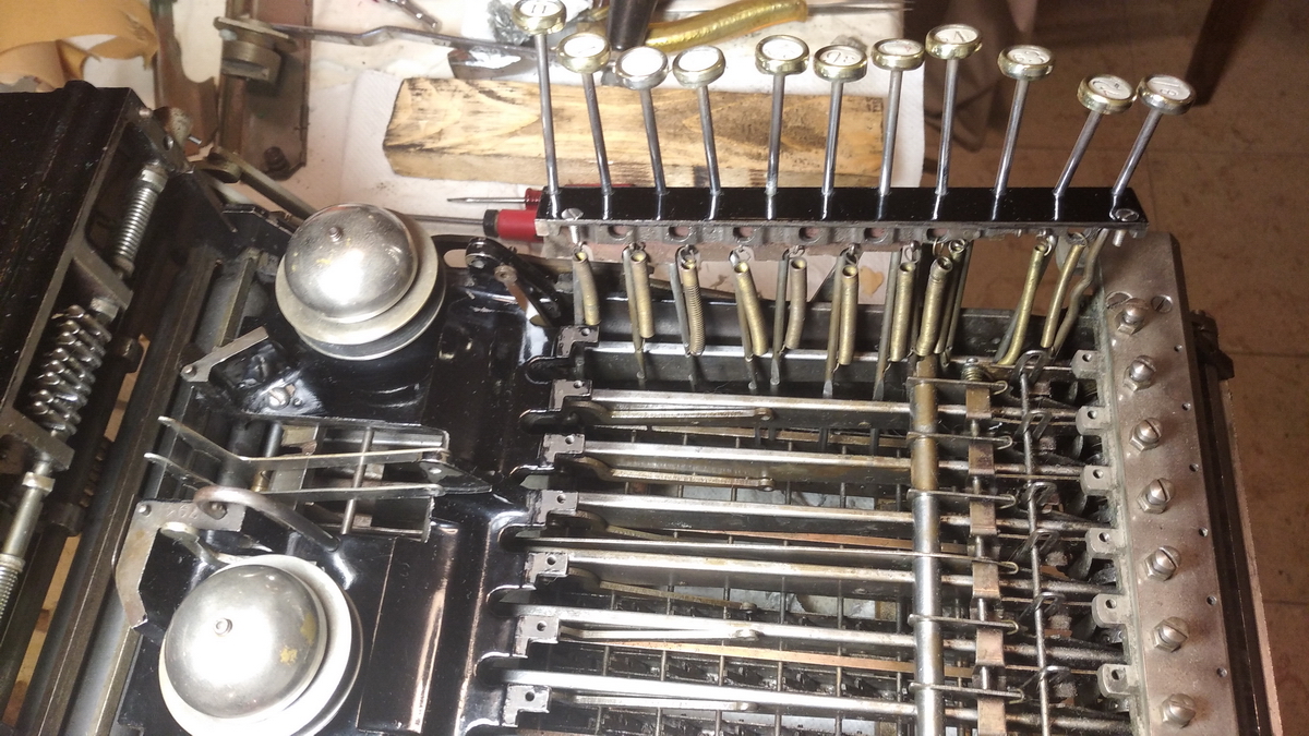
At this point also the old dried-out ribbon was taken off the machine. Then, in order to get at the linkages for the printing sectors, the keyboard needed to be disassembled.
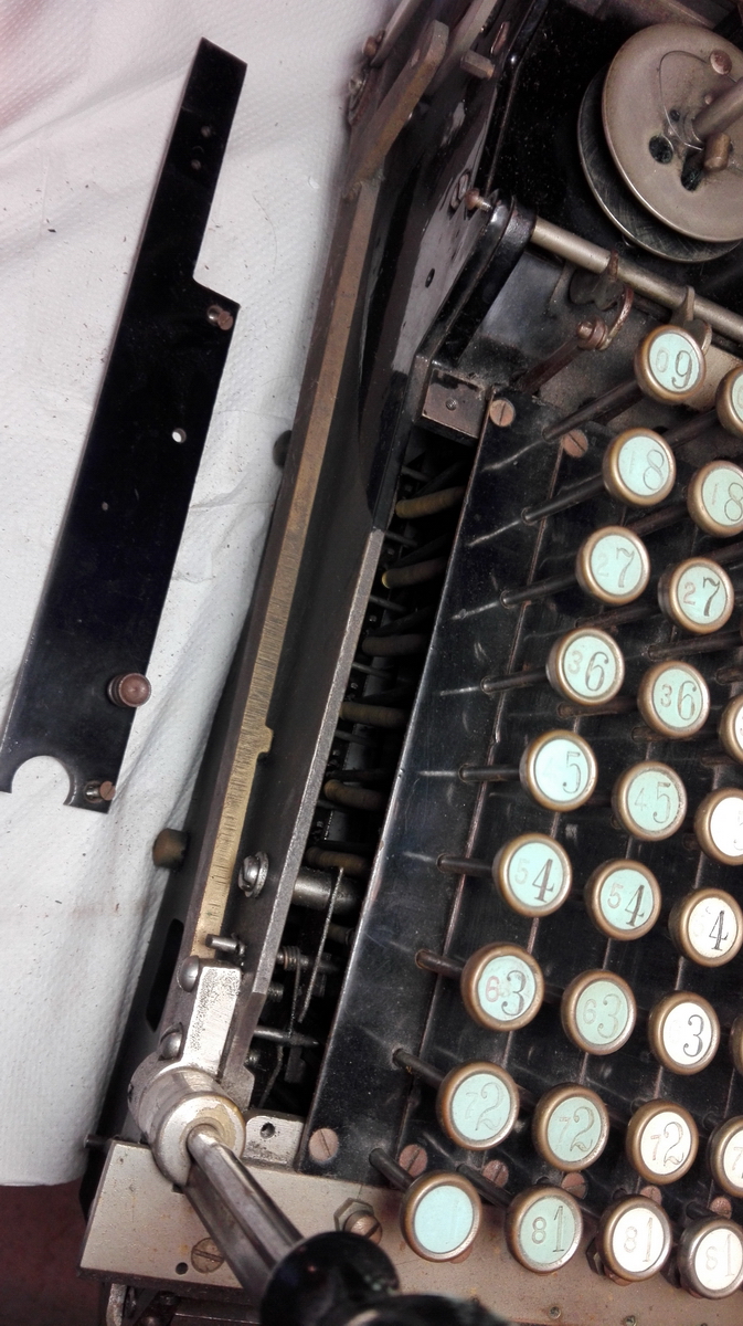
With some trepidation, I undid the screws and lifted out the leftmost keyboard row. I then verified that I could also put it back (you need to push the keyboard clearing in order to do so, and then it is a bit fiddly, but not a big problem). After trying that to my satisfaction and verification that it was still operational, I disassembled all of the keyboard. The insides of the machine were just as grotty as the outside.
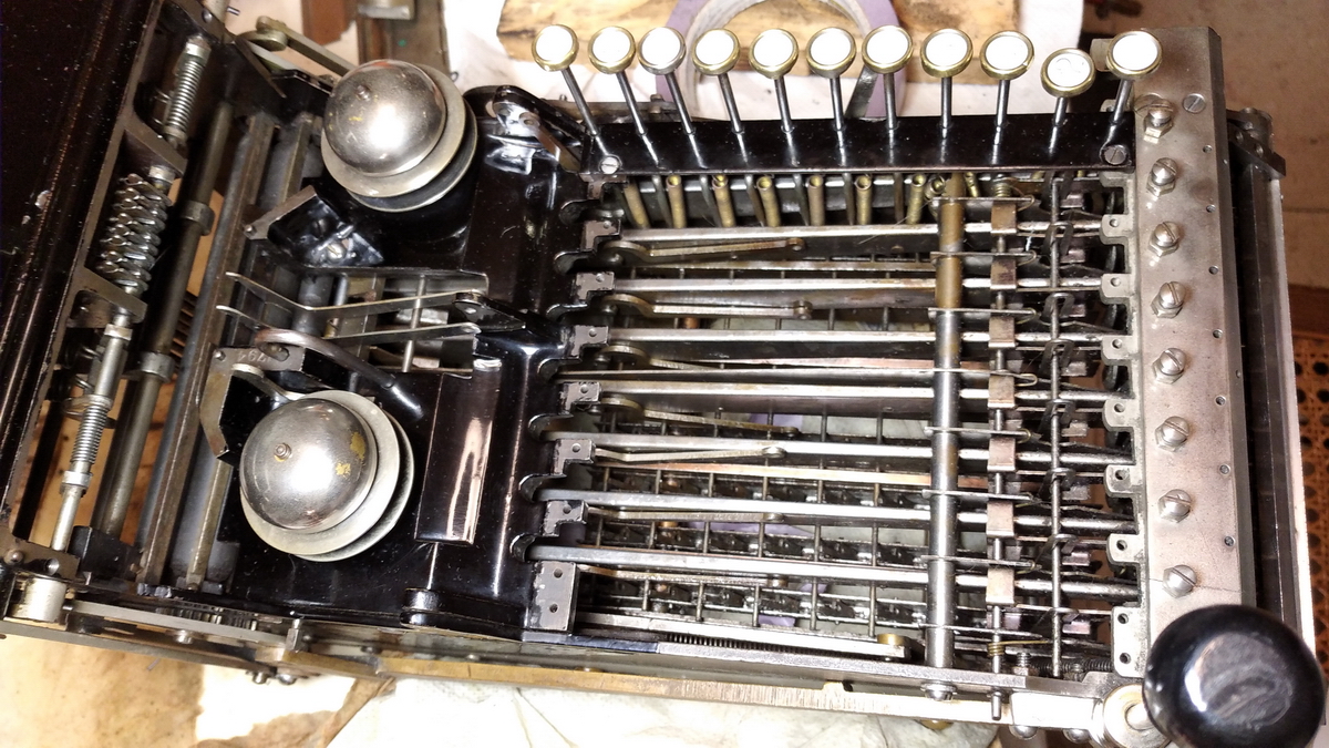
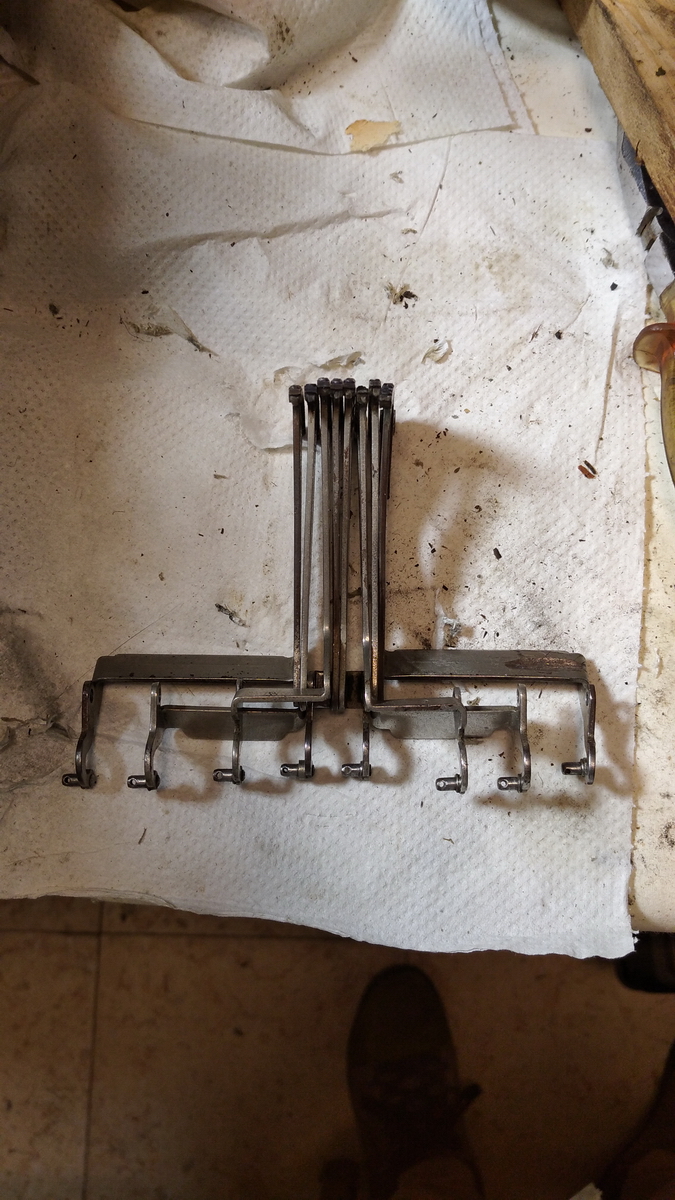
The next thing to start disassembling were the printing sectors and their linkages. This could be done by removing the two screws on the through-axle, and carefully tapping it out, taking out all the spacers in sequence as they came out. The linkages to the keyboard as fixed with small split-pins, which can easily be removed, and the linkages disconnected. The order in which the segments go onto the axle together with all the spacers and other elements were obviously carefully documented. More caked dust became immediately obvious.
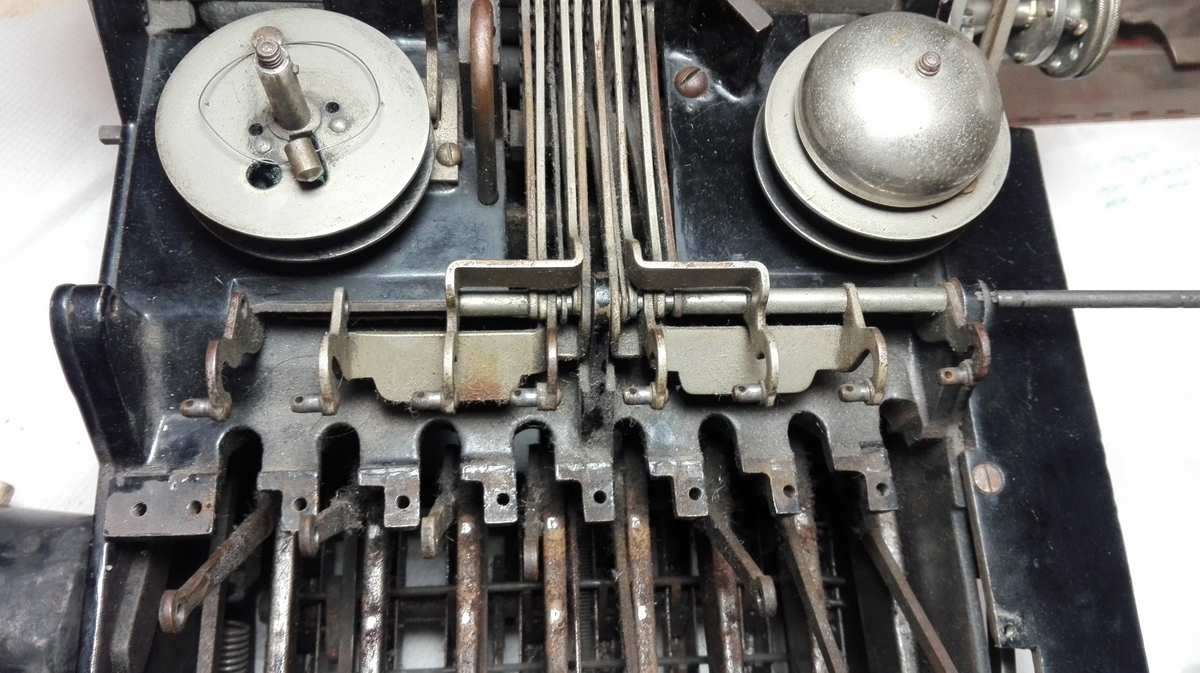
At this point, most of the keyboard linkages could be cleaned, but the one thing I could not get at was the switching lever for the ribbon direction and its cover, because the ribbon spool was in the way. The rest of the insides of the machine are already quite clean now.
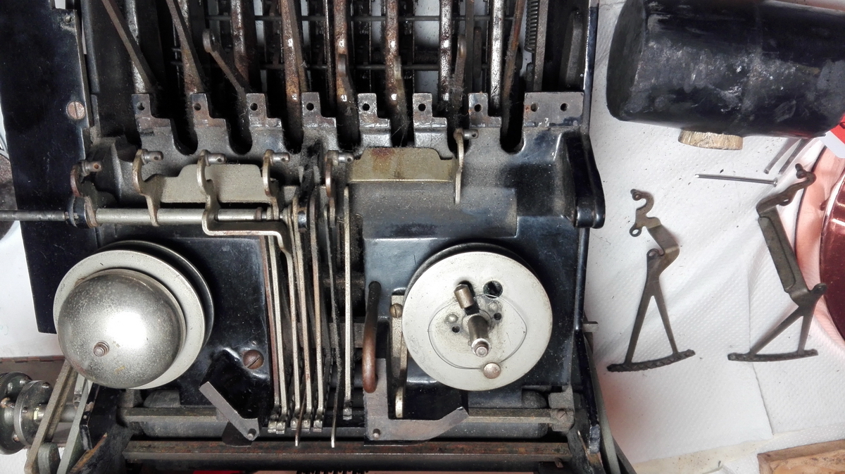
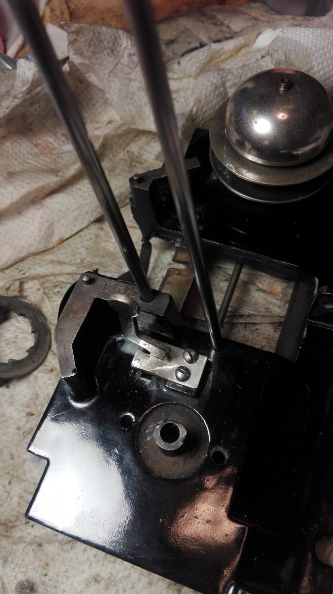
This then led to an excursion involving the removal of the plate with the ribbon spools, which would also alow better access to the inside of the machine for cleaning. However, it is meant to be assembled before all the linkages on the right side of the machine go together, and I was not looking forward to disassemble all of that. So instead I tried my best to get at the one screw hidden behind some of the levers, and succeeded in getting it loose.
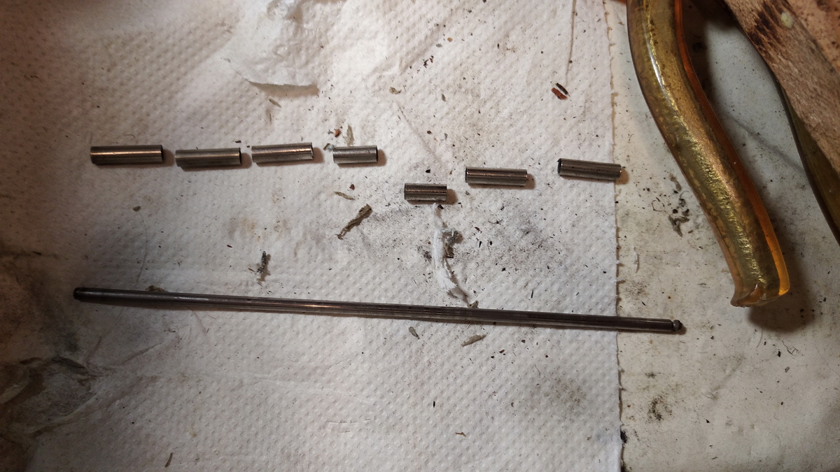
That meant the top plate was now loose, but the guides for the printing sectors precluded it from being removed by moving it straight up, and the axle turning the ribbon spools sticking out the right side prevented it from coming forward. So that meant that one of those had to go, and I chose the segment guides as the lesser evil. They are mounted on a rod with some spacers and a nut at the end, which I could just get to with pincers and long-nose pliers.
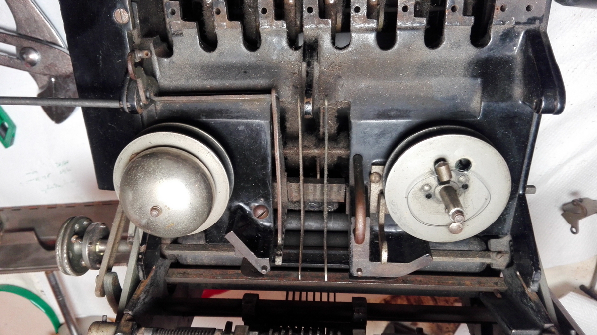
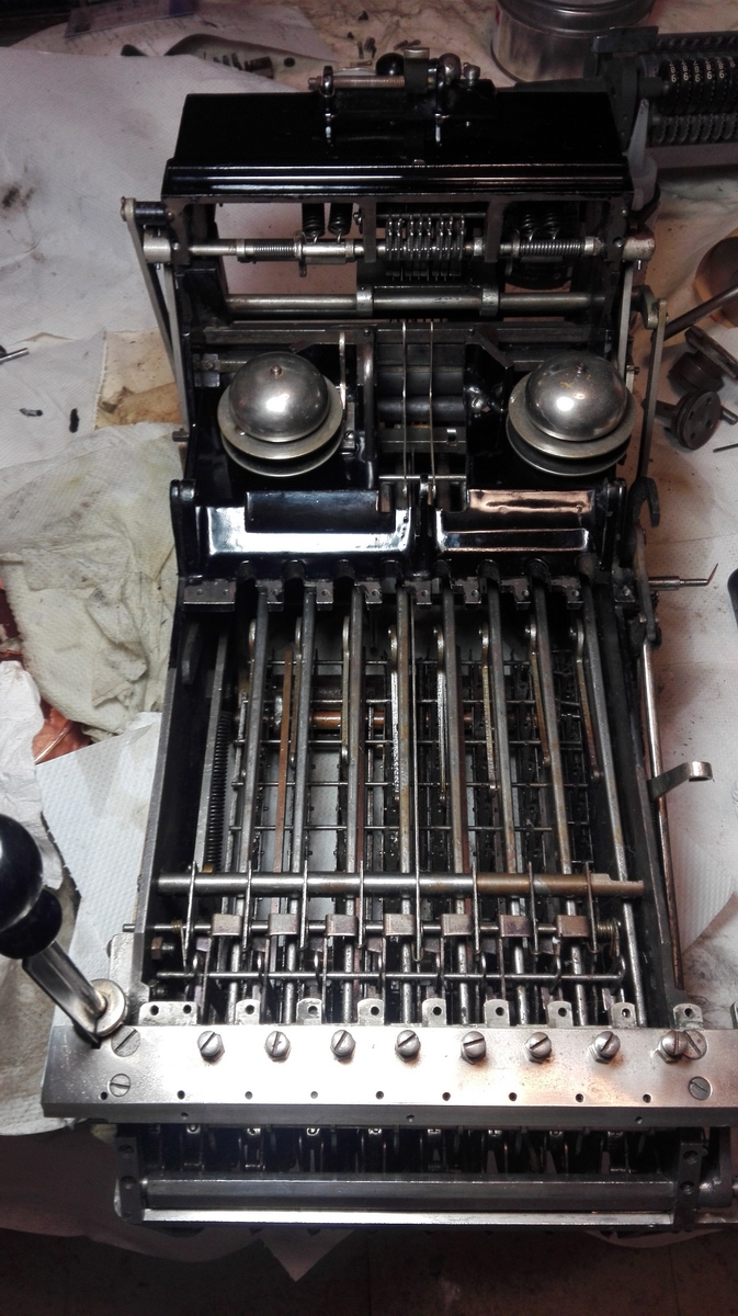
With everything out of the way, this allowed proper cleaning of the machine body, as well as of the ribbon spool mechanism.
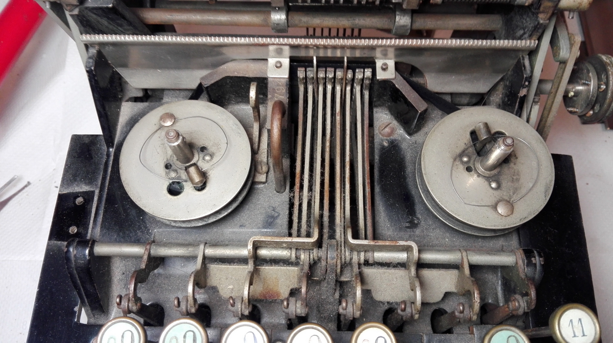
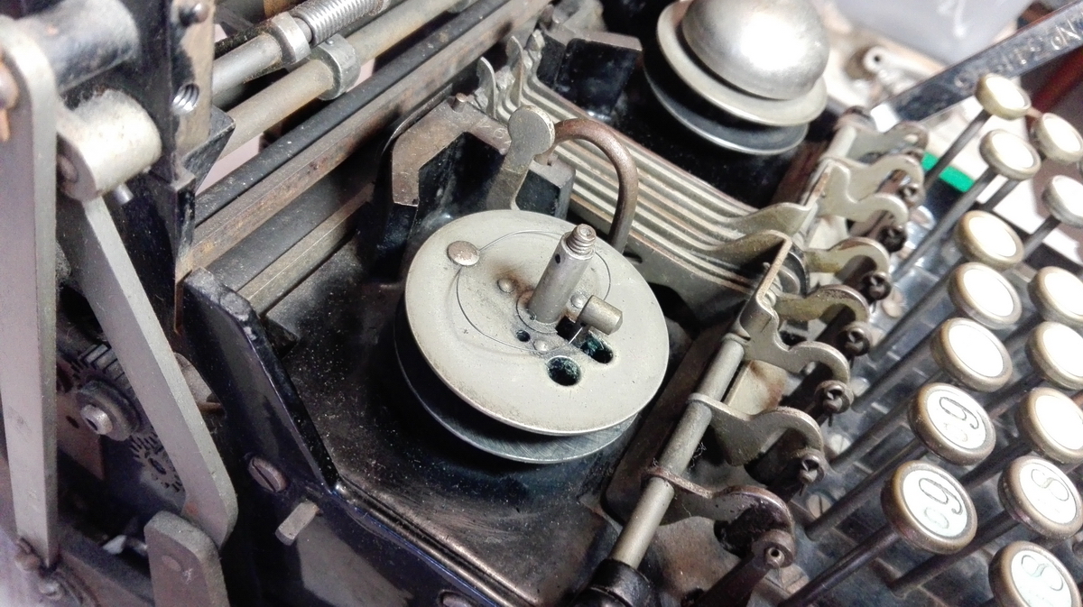
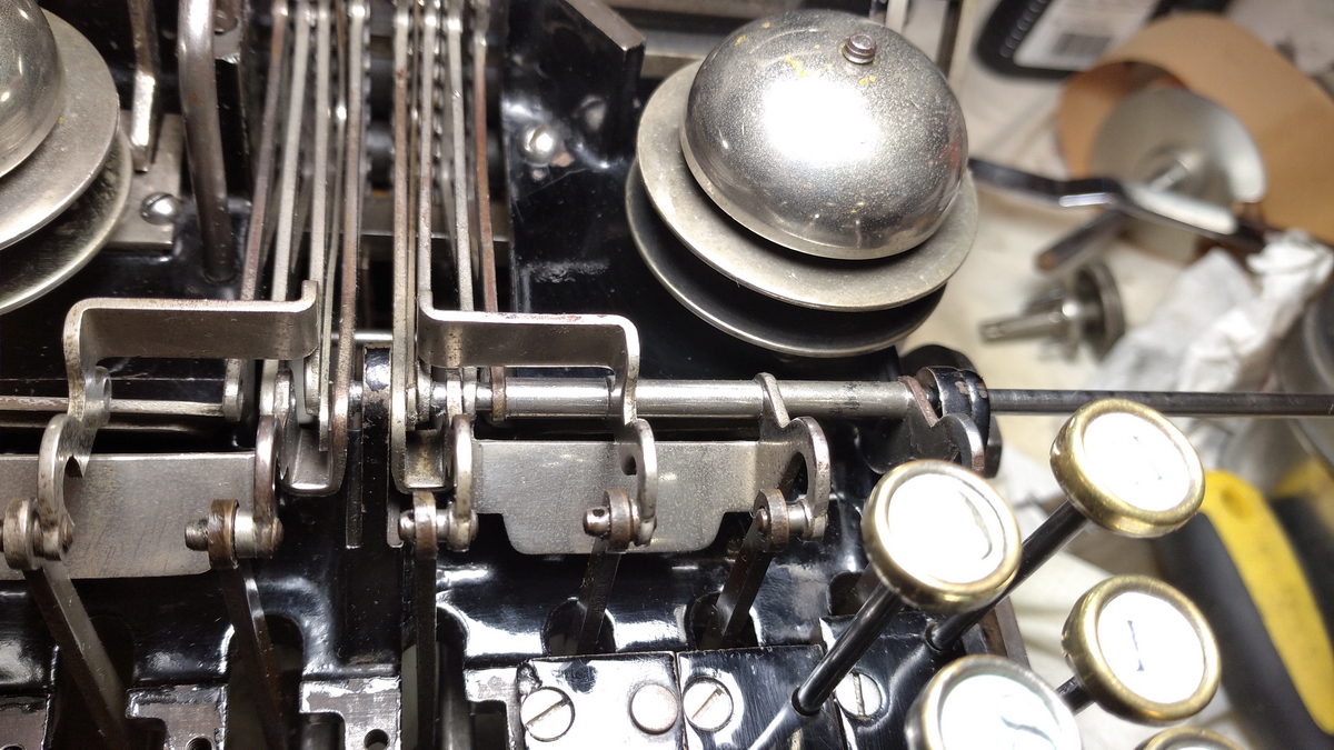
I had to disassemble one of the spools, which required taking the bevel gear that was pinned to the axle off.
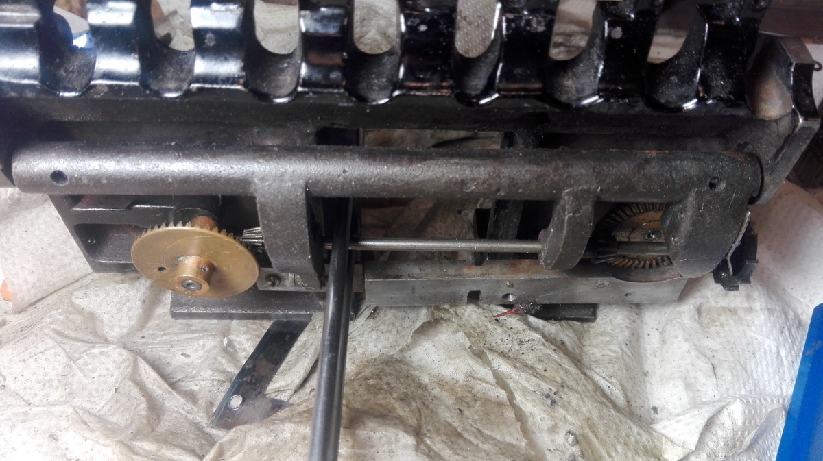
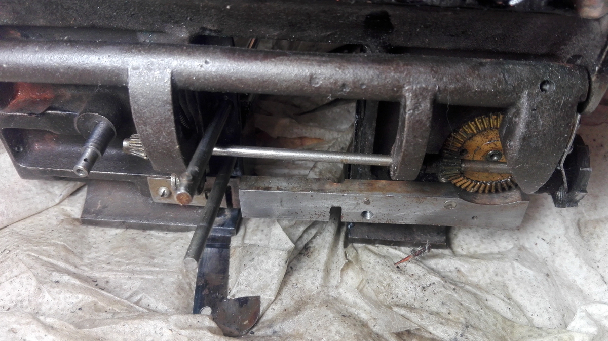
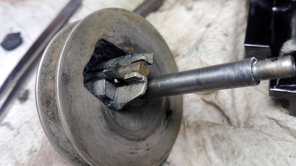
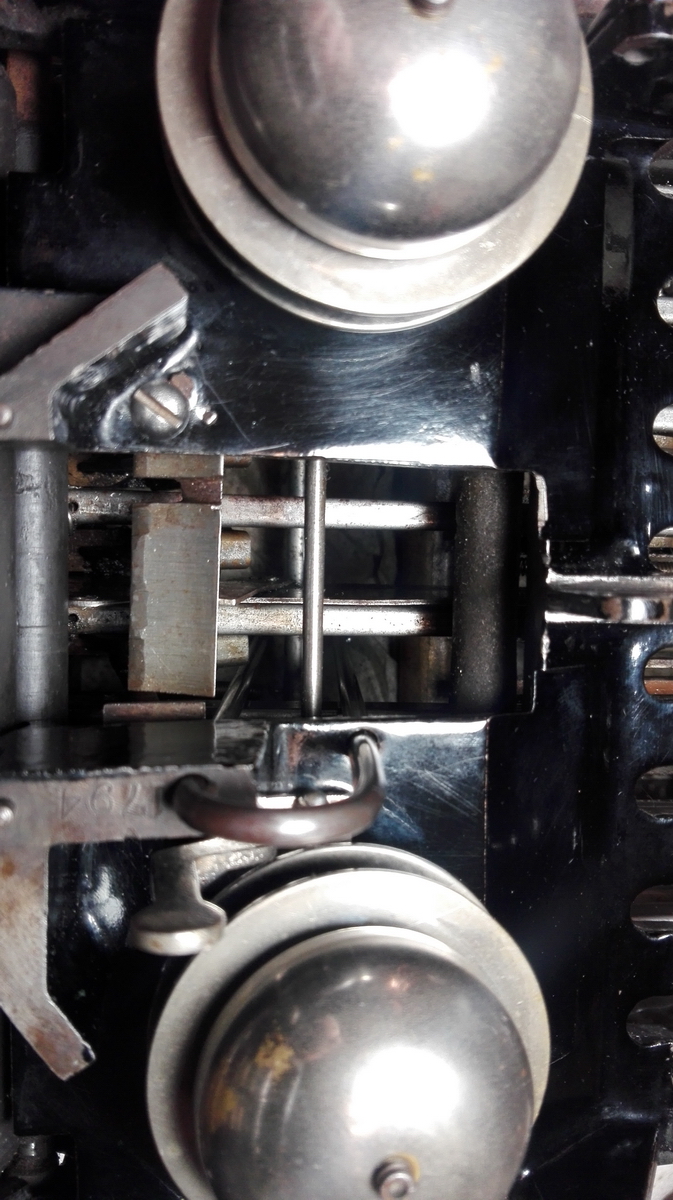
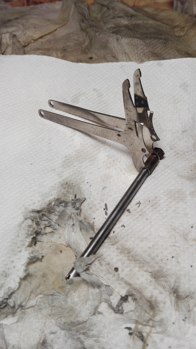
Luckily this turned out to be quite feasible, it wasn't a tapered pin and came out without much of a fight. This also allows us to see the details of the hilarious end-of-ribbon mechanism. There is an internal gear mounted on springs, that the axle for the ribbon spool moves through. As the spool rotates, there is a catch on the side that trips over all of the teeth, and is connected to a shaft that comes up through a slot in the centre of the ribbon spool, with the hammer for the bell mounted on top of that. If a ribbon is wound onto the spool, the shaft is pressed inside the centre of the spool, and if the catch runs over the internal teeth, it pulls the shaft further inside and releases it on every tooth. However, the shaft and bell hammer are prevented from reaching the bell, by the presence of the tightly would ribbon around the centre of the ribbon spool. However, as soon as the ribbon reaches the end of its travel, it no longer restrains the hammer, and on every 1/8th rotation of the spool, the bell will sound, alerting the operator to the fact that the ribbon reverse lever needs to be switched to the other setting to run the ribbon back onto the other spool.
Removing the spool allowed to clean up the ribbon selection lever. After mounting everything back onto the ribbon spool plate, it was polished up, and mounted back inside the machine.
Then the printing sement guides and their axle and spacers had to be put back inside the machine, using pincers, pliers and at some point plasticine to hold the nut in place. It wasn't pretty, but in the end it worked, and no plastcine was left inside the machine...
I then polished up the nickeled parts at the front of the machine, and called it a day.
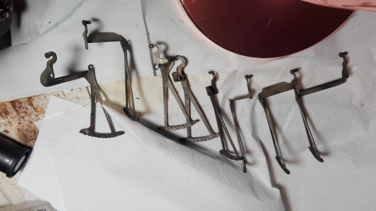
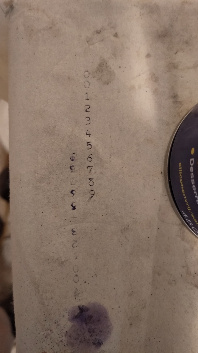
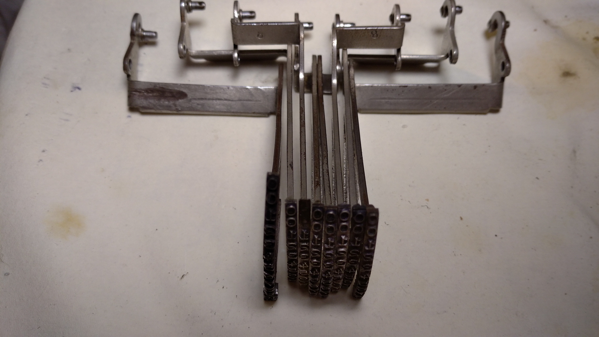
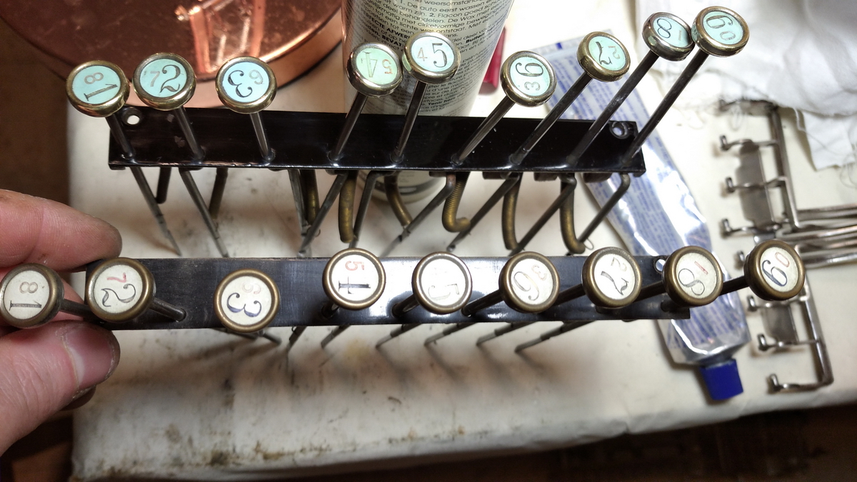
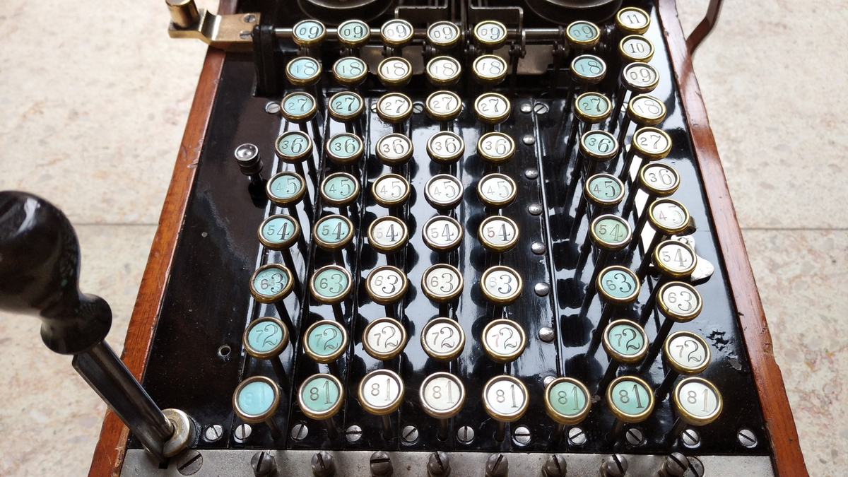
The next points of attention were the disassembled keyboard and the typebars. Cleaning these allowed me to get a nice impression (pun intended) of what the type looks like. Notice the double 0, about which more later.
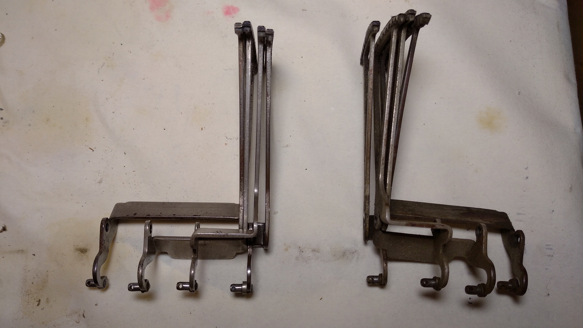
One side is clean, the other isn't ...
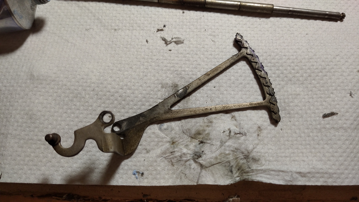
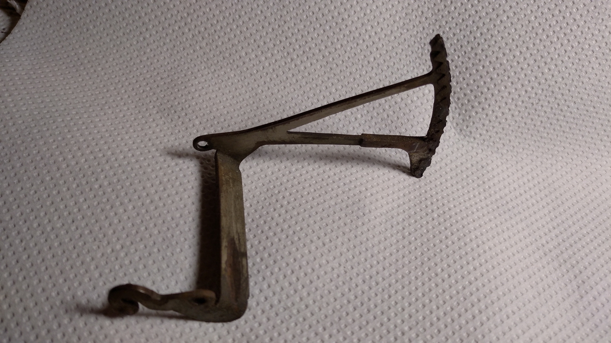
This is the "special" type arm that goes to 11 in the rightmost row.
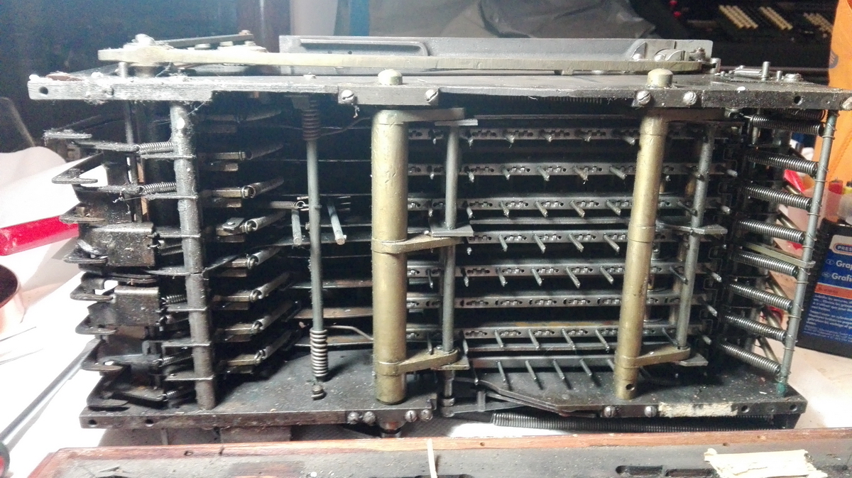
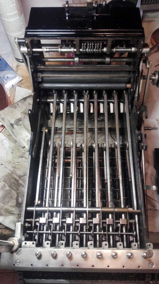
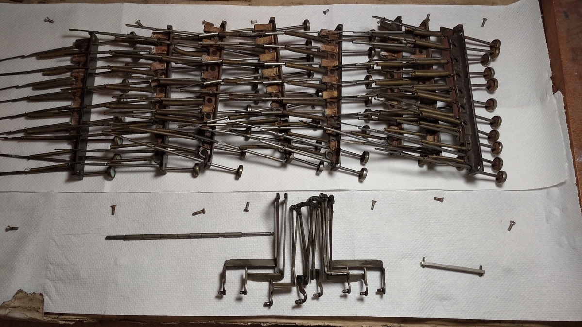
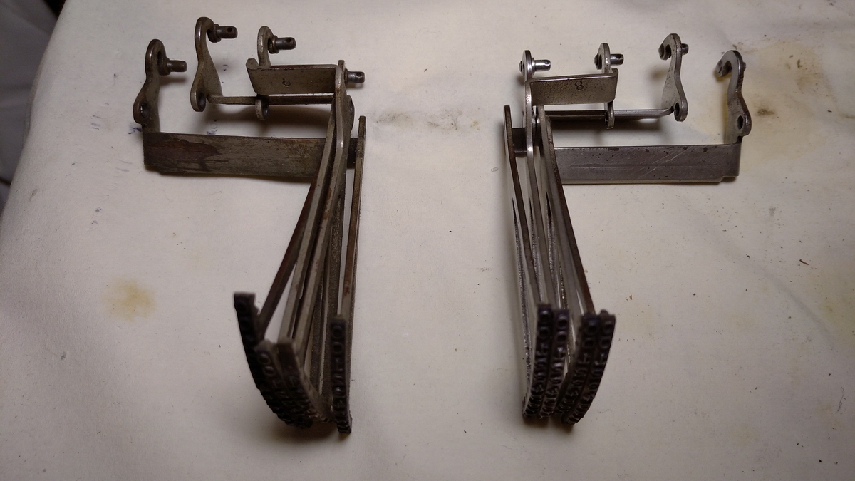
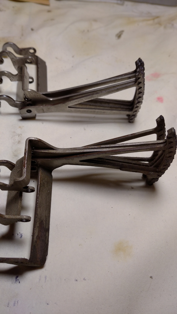
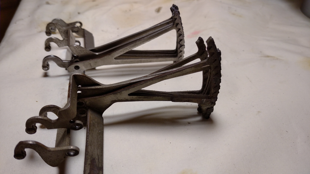
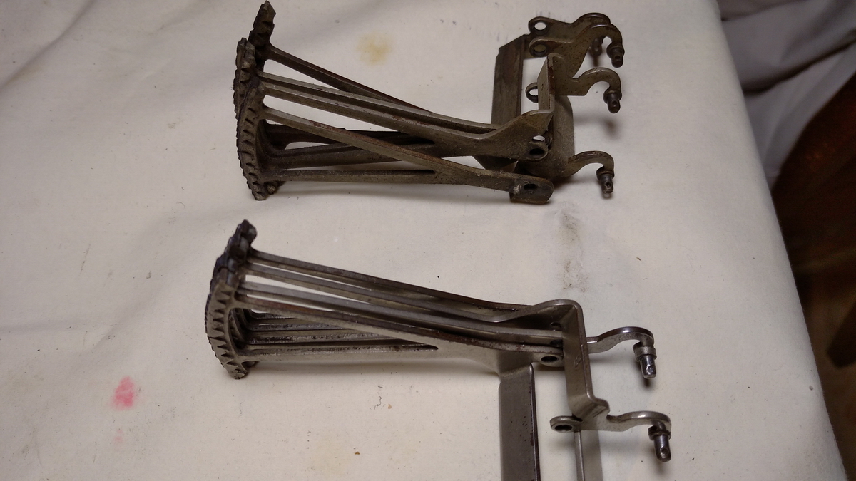
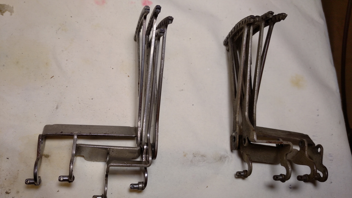
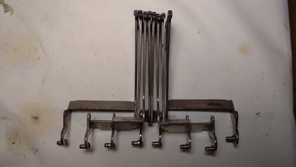
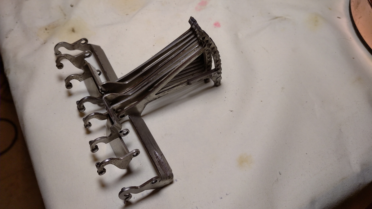
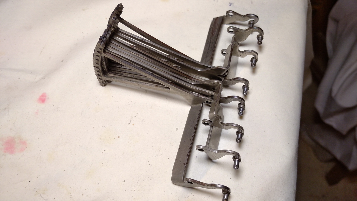
And the entire printing mechanism is now clean and set to the side before reassembly, in all its multi-legged spidery prettiness.
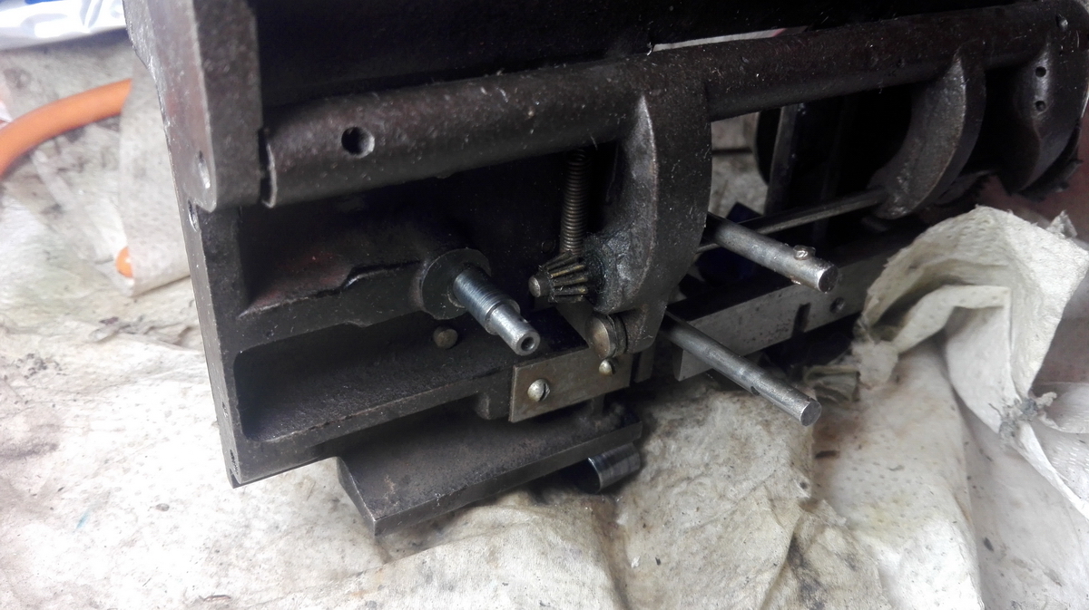
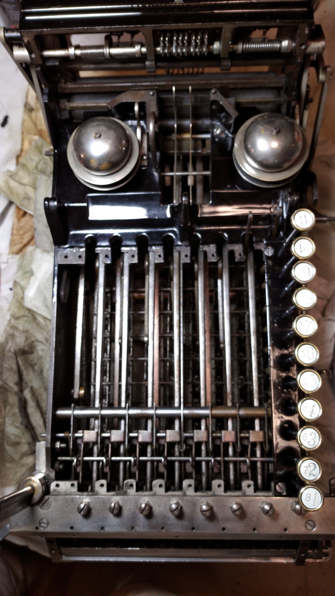
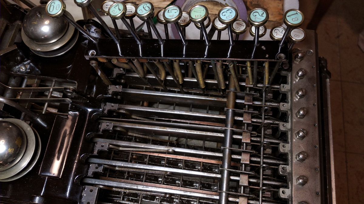
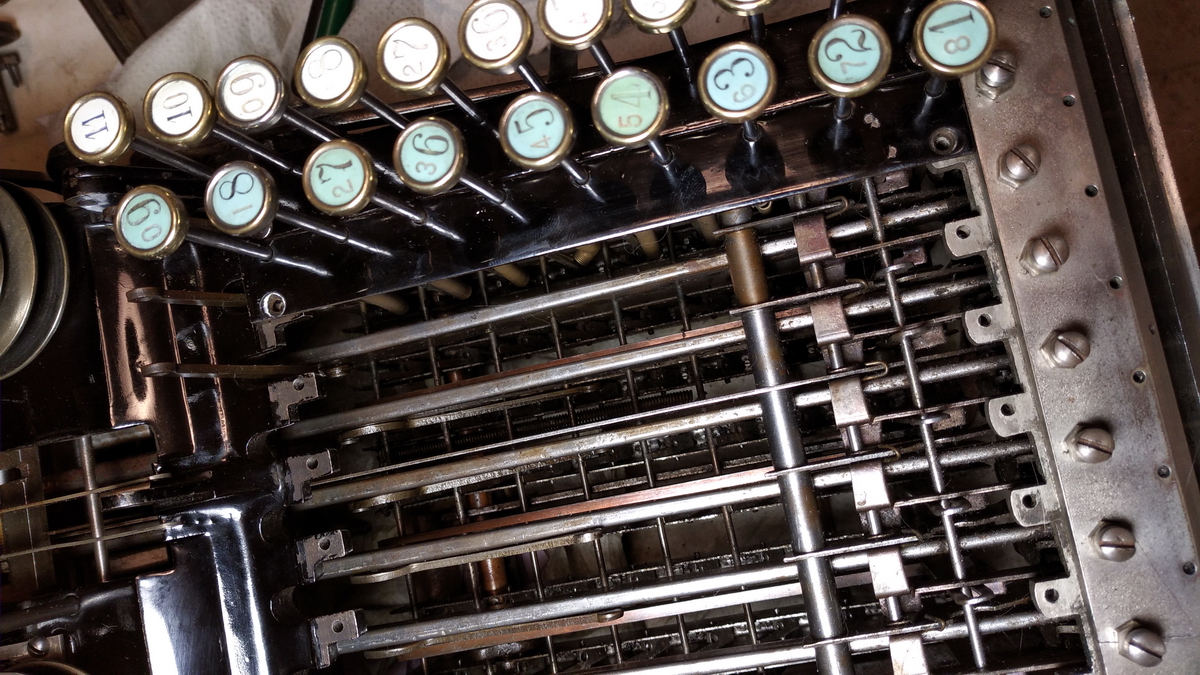
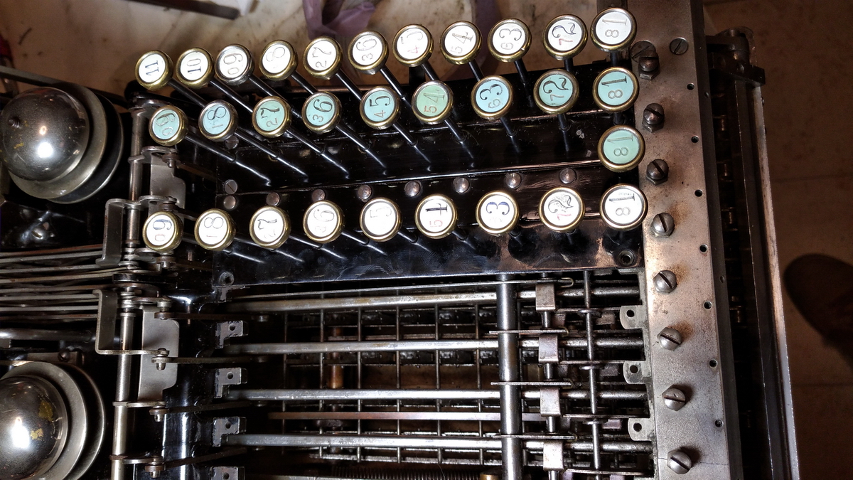
Then the shenanigans with the keyboard started in earnest. The orientation of the keys is fixed because of a half-round piece of bar at the very bottom end of the key, which slides into a half-moon shaped opening in the bottom rail.
...as can be seen on the right of this picture
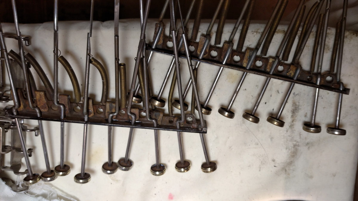
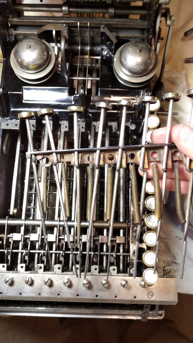
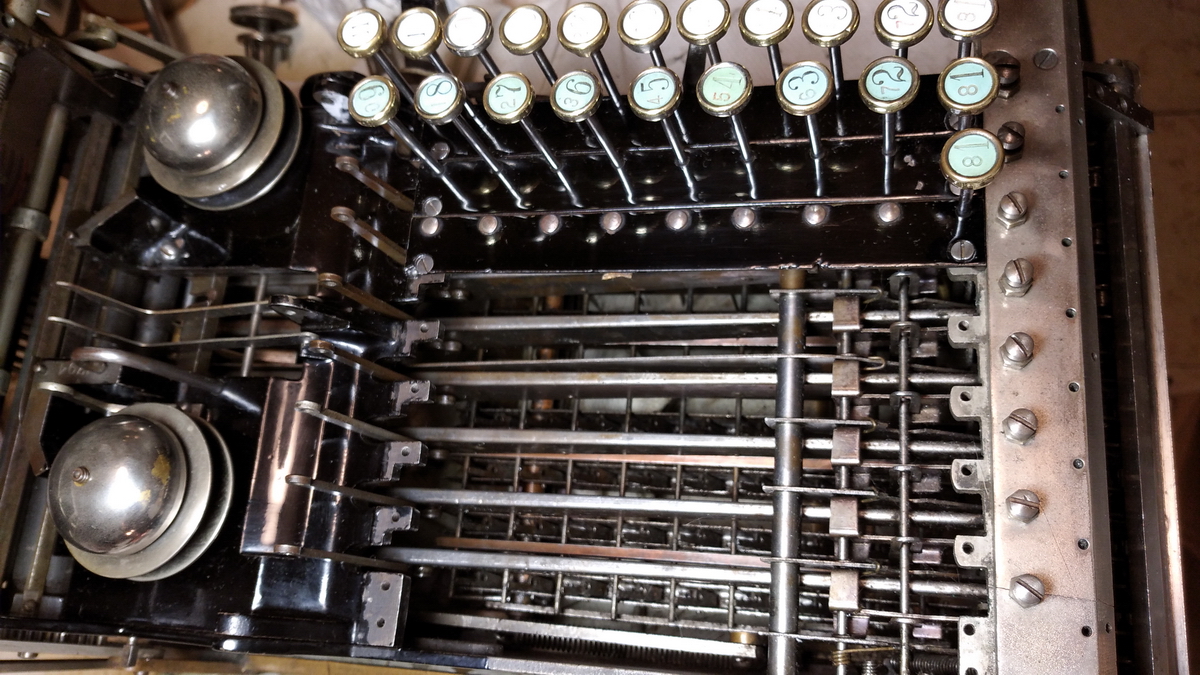
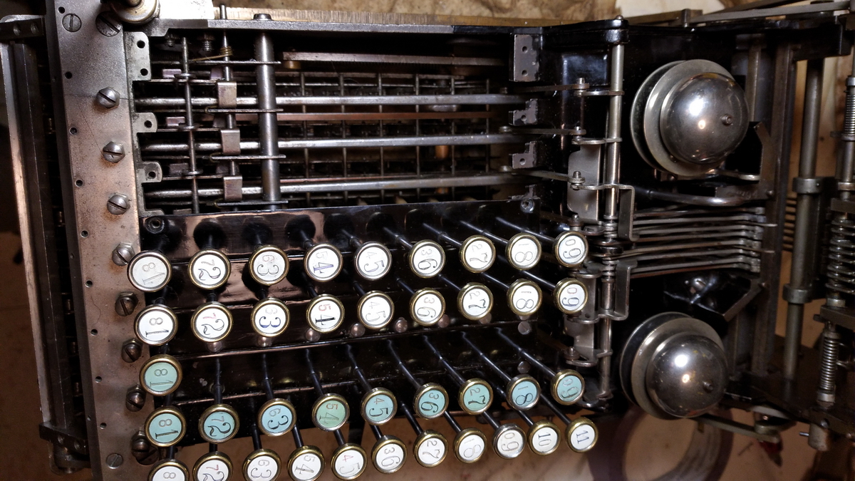
There is a spring-loaded catch that clicks the key into place once it reaches its full depth. But the keys themselves are not held straight into the top plate, but wobble around loosely, and threading 10 (or even worse, 11, like in the first row) loose rods that are off balance through all the right holes and into the right section of the bottom rail is ...well, I wouldn't call it impossible, because I managed in the end, but at least very very difficult. I am quite sure they had some kind of jig for this at the factory. In addition, the springs really like to come loose, and they do so without you noticing it. Also, I am quite sure there must exist a diagram on how exactly to route the springs, because if they are routed incorrectly, the machine will work fine, but some keys will be pulled downwards partially when the handle is pulled, and this looks a little odd. All in all, there are 3 keys in this machine that suffer this problem - see of you can spot them in the video at the end of the page.
So here the first row is in place.
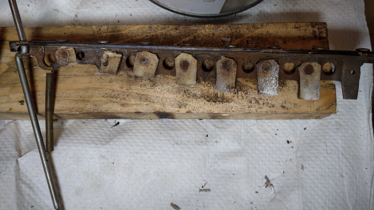
On to the next ones - still dirty at the front, clean at the back
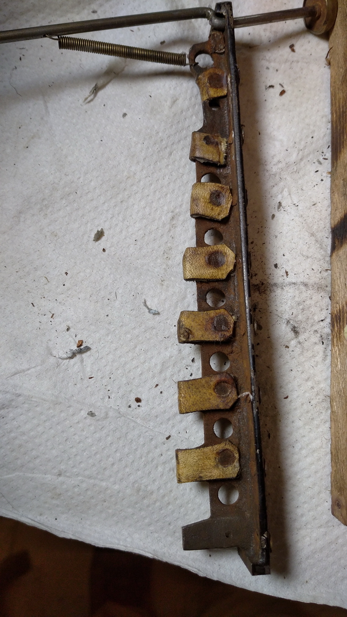
Dirty at the bottom, clean at the top. The leather buffers were given a good coat of nourishing wax.
So this is the next row...
Here's the 10 key for the shillings row... it's a standard part, so all the leather buffers are installed, but obviously they're unused.
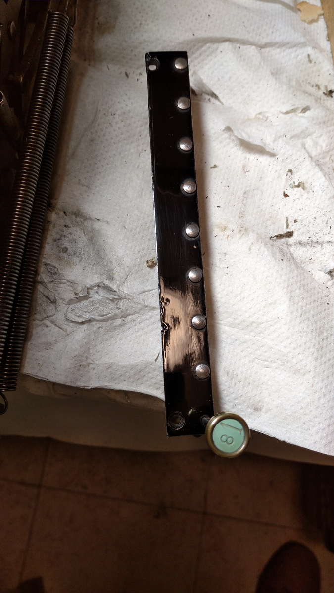
This was the easiest one to install...
I decided to continue with the printer assembly before continuing the keyboard.
Here are all the type bars in place. By not referring to the pictures I took before disassembly, I got the left 3 typebars wrong - the third one should be on the other side of the divider ... we'll find that out as soon as its assembled.
So these are the spacers, and this is the assembly process.

...and then of course it has to come apart again for switching that third typebar. That was quite easy by using a thin glass fibre composite rod to keep everything in place.
With the printer assembled and functional, from then on though, things went decidedly downhill.
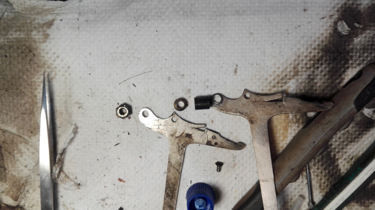
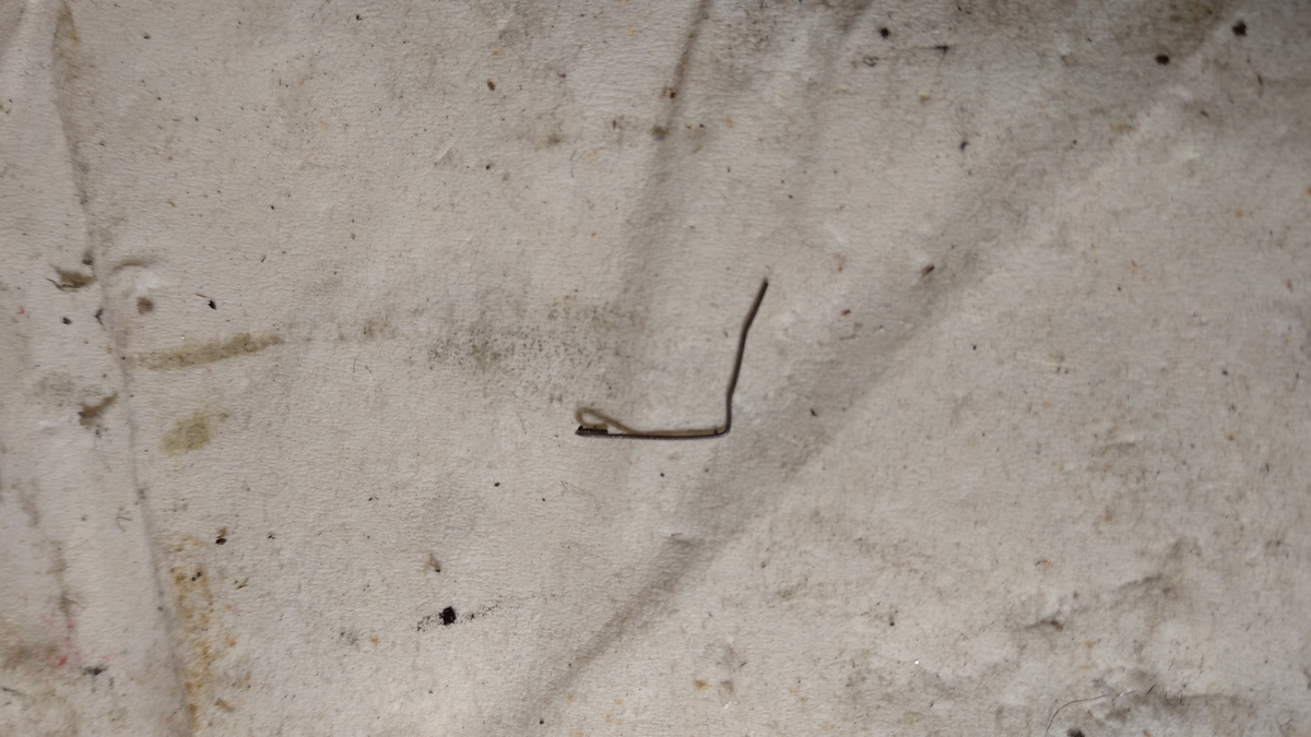
I spent 2 hours and 40 minutes accomplishing exactly nothing with the next row of keys. It kept going wrong over and over and over again ... then a screw jumped out and I lost it ... and then finally when everything was in its proper place, it turned out that the 9 key would not lock into place. I already mentioned the locking system - there is a catch in every key step, and spring-loaded pivoting levers in the bottom rails. When the catch goes past the bottom of the rail, it clicks into place, and the keyboard release pushes the tops of all these pivots forward against the spring pressure to release all the catches. However, this catch wasn't springing. So all had to come out again, and a little more investigation done. With the machine on its back, it is obvious that the tiny piece of spring loop that takes care of the springing was held by two metal tabs, one of which was broken, which allowed it to shift, and obvious then it doesn't spring. There's one more key with some difficulty in locking - I suspect a weak or slightly dislocated spring there, but I haven't looked into it, as it can usually be made to work after a few tries.
At this point I gave up in disgust.
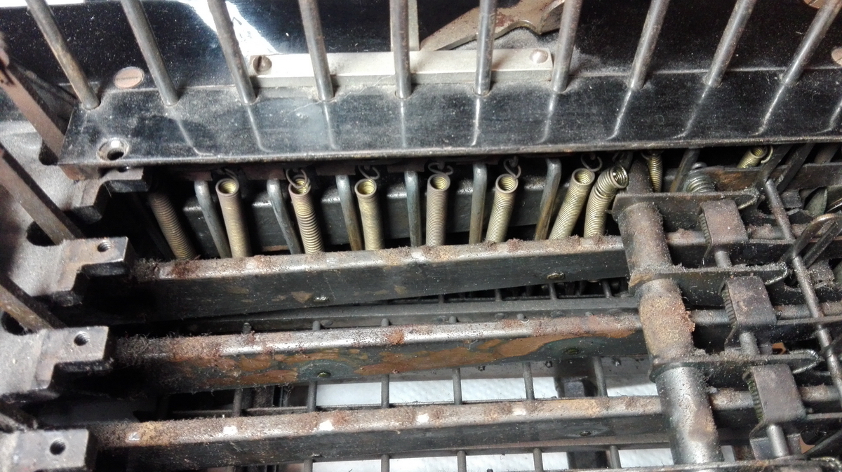
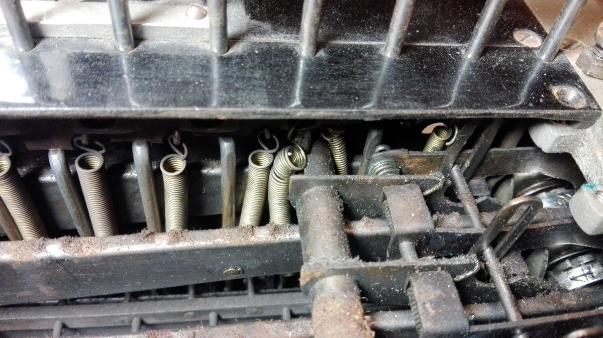
The next day went a little better. First of all, I located the wayward screw and returned it safely to its storage location. Luckily now, we have an entire keyboard row of these little springs to experiment with, that is entirely unused because this is an english model comptograph, which has a shillings row with only one key (but a full complement of catches and springs). So I disassembled one from that row to have a good look.
Because one of the metal tabs was broken and I broke the other one in the process of disassembly, I decided to stick the tiny spring back in place with a bit of cyanoacrylate glue, after a thorough degreasing with carb cleaner.
Not exactly period correct, but far preferable in my book to try to weld or silver-solder it when I can't get the part out. A piece of tape held it in position until the glue set, and now it works again as it should. Two more keyboard rows were assembled without too much drama in under an hour, and so there are now three more to clean up and reassemble, before we can turn or attention to the accumulator mechanism at the front, the wooden case and the ink ribbon.
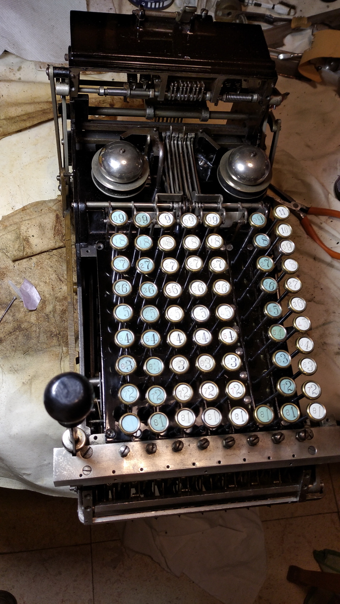
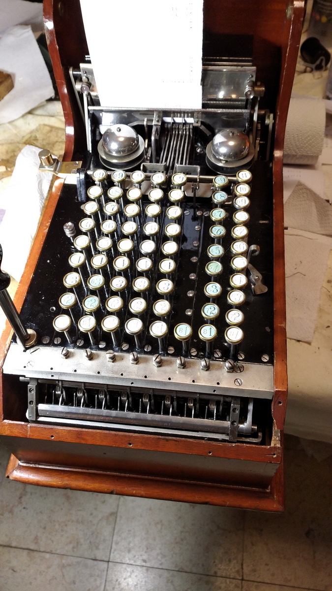
After the last keyboard rows went back in succesfully, and the wooden case was cleaned and waxed, the next step was to get the machine back in the box - because the wooden box is essential to hold the clearing mechanism, and it cannot be tested with the machine outside the box.
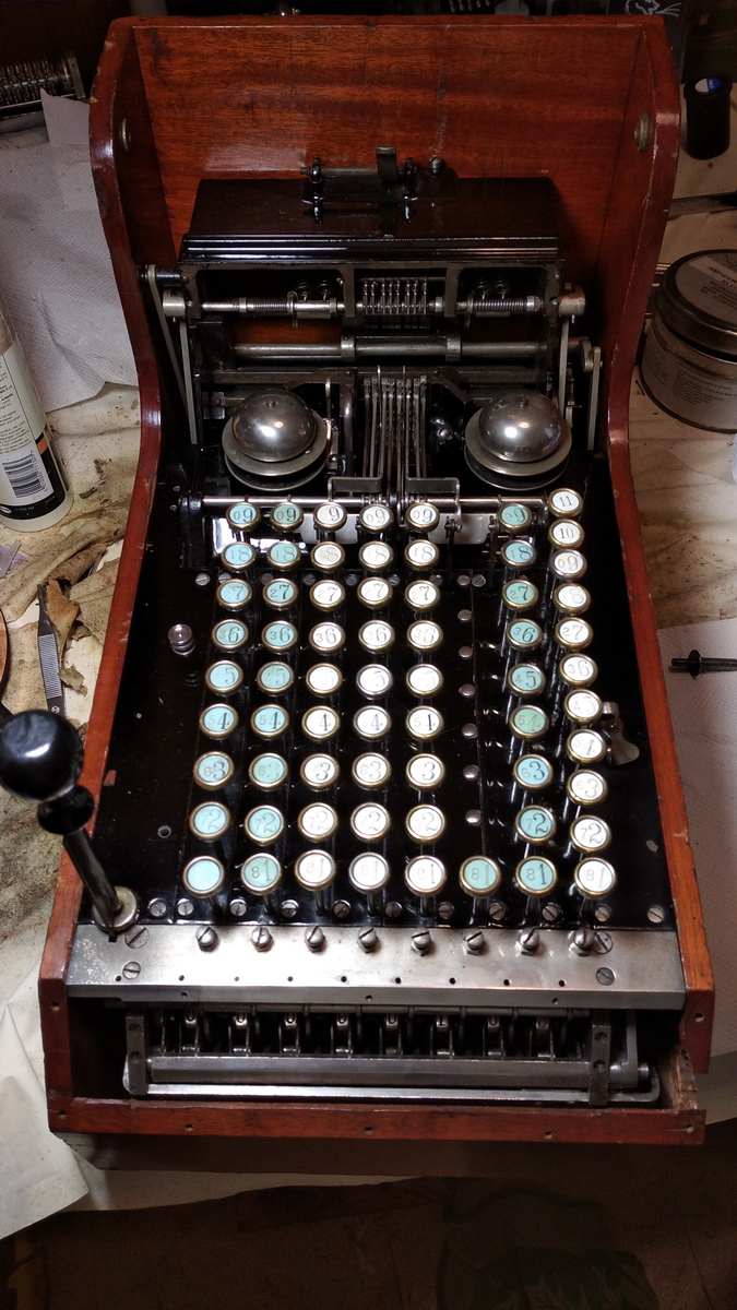
Some bits still needed polishing, but this was quickly accomplished ...
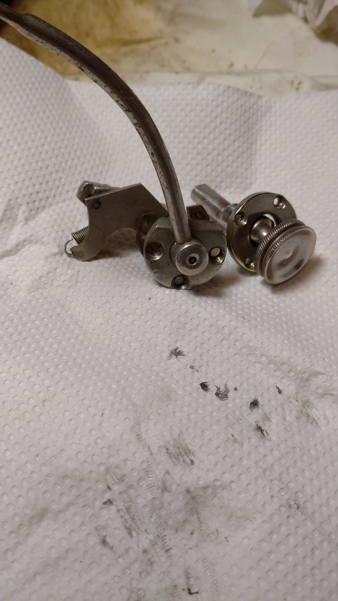
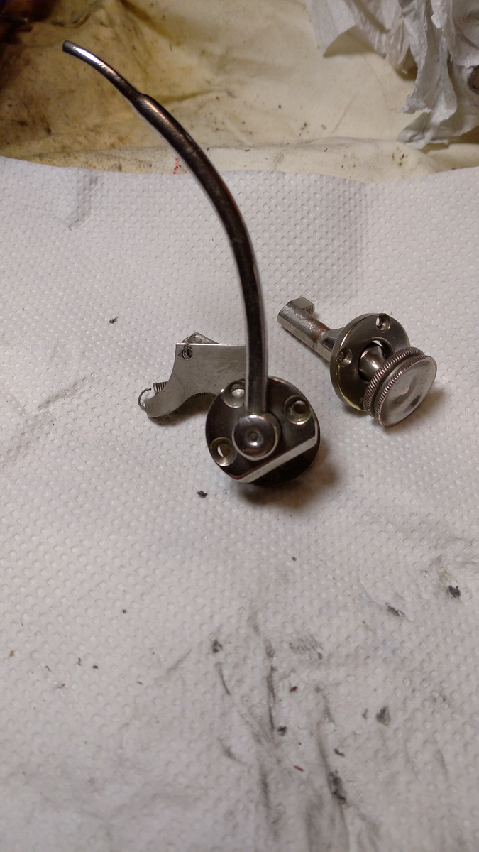
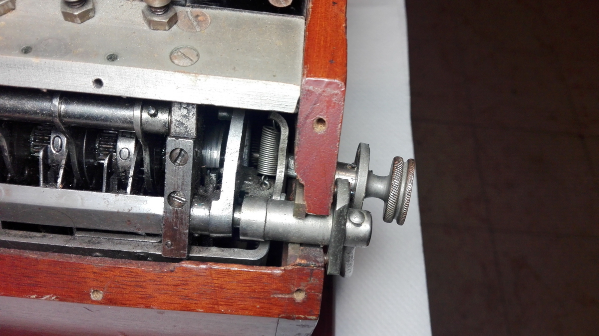
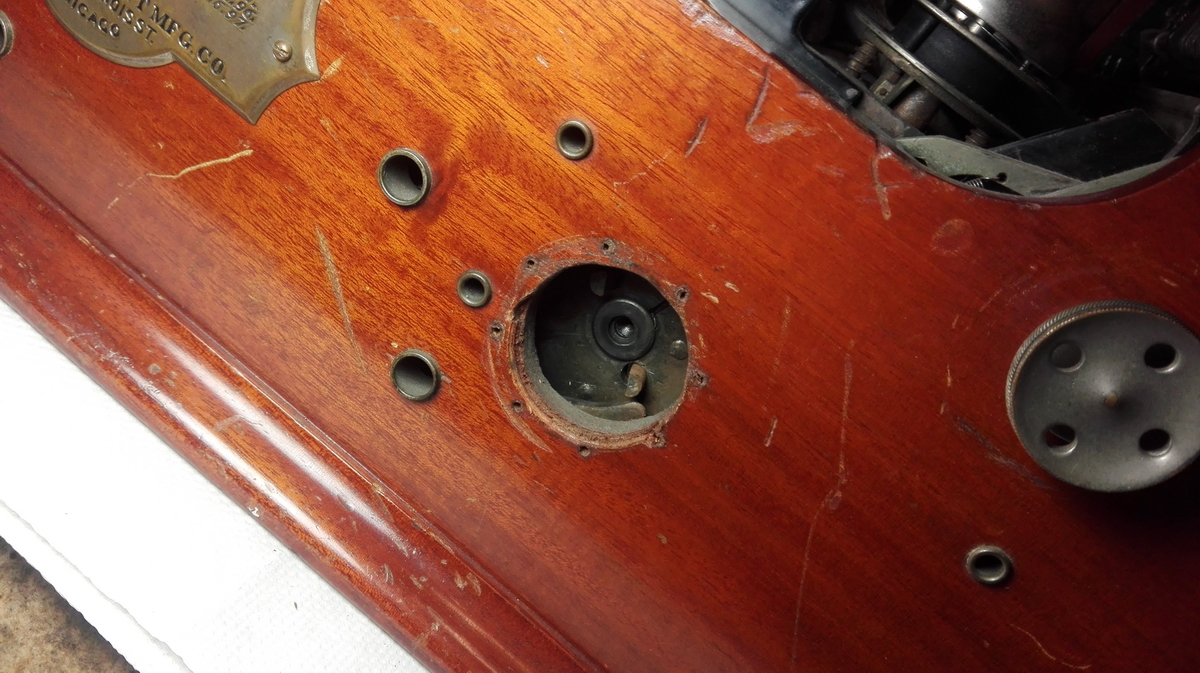
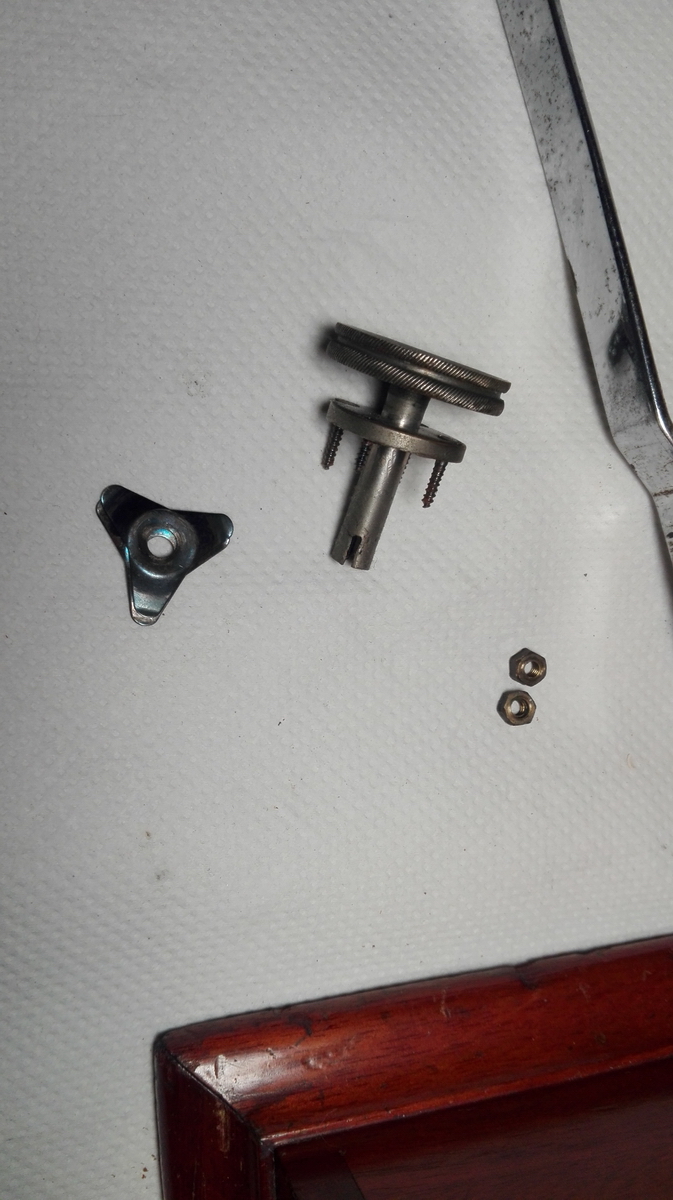
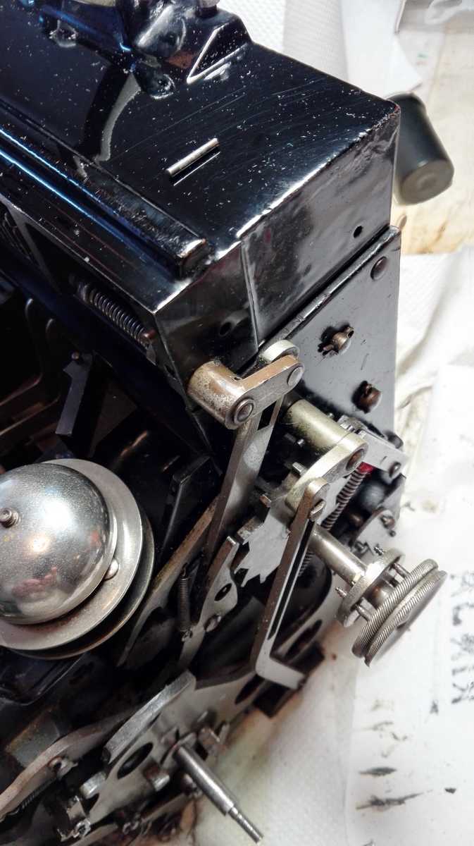
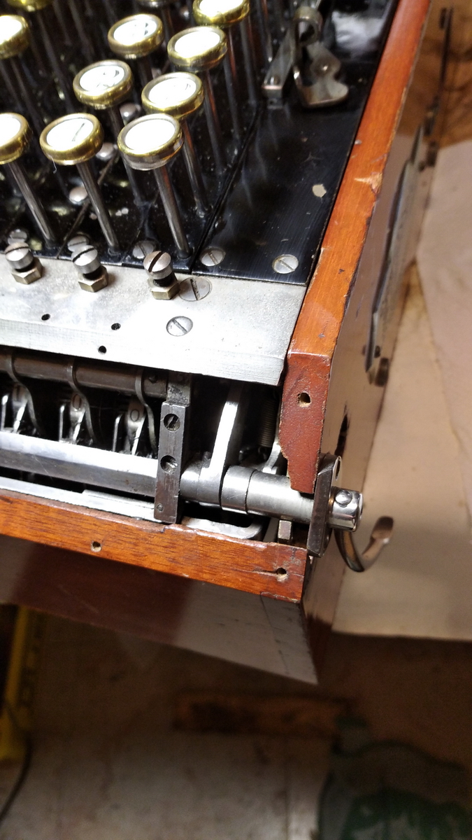
And then it's on with the assembly! The round knob just screws into the case with four wood screws, the lever is clamped in place by a brass collar at the back and 3 machine screws.
These are the final bits to be put back on:
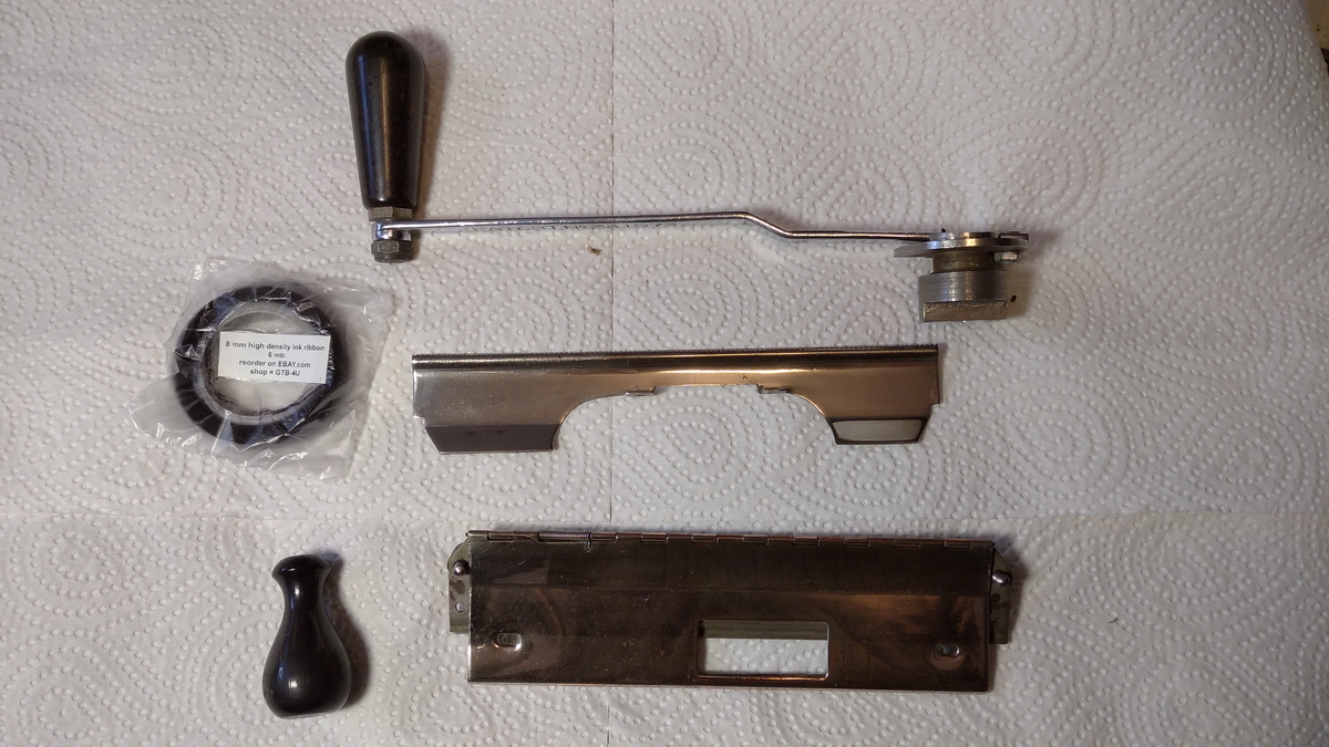
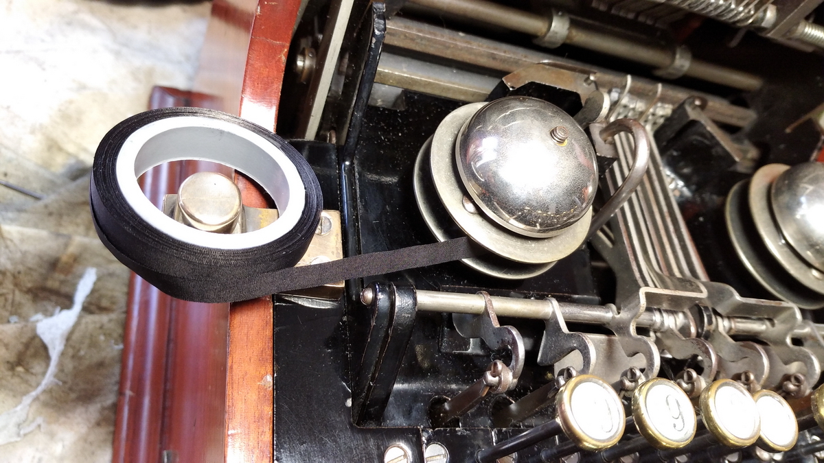
The ribbon was sewn in place and the ribbon holder used to good effect to roll all 8m onto the spools
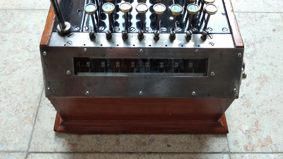
With the machine back in the box, the clearing could be tested. This almost worked, but not quite. Something else that was a complete disaster was the alignment of the type. As you can see, it is quite messy.
This is where I made a few mistakes. I assumed that the screws and nuts in front of the keyboard could be used to adjust the position of the type segments to line up, so I started tweaking them, and initally obtained quite good results. When everything was lined up, it turned out that there were two problems left - the result register didn't clear reliably, and some of the carries were quite sketchy, needing a little nudge, and of course that is not what you want when everything is shielded behind glass.
In order to understand what went wrong, I need to explain how the Comptograph accumulates and records, because the system is quite different from an ordinary comptometer. The reason for this is that Dorr E. Felt was not limited to the energy input from pressing the keys for effecting the carries, as he was in his key-operated machines. Here we have a whopping big handle that we can use to deliver quite a bit of energy into the machine, and hence carrying should actually be quite easy - and it is. However, there is another issue, which is the recording, where whatever value that is in the accumulator should be transferred to the printing mechanism, without changing the values in the accumulator.
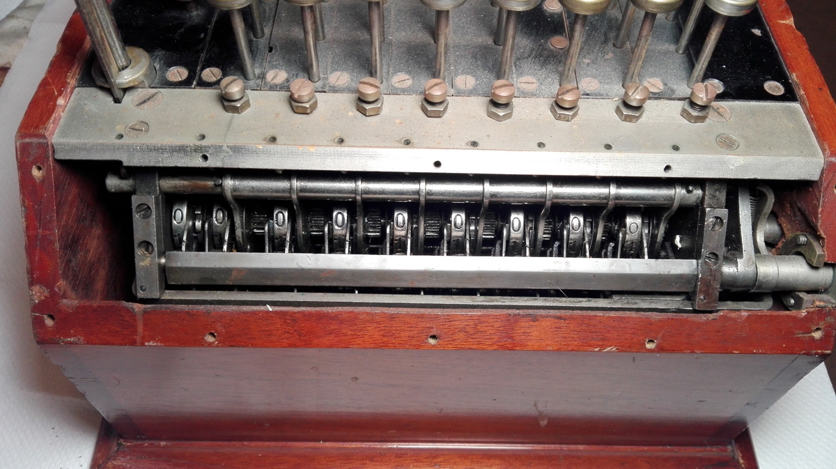
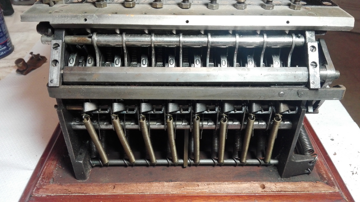
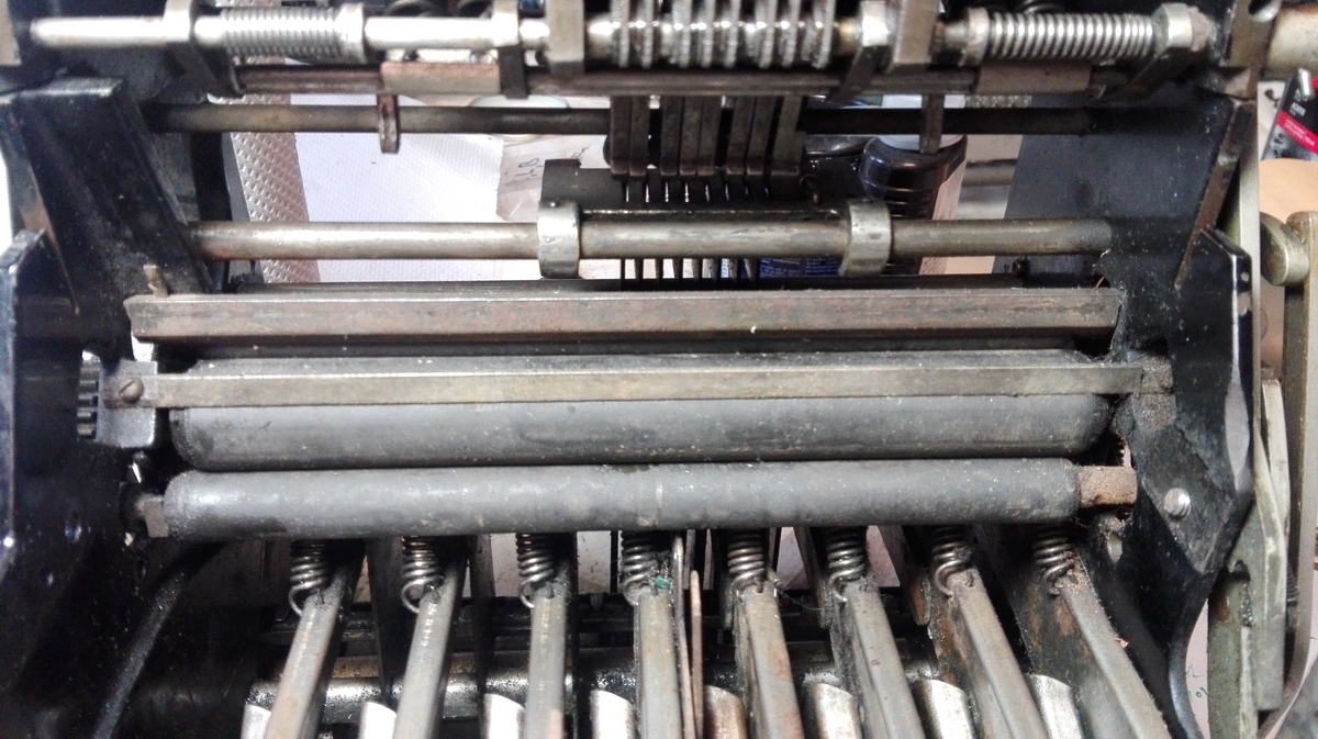
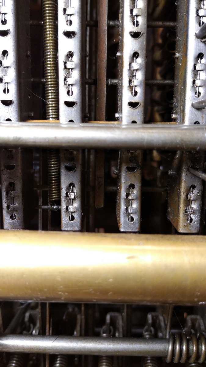
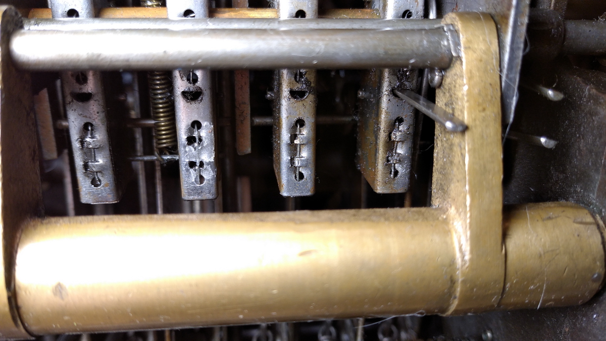
In order to understand how this works, it is probably best to have a look at some of the patent drawings, and then compare to what the actual machine looks like. In the patent, the tens' carry is hardly discussed, as this was not new, and probably quite similar to how Burroughs and other non-key-operated adding machines did it. Hence, the patent drawings don't teach us much, but we can see how it works in practice. It is very difficult to look into the mechanism of the accumulator, because our view is limited by two bars running left to right in front of the register.
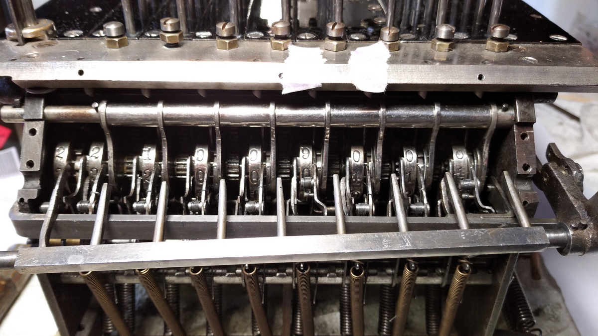
However, these bars can be carefully removed:
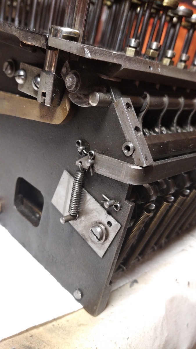
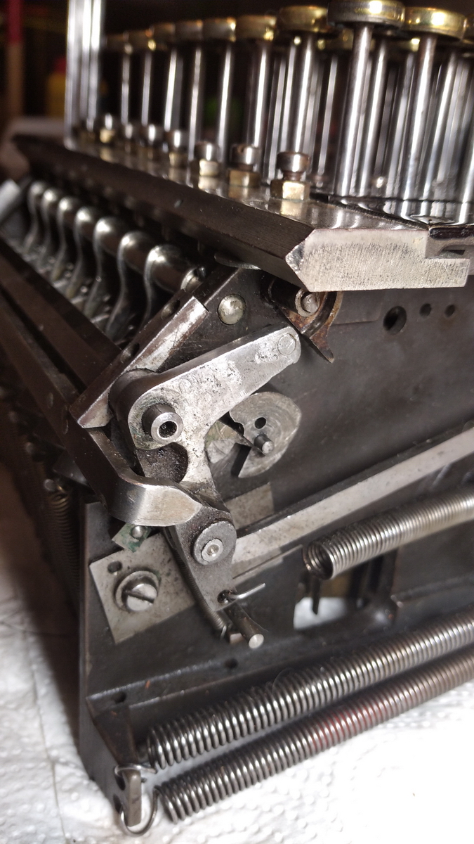
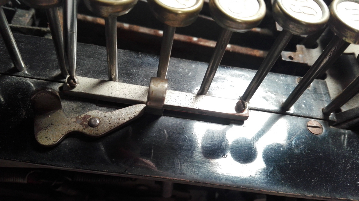
This is the top (rocking) bar, which has long teeth extending downward that operate the tens' carry fingers and locking of the result wheels.
Its function is to hold back (and on occasion lock into place) the tens' carry fingers and locking devices. It does that under two circumstances: 1. operated by the long downwards lever on the right side of the machine when clearing the register, and 2. during part of the cycle of the machine when adding numbers from the keyboard, to prepare the carry fingers for a possible carry.
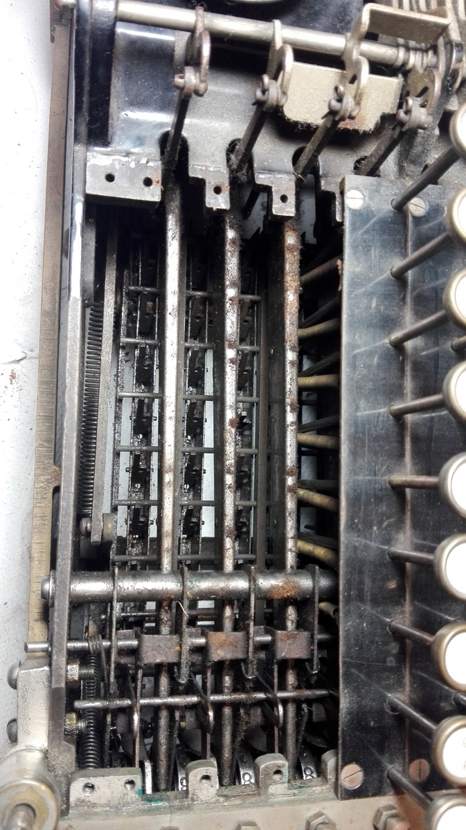
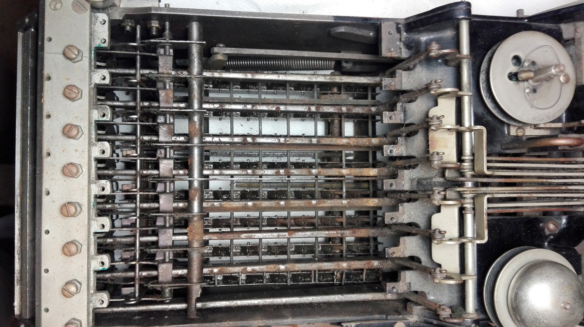
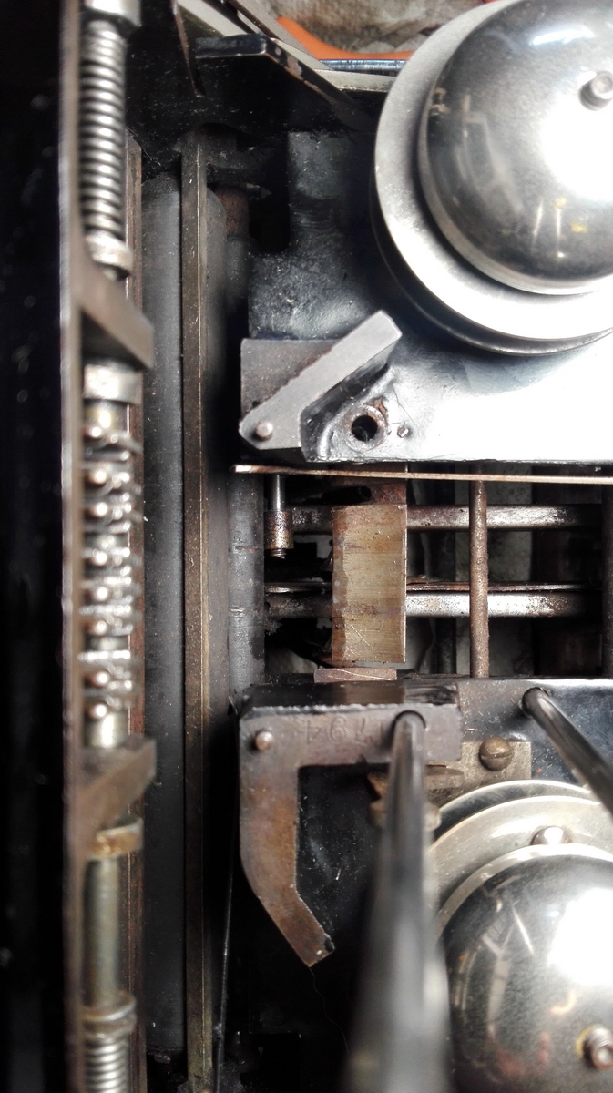
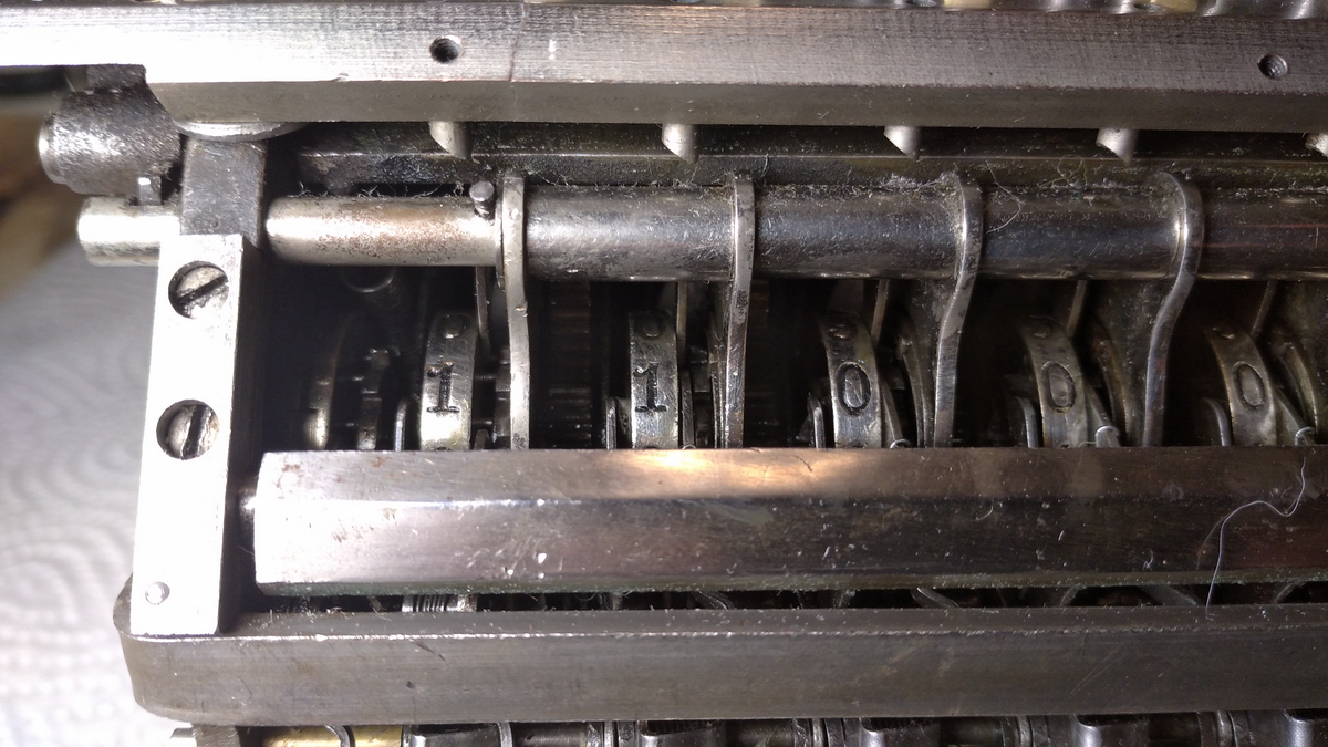
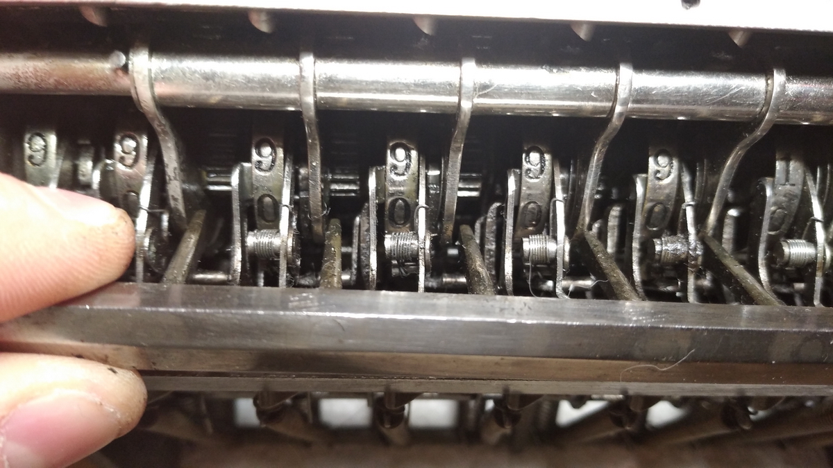
The carry fingers can be seen in the following picture. In the middle result wheel, with the 5, the carry finger is forward - a carry has taken place. It is the part directly to the right of the result wheel. In all the other positions, the carry fingers are under tension and locked, and pointing backwards. This is the effect of the top bar tilting, and pushing the flat support for the carrying fingers out towards the front of the machine, where it locks.
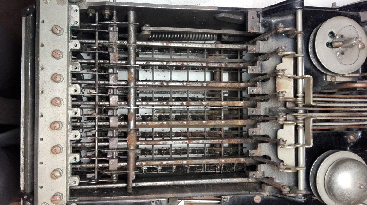
This is the same picture from another angle:
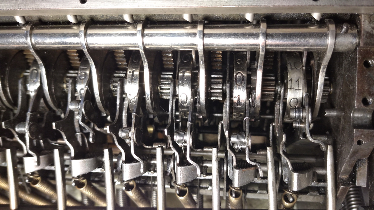
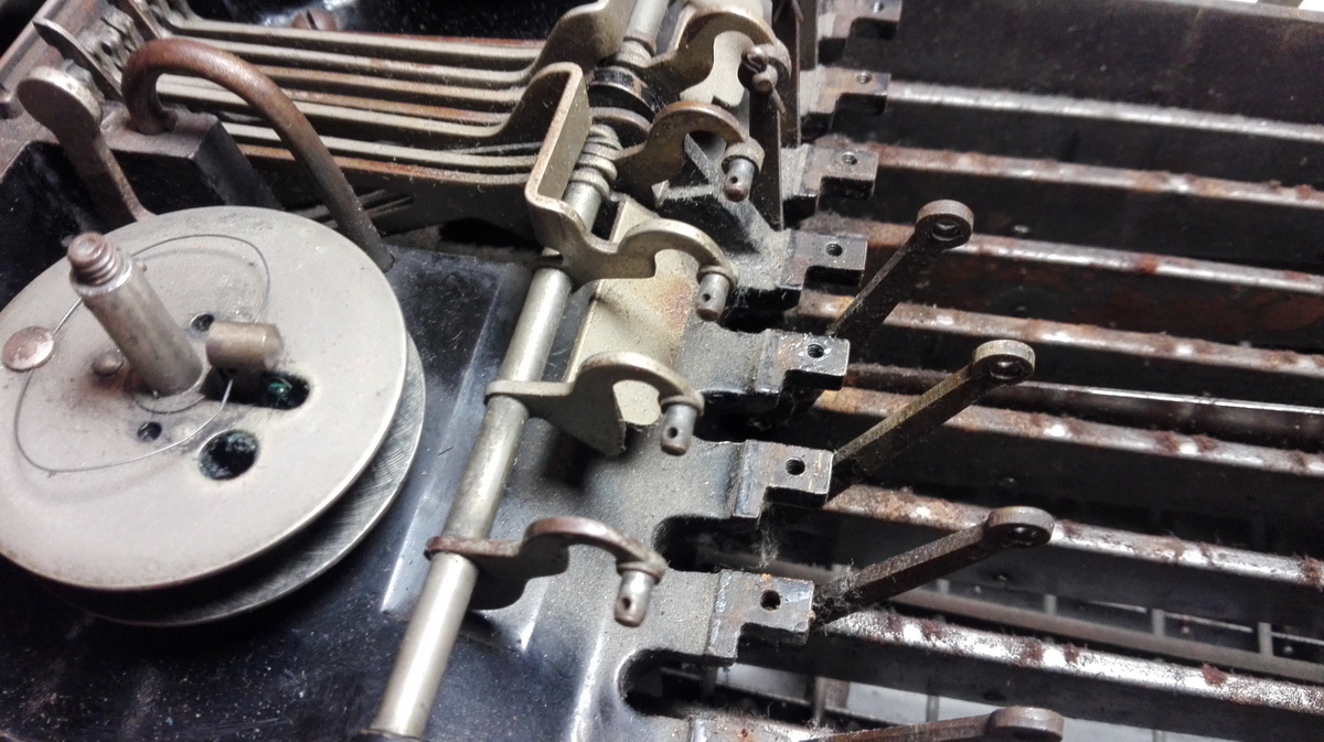
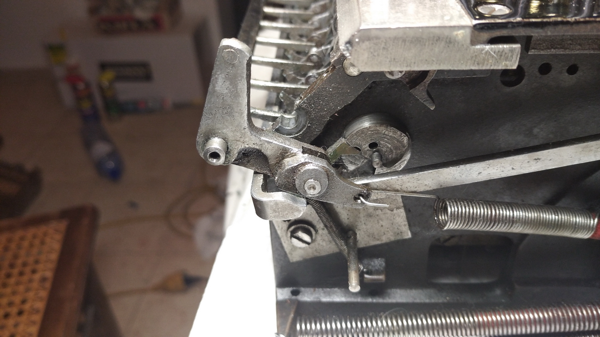
And this is the rightmost column, where of course a carry can never occur, but the device only serves as a locking device. Hence, it also doesn't lock towards the front of the machine. This makes it excruciatingly difficult to operate the machine when the two bars at the front are not in place to release this lock (and the one at the far left end of the machine on the "overflow" wheel, because there is very little space to get in there with a screwdriver and unlock it manually).
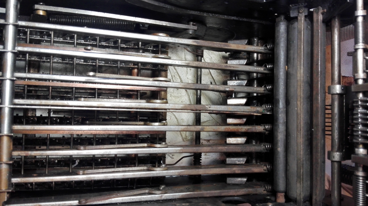
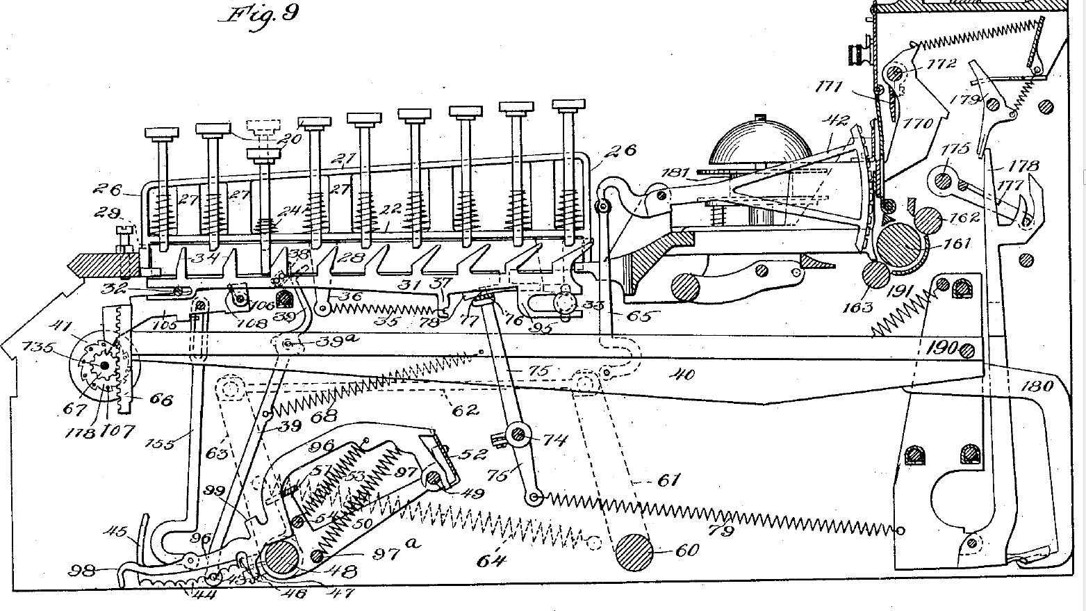
So during the first part of an addition cycle, these tens' carry fingers are pulled back, and the result wheels are unlocked. As can be seen in the Figures in the patent (n° 749 177, Jan. 12 1904), there are swinging bars with a gear sector at the front, which are pulled downwards by the crank in proportion to the number set in the keyboard (the keyboard mechanism is actually different in this machine than what is pictured in the patent) and are always meshed with a small gear on the right side of the result wheel. The other end of the swing bar is connected to the printing mechanism, so that any number entered into the register is also recorded at the same time.
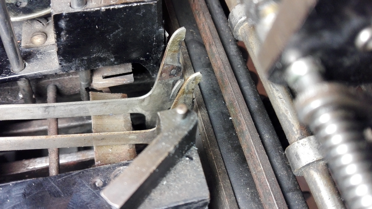
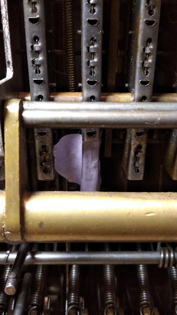
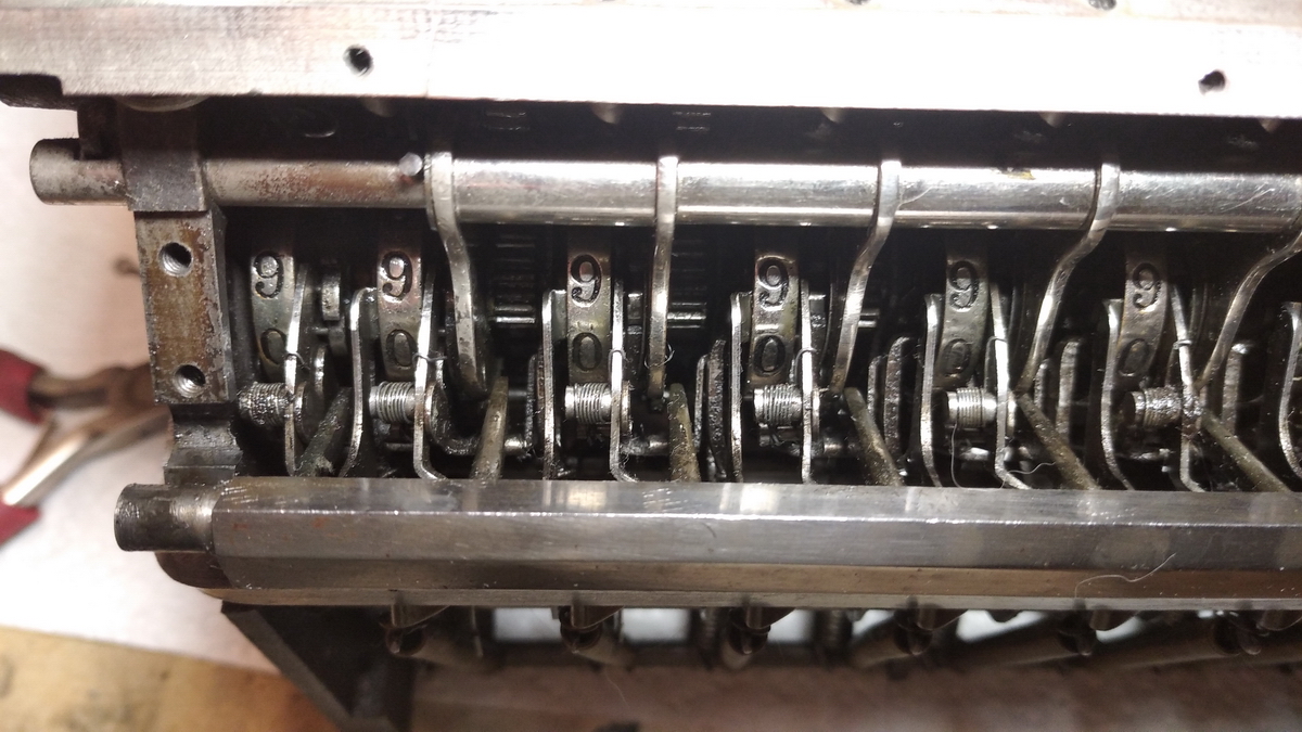
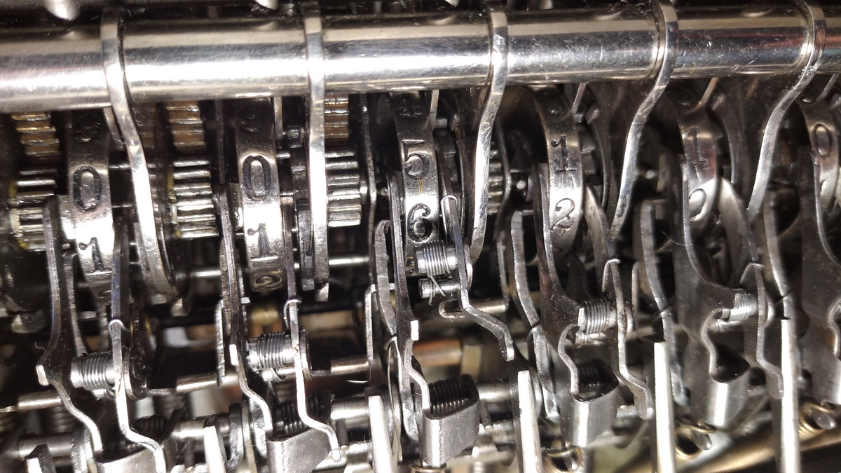
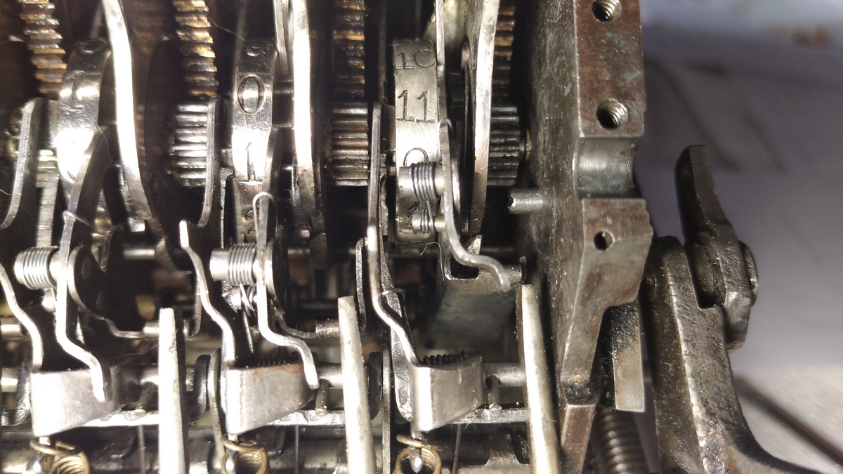
The other steel part on the left side of the result wheel reaches into the hollow result wheel, and can be lifted backwards by a tooth on the inside of the wheel corresponding to the change from 9 to 0 (when a carry should occur). In the following picture you can see this finger pointing into the result wheel with the number 11. If you follow this finger out of the wheel, you will see that another part locks with it at its underside, in a tiny slot.
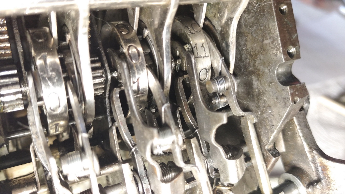
The part that engages with it, is the lock for the tens' carry finger on the next result wheel, so as soon as the tooth on the inside of the result wheel pushes the feeler finger, this lifts up, the tens' carry part for the next result wheel falls out of the slot, and the tens' carry finger shoots forward, pushes the result wheel one position ahead, and then immediately locks it in place.
It is probably much easier to see how this happens in a video:
The mechanism for "reading" the result mechanism and uncoupling the geared sectors and gears from the result wheels is pictured in the following figures in the patent:
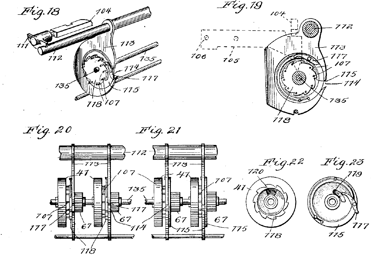
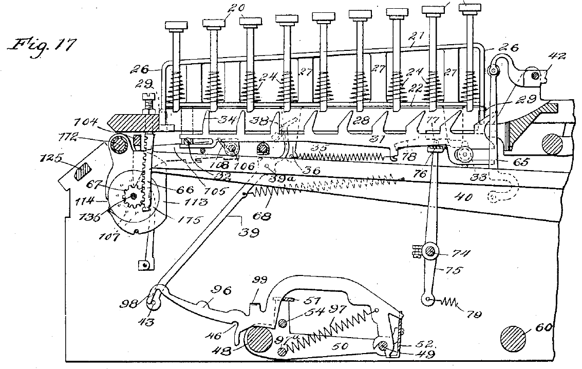
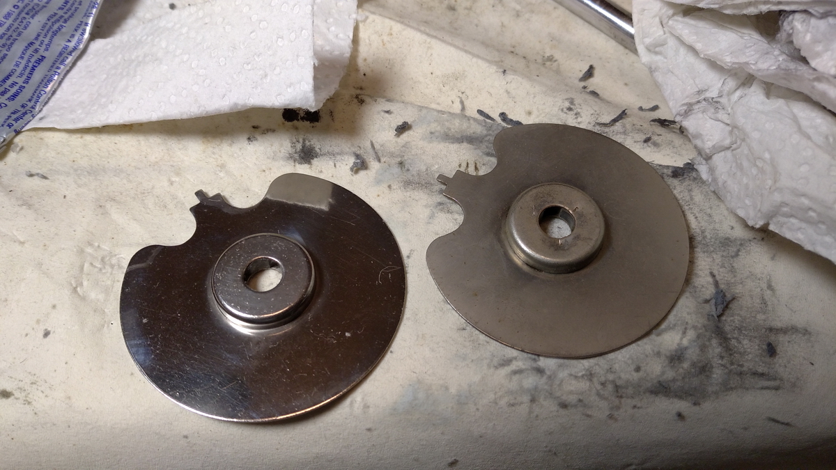
The result wheel is not directly coupled to the gear which is operated by the bar that comes from the keyboard, but by means of a ratchet 118 and pawl 117. This pawl is pivoted on a so called "answer disk" 115. The disk and the ratchet are otherwise unconnected, but as long as the pawl is bearing on the ratchet, when the answer disk rotates, so does the ratchet and the numeral wheel. However, if by pushing the "total" lever down, the "answer rings" 113 are shifted to the side (compare figure 20 and 21), as soon as the answer disk is starting to rotate now, the pawl is lifted off the ratchet by the inside of the answer ring, and the result wheel remains stationary. On the right side of the ratchet, and hidden from view completely, is a pocket with a sharp edge 120, with which a spring loaded second pawl 119 on the side of the answer wheel engages as soon as it meets it, and stops the answer wheel dead in its track, because the result wheel with whicht he ratchet is coupled is positively locked in place by a lock operating during the printing (the dashed outline 104 - 105 -106). Depending on the position of the result wheel, and hence also that of the ratchet, this takes less (position 1) or more (position 9) of a complete rotation, so that essentially the accumulator is read out in this way, and the result transferred to the printing bars. Also this process is shown in the following video:
Now, all that is good and well, but what went wrong then? It turns out that the locked screws in front of the keyboard do not just adjust the height of the typebar - by bearing on top of the geared sector at the front, which is always engaged with the gears in the result register, they also rotate the answer disks slightly, and in effect must be used to line up the end of the pawl 117 with the slot in the answer ring. If this is not done correctly, it has disastrous effects on the carry and clearing, because even a slight amount of friction is enough to throw everything off (not to mention that if all the pawls do not line up, printing is blocked, and serious damage can be done to the machine). The printing sectors themselves also are slightly weirder than one would expect. If you go and look back at them, then the only printed numbers that are not positively located by the lifting mechanism are the trailing zeroes. This is why every printing bar has two zeroes - one which is printed with the bar at rest, and that should be regulated with the screws at the front (as long as the pawl does not move out of the window it needs to slide into). The second, "higher" zero is used when totalizing, and then the printing bars are lifted by one position anyway. After understanding this and regulating everything, the only printing bar that cannot be positioned perfectly is the rightmost one, which cannot be tweaked down enough to get a clear trailing zero. Other than that, everything more or less lines up.
After cleaning up and putting all the split pins back at the ends of the shafts, put the machine in the box, polish up the paper roll holder and the metal parts inset in the wooden box, and then reassemble the lot.
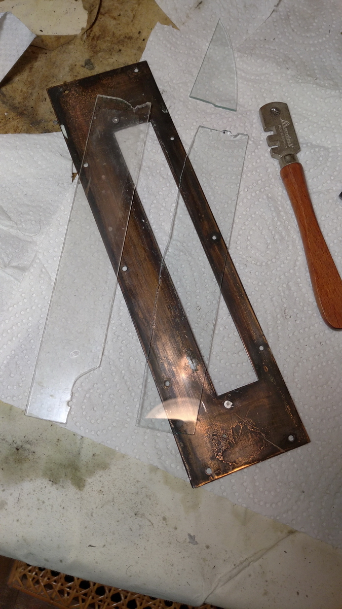
All that was left to do was to put new glass in the front metal plate of the machine, then put some toothpicks in the screw holes for the front plate to give some more grip to the screws, and put all the screws of the front plate back on - and that was the machine finished.
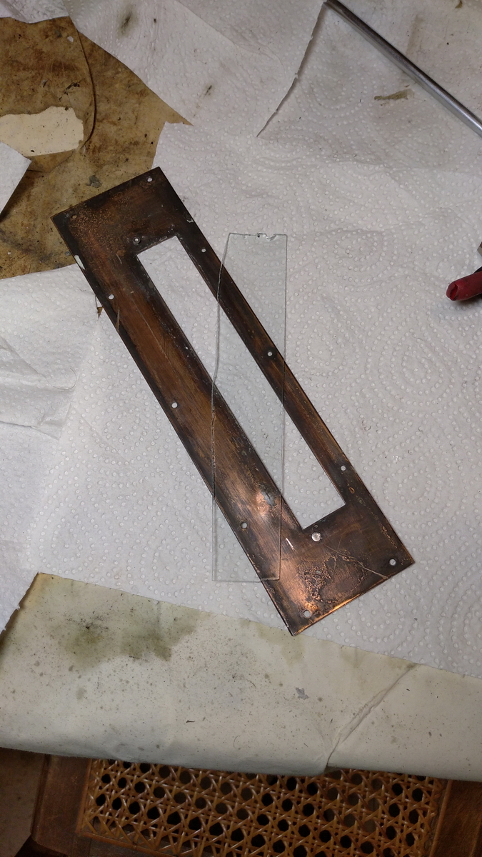
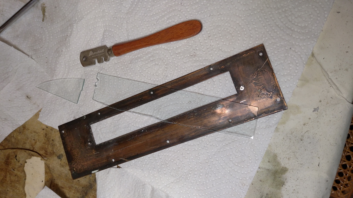
That's the plexiglass bit that was in there on the left side ...
A final dusting down, and a photo and video session concluded the restoration.
Some video:
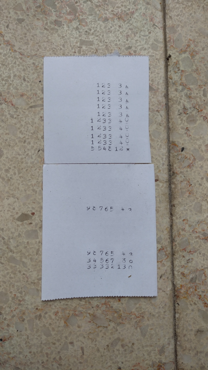
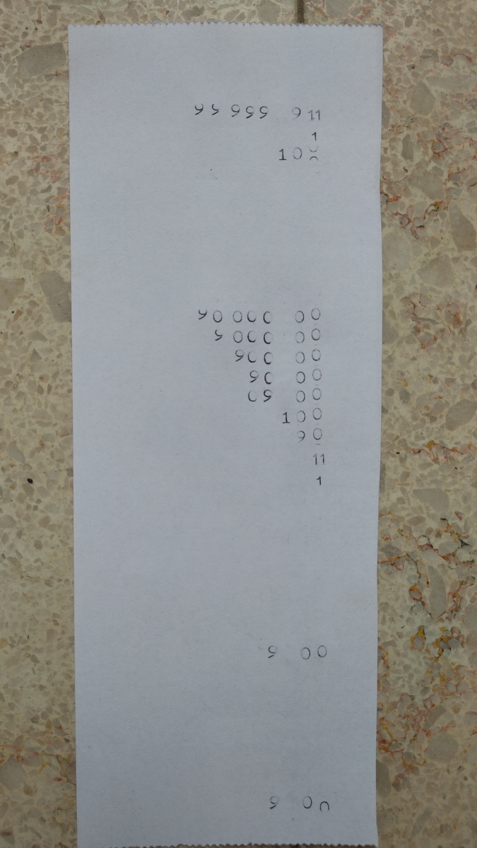
And then finally the strips of paper that were printed by the machine during the video. As already announced, I cannot find a way to adjust the leftmost pennies printing sector in a satisfactory manner. You can see that the machine handles carrying well, and generally manages to drop leading zeroes (also separately for the shillings), except in the one case where it printed 09 00 instead of 9 00 - which it did correctly the second time round. The last two entries on this strip also clearly show the difference between printing an intermediate result, in which the printing sectors stay at rest and the "lowest" zero is printed, resulting in only slight misalignment of the pennies column, and the printing of the total, in which the "highest" zero should be printed, and this is really out of alignment. Adjusting all the numbers up a little to where they should be by bending the type bar then results in a "split" zero in the final position during printing of intermediate results, because the type bar is now too high for printing the "lowest" zero. Strange ... The sample print found under the machine has no trailing zeroes anywhere in the pennies column, so we have no idea whether this issue could actually be solved whent he machine was new ... For now, we'll have to live with it. Who calculates in pre-decimal British currency anyway these days!
Well, that's it for this restoration - I hope you enjoyed that!