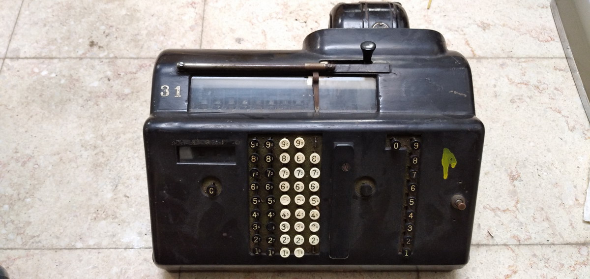
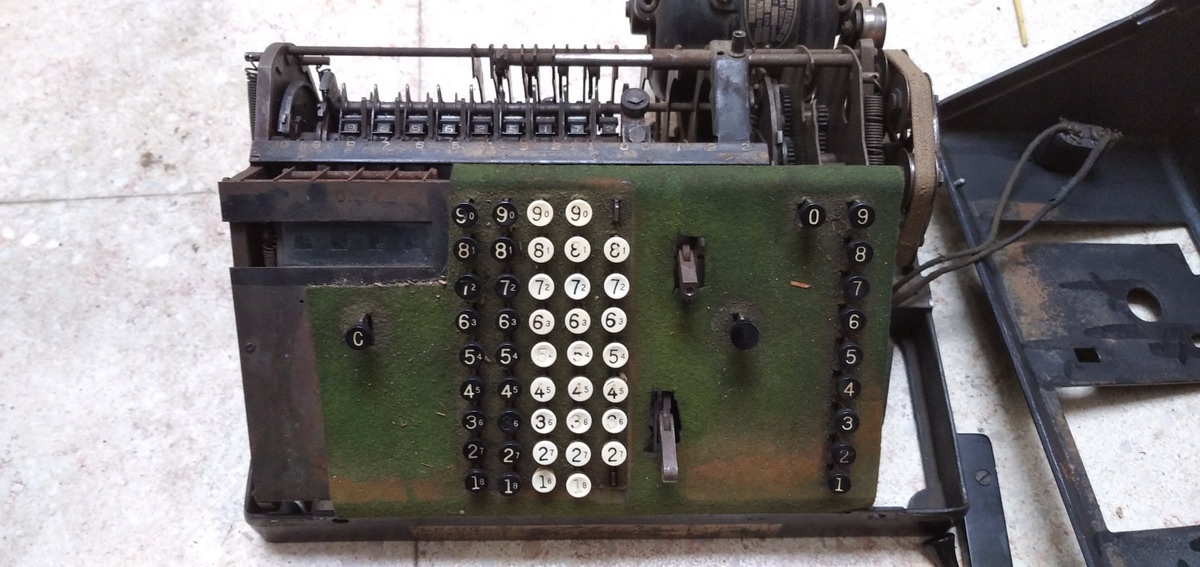
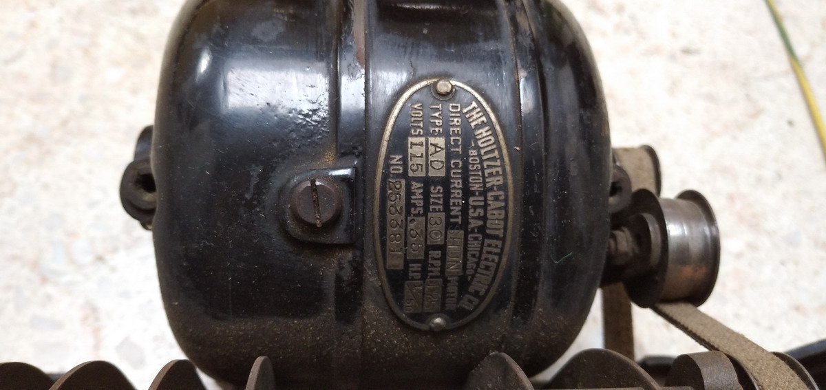
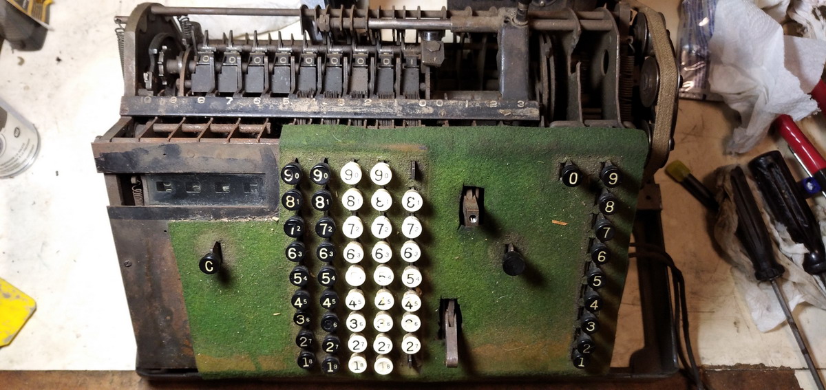
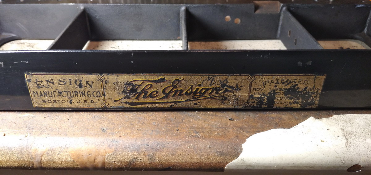
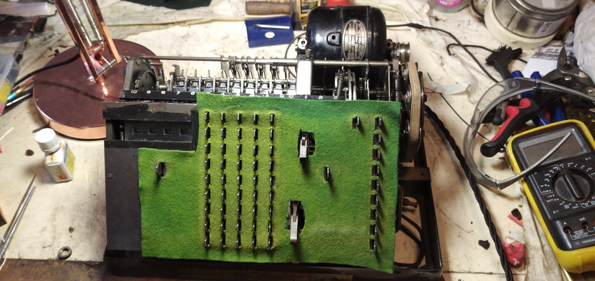
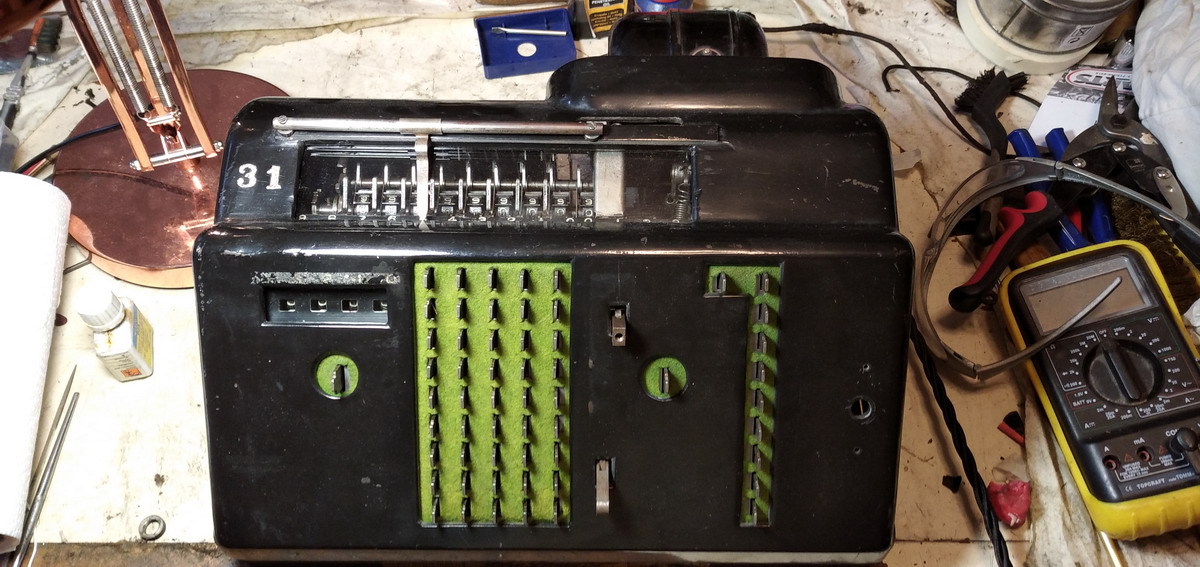
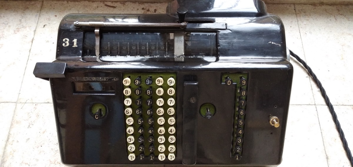
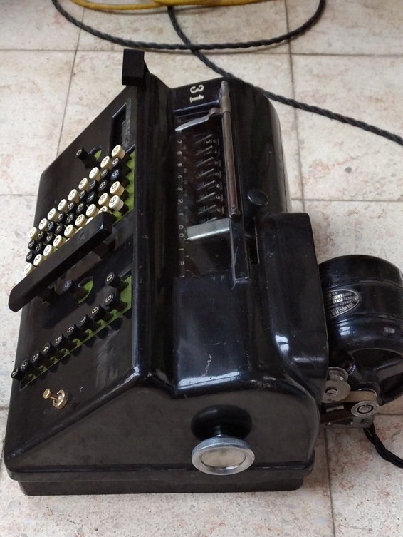
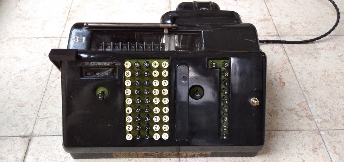
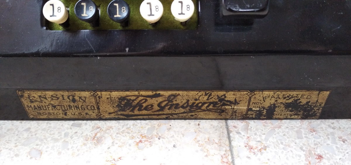
Ensign Calculating Machine model 54
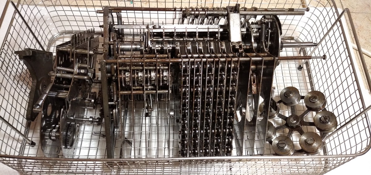
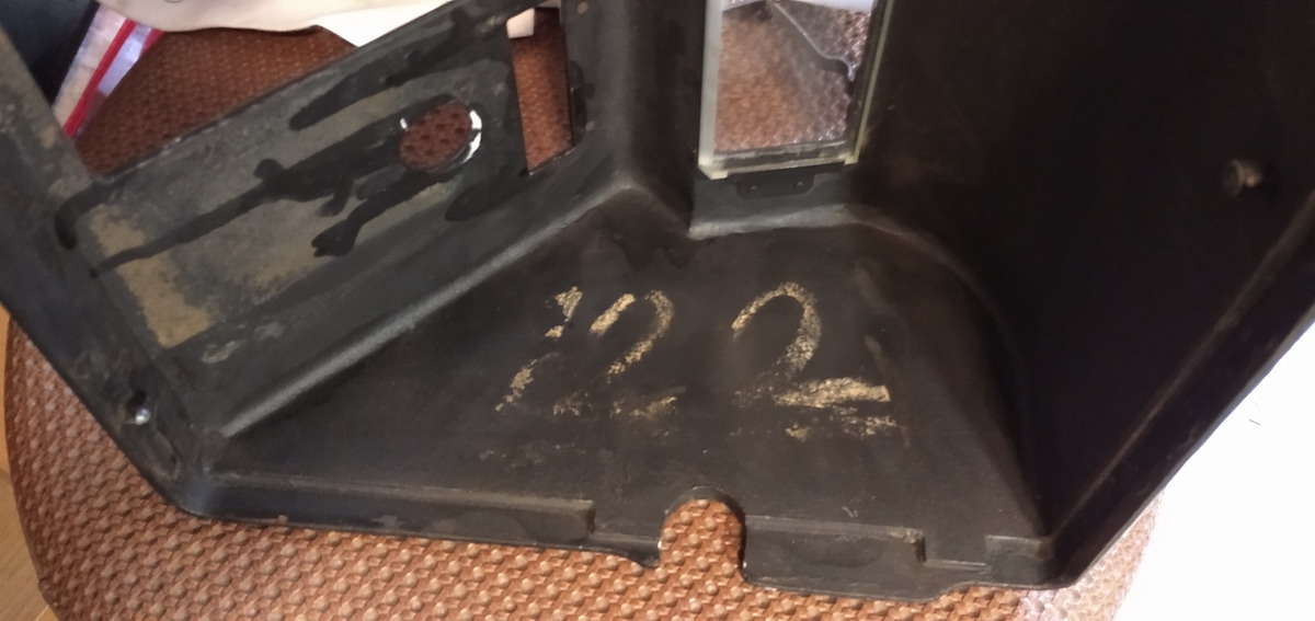
This machine came out of the collection of Thomas Russo, and was purchased by the Arithmeum in a large lot of uninteresting calculators, put up on ebay by a certain well-known auction house in Köln. It is a shame they sold what was pretty much the most interesting machine in Russo’s collection, potentially worth thousands of euros all by itself, by this kind of an arrangement. But oh well - the Arithmeum got really lucky here. Vigilance pays. They already had a second Ensign, an 97 model (9 keyboard rows, 7 counter positions), serial number 507. This one has 5 keyboard rows and 4 counter positions, hence the model number, 54. Its serial number is 220. I am aware of one other example in the MAH/Smithsonian in Washington DC, (which they call a “model 90”, but is also a model 97) with unknown serial number, and a machine that was at some point bought by Bob Otnes in quite derelict condition. I do not know what happened to that machine after his passing. If anyone ever comes across another one, please let me know, I would be very interested in purchasing it.
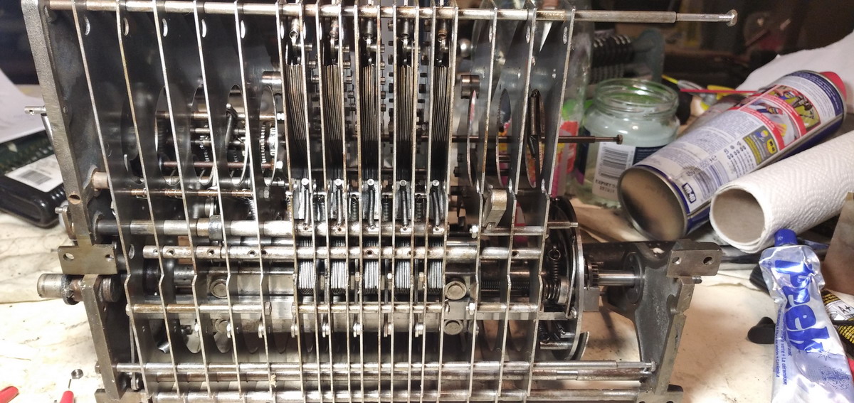
It came in rather derelict condition (but not as bad as the Otnes machine ...), and calcusaur.us was asked to look at it and if possible restore it to working condition. I was very much looking forward to the challenge, because by what I know of the Ensign calculator, it a an entirely different beast from anything else that ever was on the market. Emory S. Ensign was an inventor who decided to wage war on calculators such as the Comptometer, in which the keystrokes of a “1” and a “9” had different depth and required different effort to push. This would have to be the single discerning feature of his machine, that all keystrokes would require the same amount of effort and would be of the same depth. As he repeats over and over again in his patents. He does sound like a tiresome character ... :)
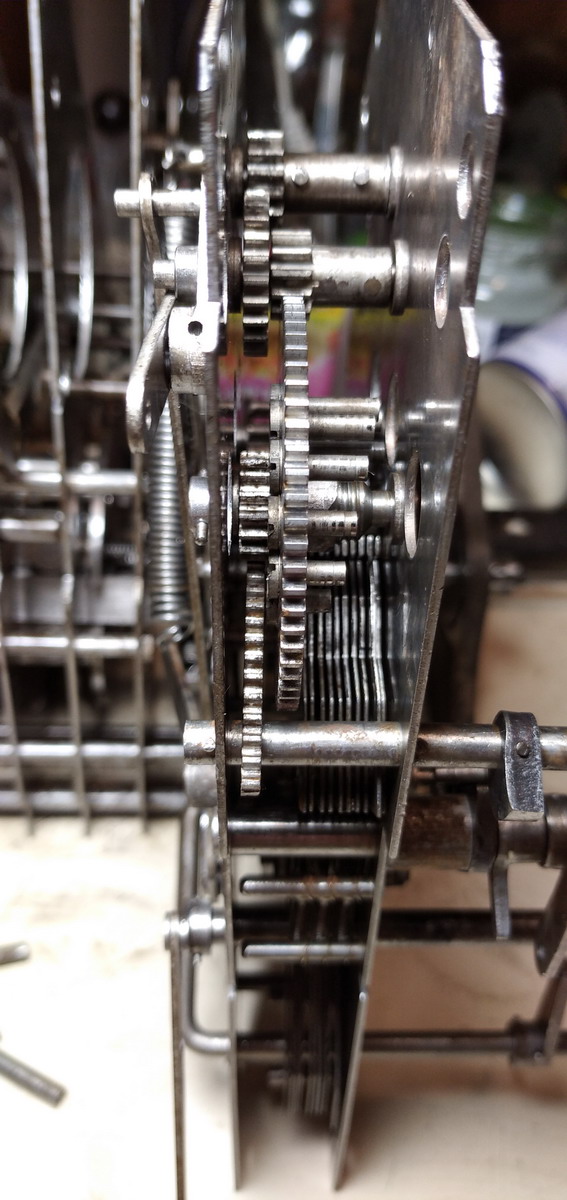
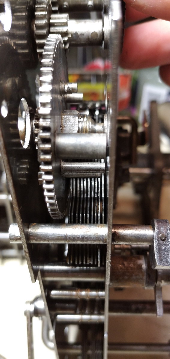
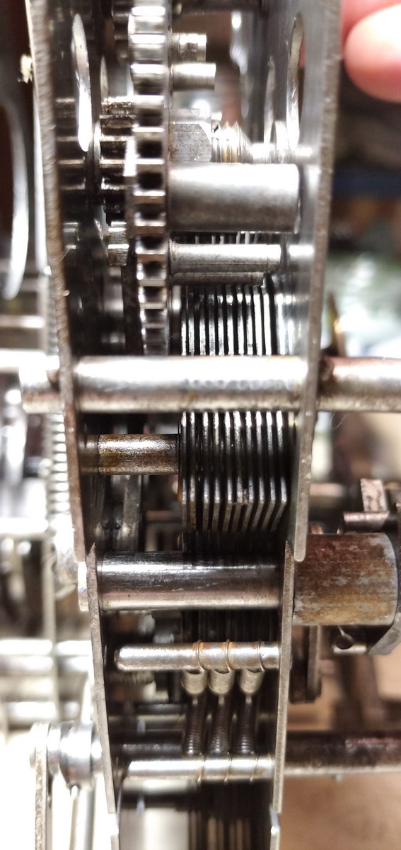
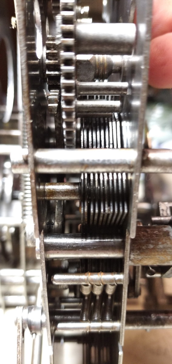
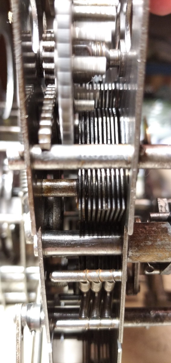
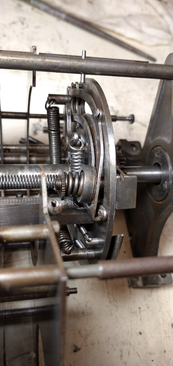
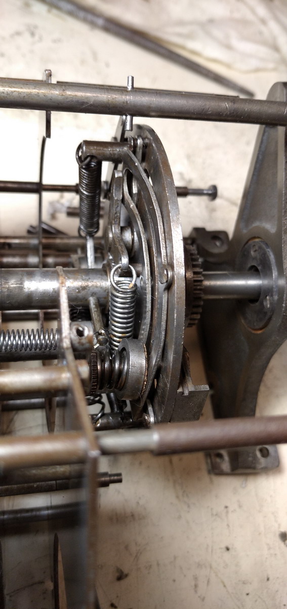
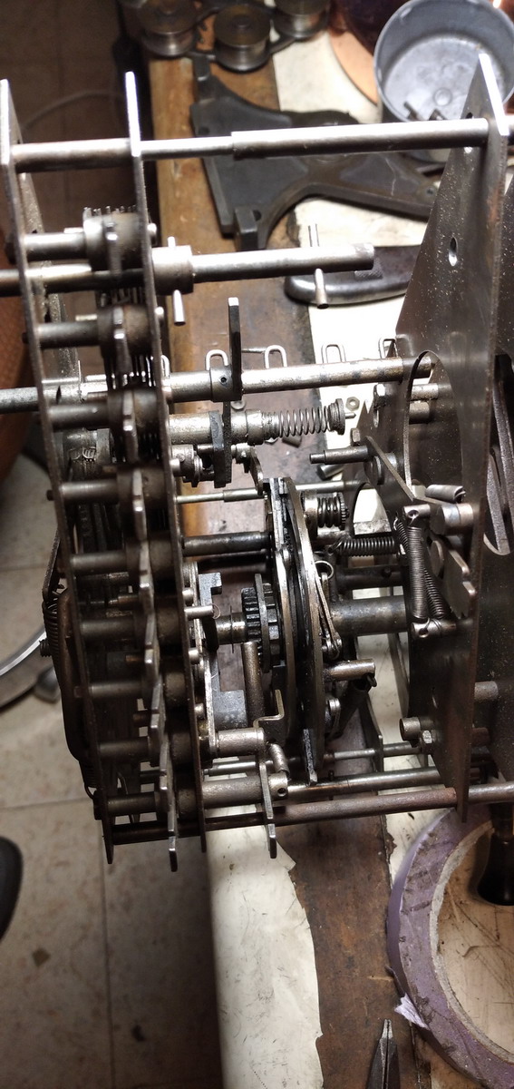
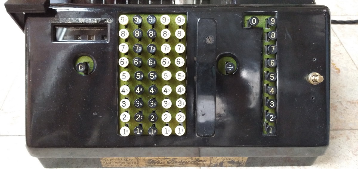
He managed to achieve this by completely reversing the architecture of the calculating machine - whereas normally the actuators rotate (together as one cylinder in a pinwheel machine, or as a set of stepped drums in a Thomas type machine) and the result register stays stationary and can move left to right, in Ensign’s design, the keyboard is stationary, and presents a metal circle section with cutouts, that is the actuator, to the result wheels. These are shaped like old-time riverboat paddles, and move by the actuators arranged in a kind of drum, that rotates - so stationalry actuators, and a rotating register (or “meter” as Ensign calls it).
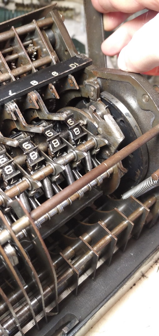
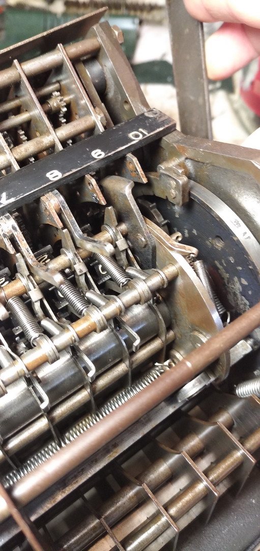
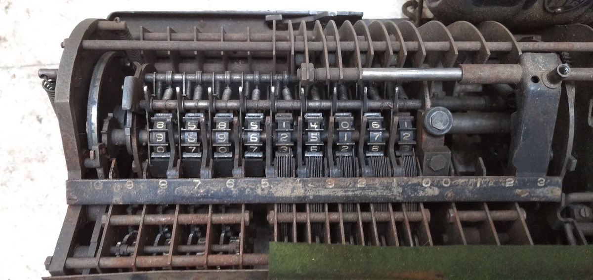
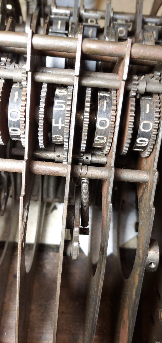
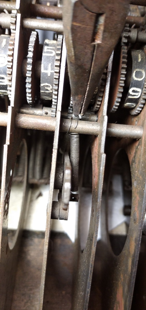
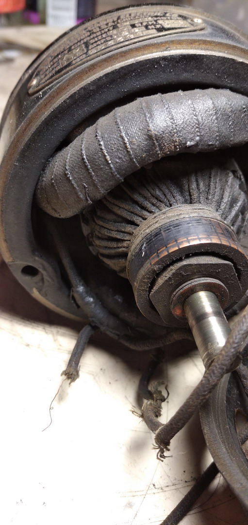
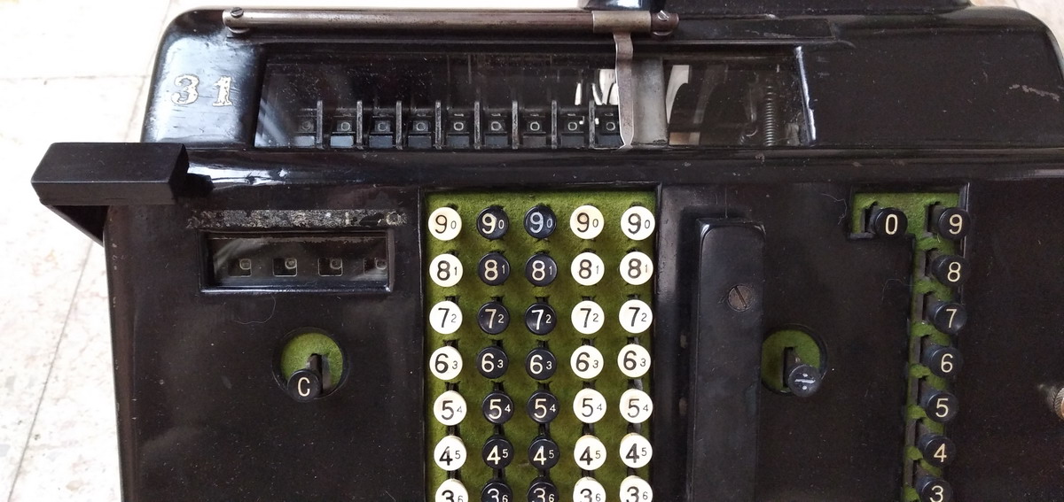
In this picture you can see the 1,3,5 and 7 key pressed in succession:
And this is a video of the machine operating:
The counter register is “normal” in the sense that it sits immobile on the left side of the machine, but if you read through the patents, you realize that poor Emory S. Ensign ran into a spot of trouble - if your counter register is fixed, and you move the result register past the keyboard, and it is actually the result register that operates the counter, then the counter wheels are actuated in reverse order, and your multiplier has to be read from right to left. After being quite blasé about this for a patent or three, he finally realised that this would not be acceptable to the average customer, and he designed a system with intermediate shafts that transfers the movement of the counter gear that is actuated to its mirrored equivalent in the actual register. That system is included in this machine, so the multiplier at least reads correctly.
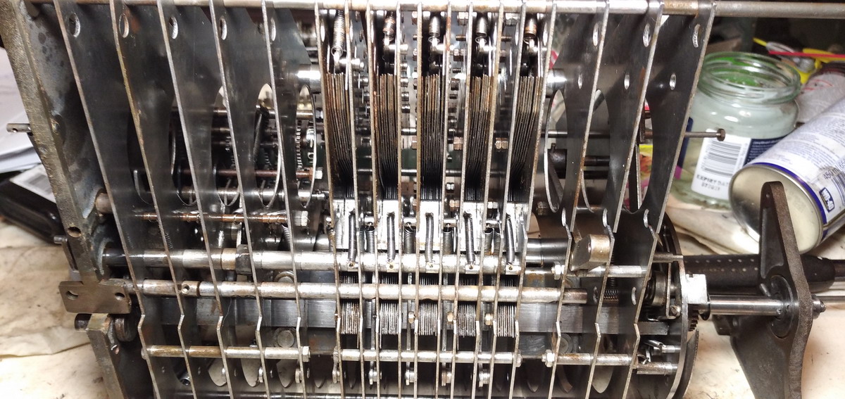
Other interesting technical solutions involve rigorous systems to prevent accidental overrotation - every wheel in every register is only released for the duration of time it takes to be operated, and then immediately positively locked again. A smart idea, but quite involved in its execution.
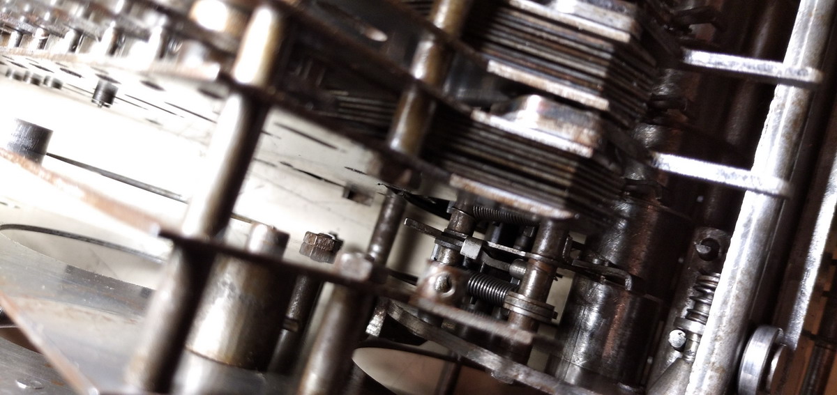
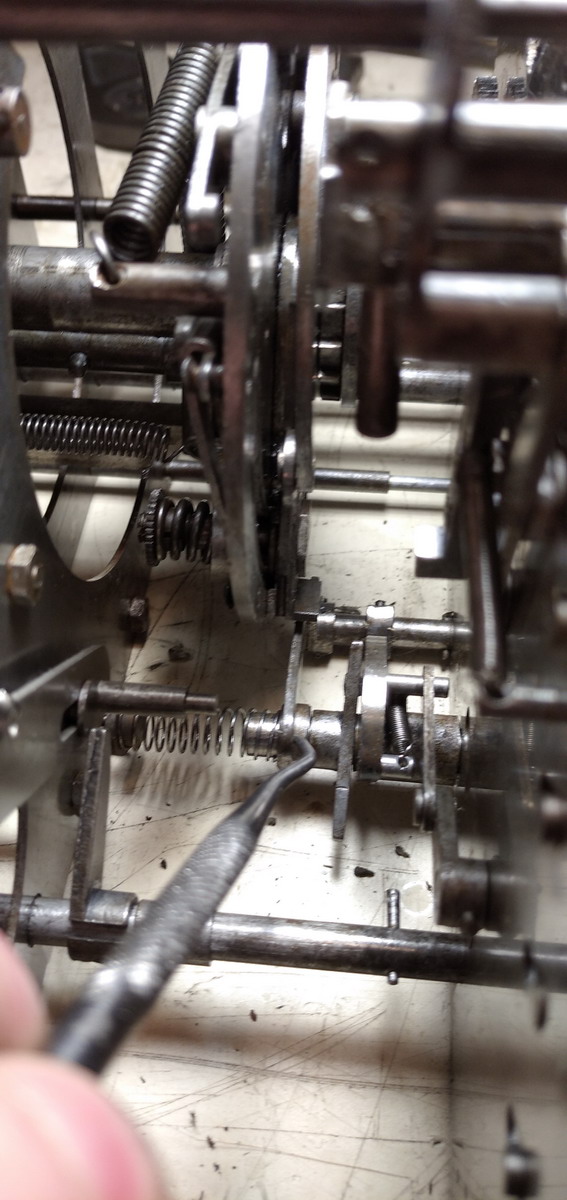
Another noteworthy innovation is the tens’ carry. Obviously this needs to be incorporated in the rotating drum which contains the register (and which Ensign in his patents calls “the meter” ). It is a system that is not unlike that used in the Comptometer - since the numeral wheels are shaped like paddle wheels, the “teeth” are sticking out on either side, and that makes it easy to operate on them for tens’ carry with spring-loaded levers that are inbetween two of them. A wheel rotating from 9 to 0 will activate the lever to set up the carry, it is however held in place by a “foot” impinging on a sector next to the circle sections that are doing the counting, and is kept in place until all numbers in the keyboard have been transfered to the result register. At that point the levers are released and carries are effected. If a carry leads to a follow-on carry, this happens immediately. On the last part of the rotation of the drum, a special extention to these levers hits an obstruction at the bottom of the machine, which re-cocks the carry levers, ready for the next rotation. This is nigh on impossible to catch in pictures, as the machine is built so densely that nothing at all is visible on a stationary picture.
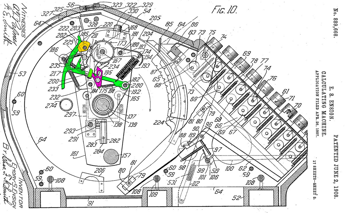
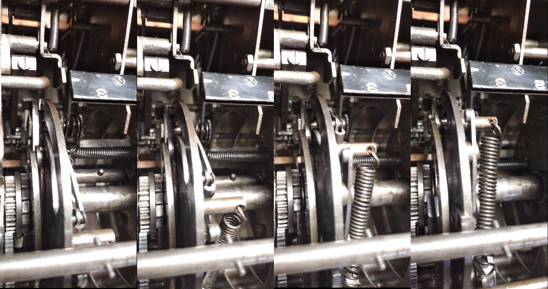
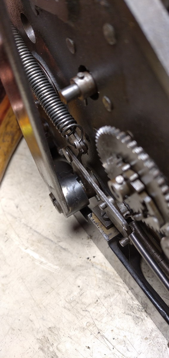
I will make an attempt with the relevant pictures from the 1908 US Patent nr 889,668, of which the tens carry system corresponds with what is in this machine. The carry-up hammer (192) is shown in bright green, as an individual part in Fig. 32 and 33.
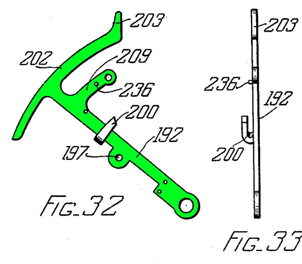
It pivots on one of the through rods (182) through the result register. They are held in a forward position by the large spiral spring 193, which is attached to the back of the support carrying the black metal plates shielding the bottom half of the numeral wheels when looking at the register. The carry-up hammers are guided by the yellow parts 220, also on a tie rod through the register. Pinned to the carry-up hammer is the carry-up pawl 175 (in purple), in such a way that it can tilt freely. It’s position is secured against the curved side-arm of the hammer by a smaller spring 198. All of this is visible in Fig 10.
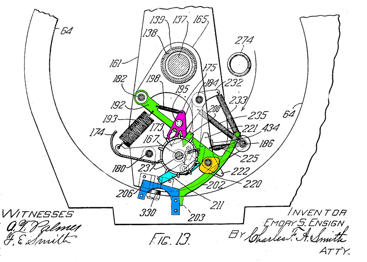
The entire progress of a carry is shown in figure 11, 12 and 13 below.
The point of the purple part can strike the projecting “paddle” of the numeral wheel to its left. As the carry-up hammer, shown in its cocked position in Fig. 10 and 11, moves through its full path, the purple pawl will push the numeral wheel to the left one-tenth of a revolution, effecting the carry, and the curved hook will prevent its overrotation, as can be seen in Fig. 13. Fig 12 shows how the nose 203 of the carry-up hammer is in contact with the “segmental runway” 204 (orange) which prevents it from coming fully forward until the numeral wheels are completely past the actuators. At that point, the runway ends, and the carry hammers spring forward. After operating, they carry-up hammers are recocked by “recocking plate” 206 (Fig 13, blue), which tilts it back into its “armed” position. The armed position is retained by the “hammer-cocking retaining pawl” (211, Fig 11 and 12, cyan), which has a hook bent to the right, which engages with a slot 178 in the basic structural plate 165 (Fig 24) in the carriage.
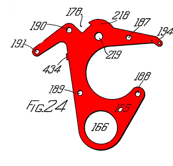
The outline of this is traced in red on Fig. 10, and indicated in red on 11, 12 and 13, and you can see the hook on the cyan part 211 sitting in this slot 178 in the red-traced 165 in Fig. 11
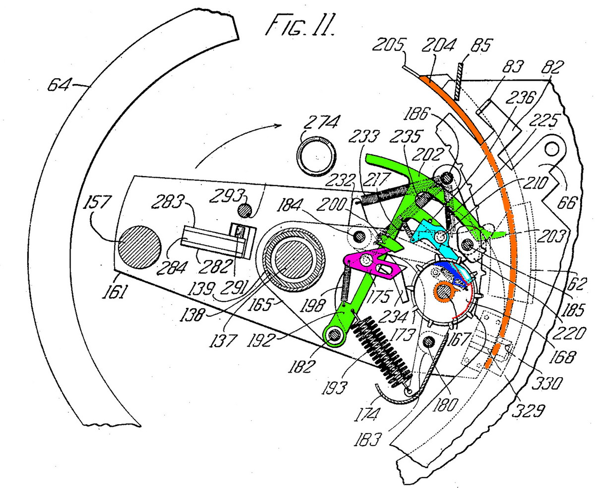
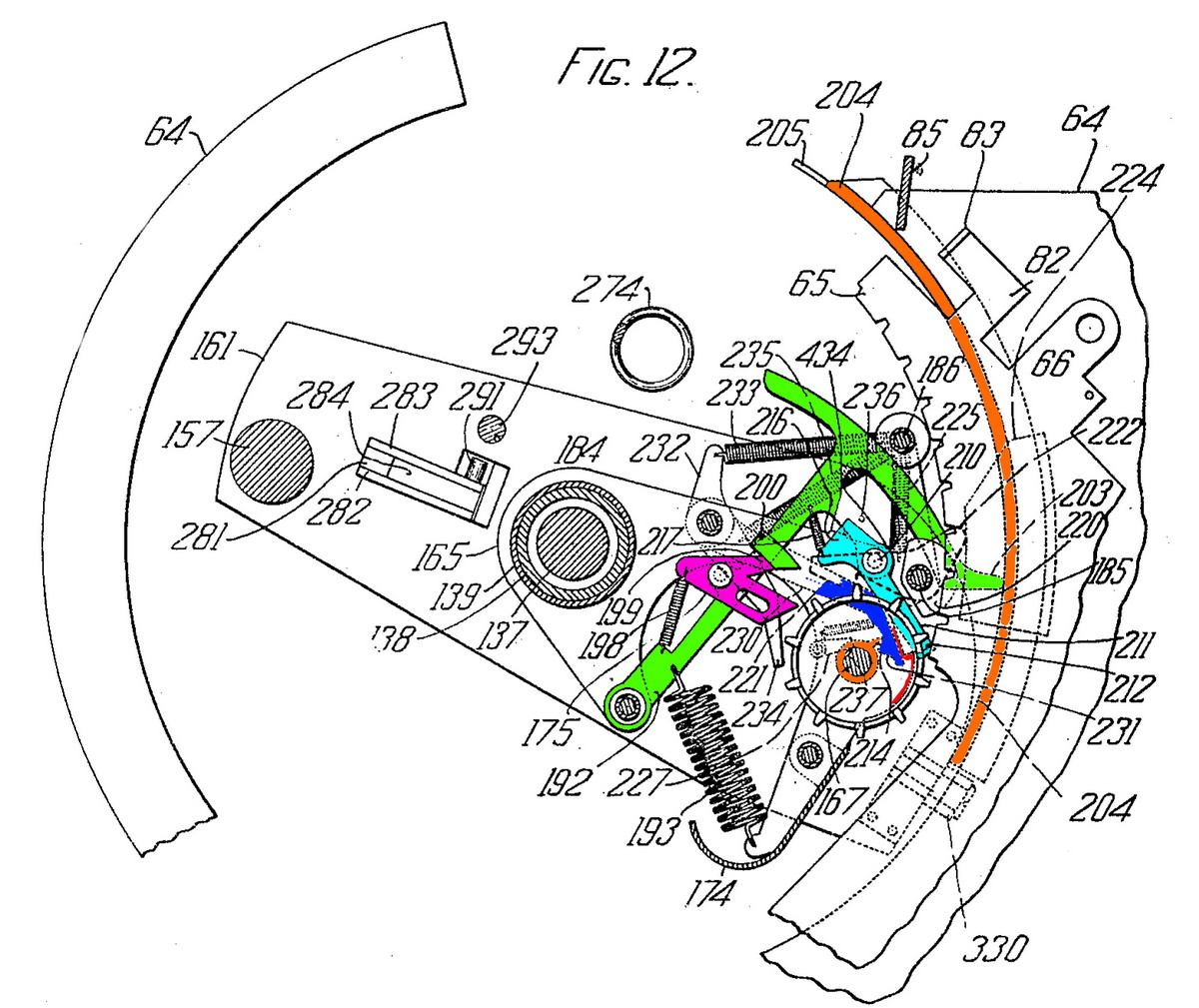
Now on to how all of this is operated by the numeral wheels - each numeral wheel has on the right side a cam with a tooth, shown in orange. This cam, when the wheel rotates from 9 to 0, pushes against a pawl 230 (dark blue). Refer to Figure 11. This in turn pushes the hook of 211 (cyan) out of the slot in 165 (red). In Fig 12 this has just happened, and it will allow the ten’s carry hammer to shoot forward as soon as it is no longer retained by the segmental runway (in orange) (Fig 13), pushing the next higher numeral wheel on the left one position forward. If a carryover through the entire register has to happen, this sets up a chain reaction - every wheel rotating past 9 trips the blue pawl, unhooks the cyan retainer, the carry hammer shoots forward, and effects the carry to the next wheel. Since the carriage has already rotated past the “segmental runway” at the stage where the first carry happens, the process then happens simultaneously for all affected numeral wheels.
However, in a video, the mechanism becomes more or less clear. The moving parts are the cyan “hammer-cocking pawls” that are pushed out of their slots and are then carried along with the tens’ carry hammers as they reach the end of the “segmental runway”.
This is a video of the tens’ carry of the machine:
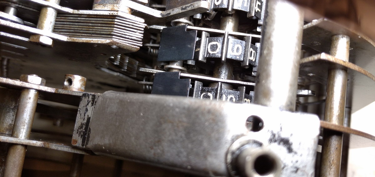
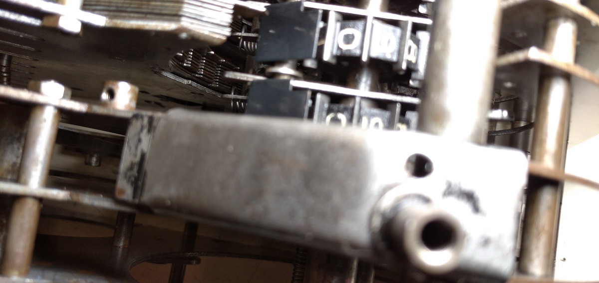
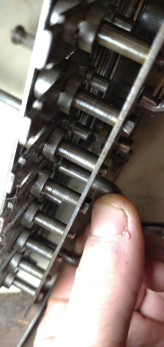
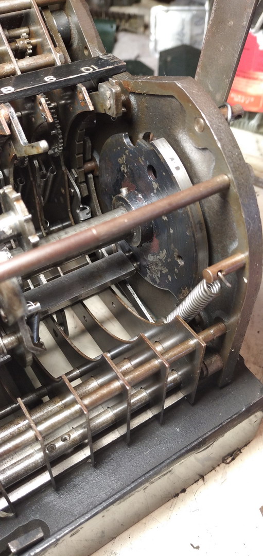
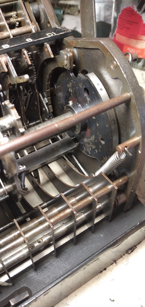
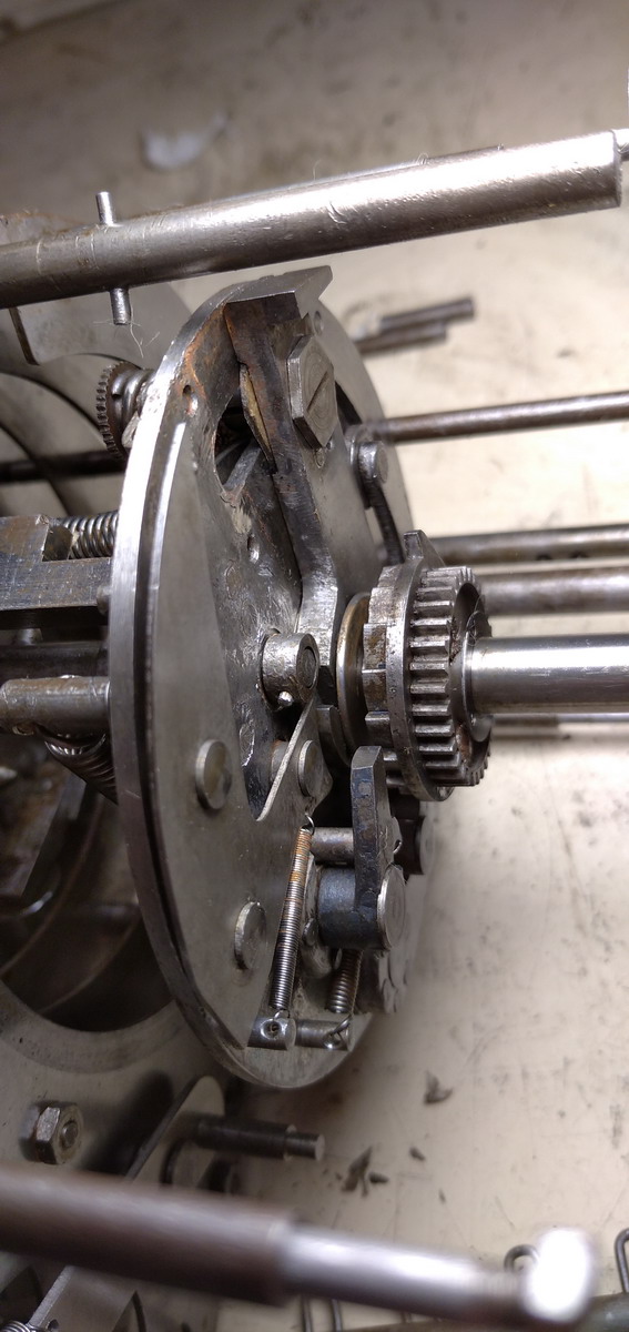
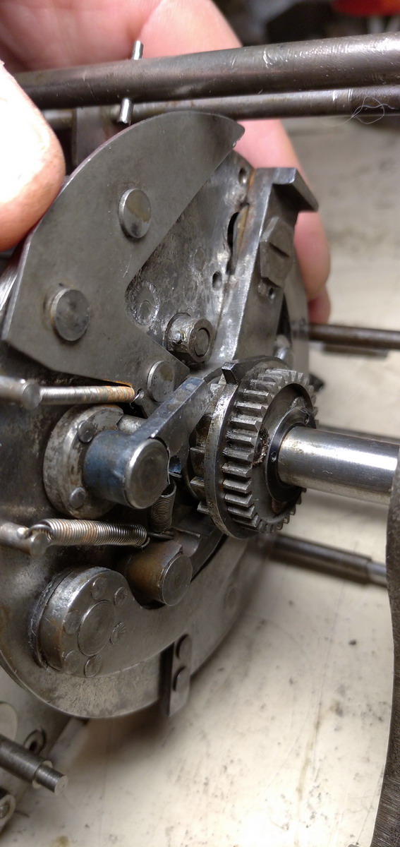
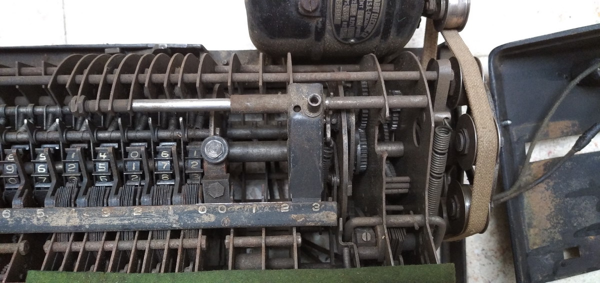
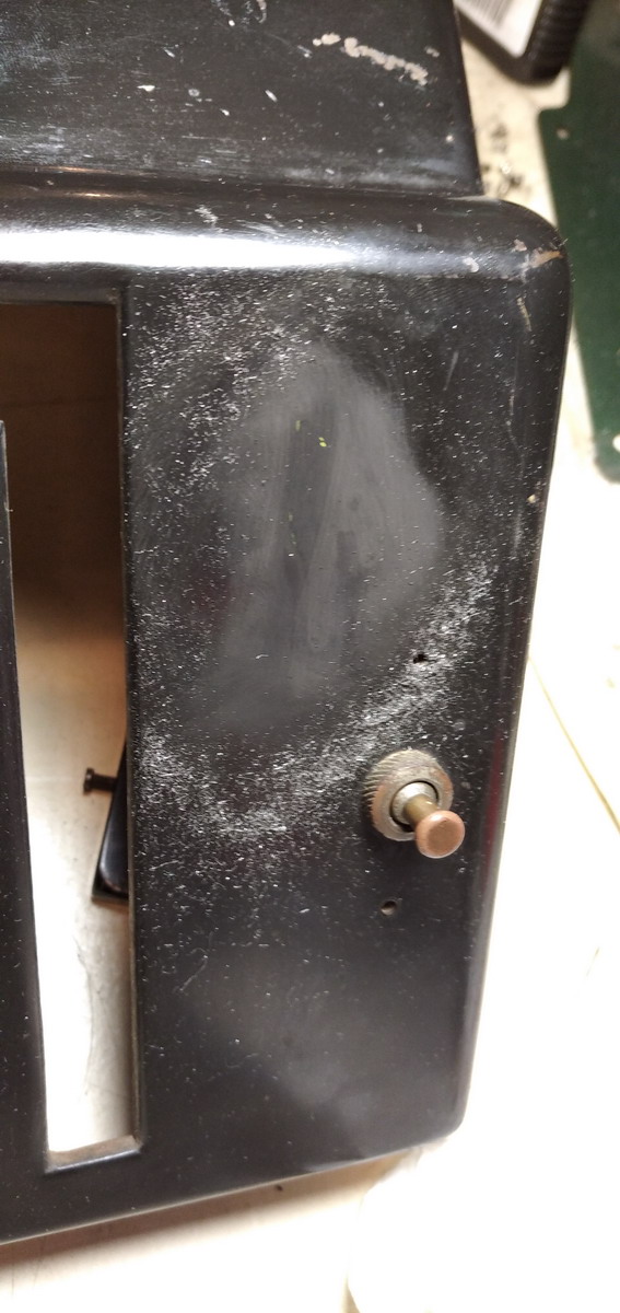
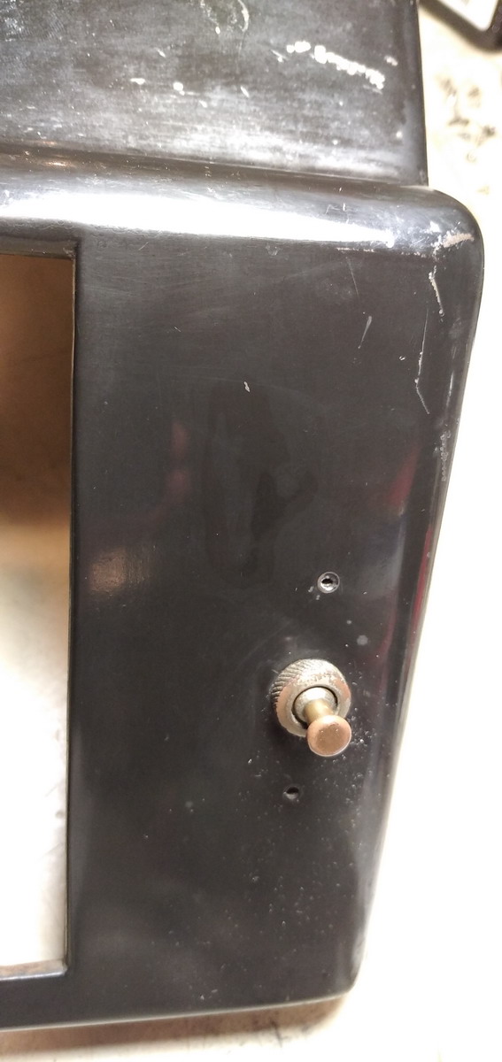
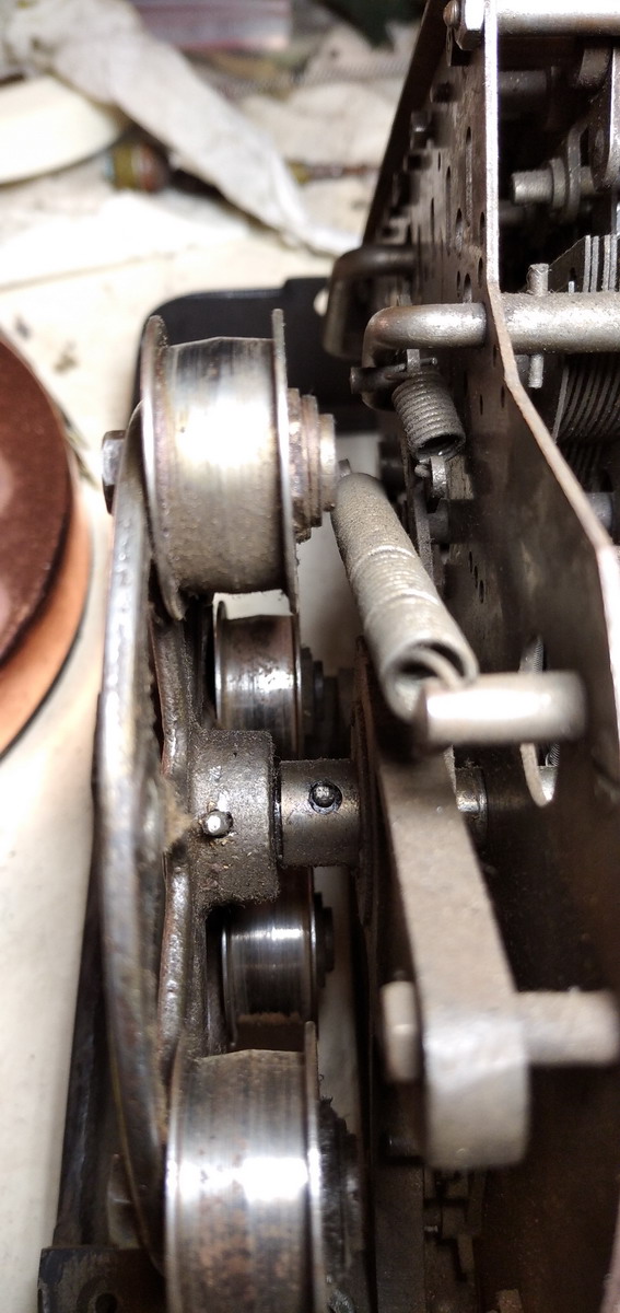
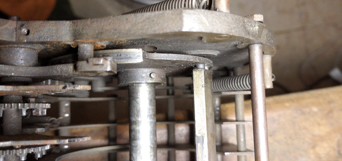
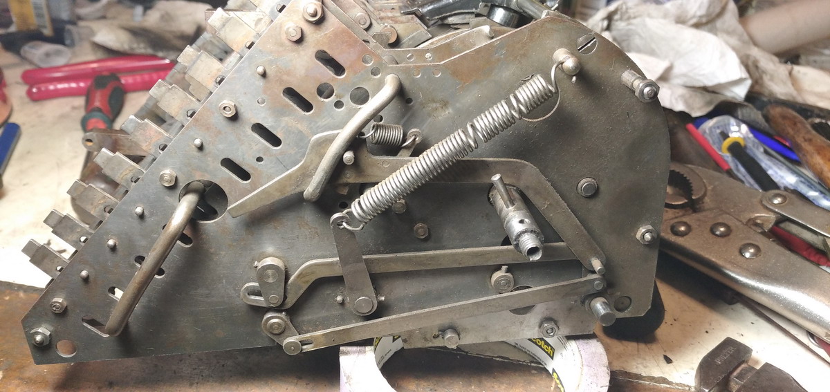
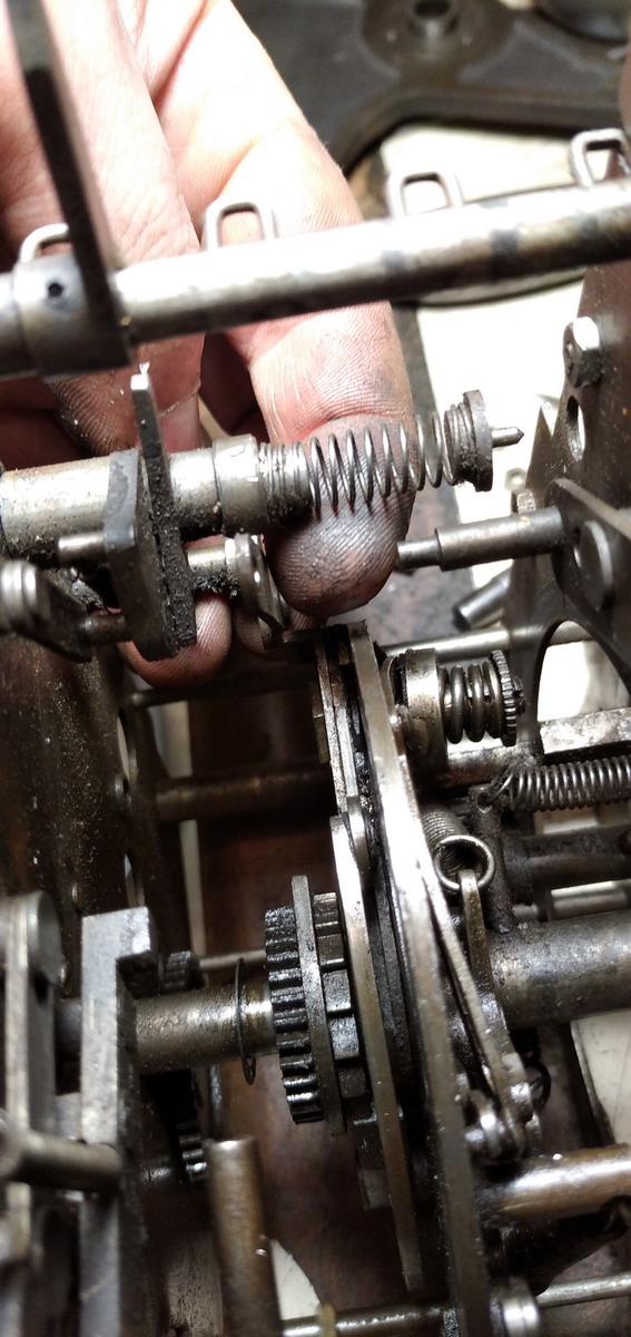
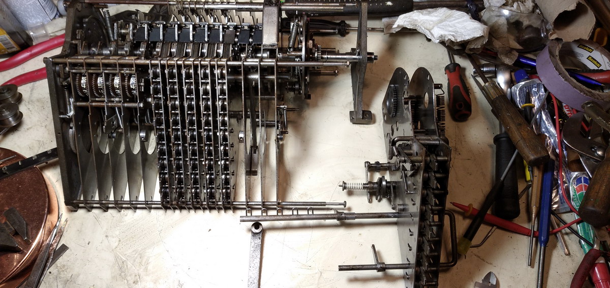
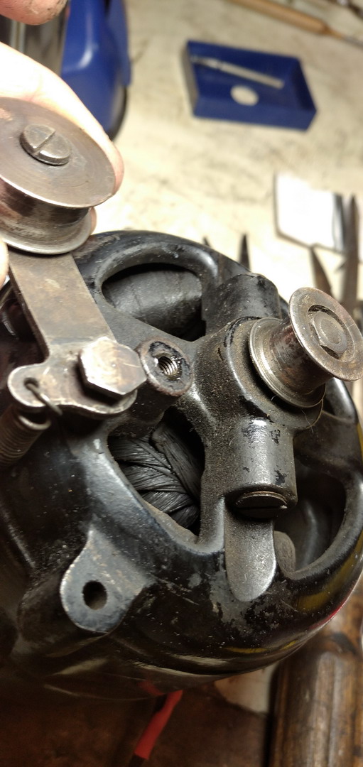
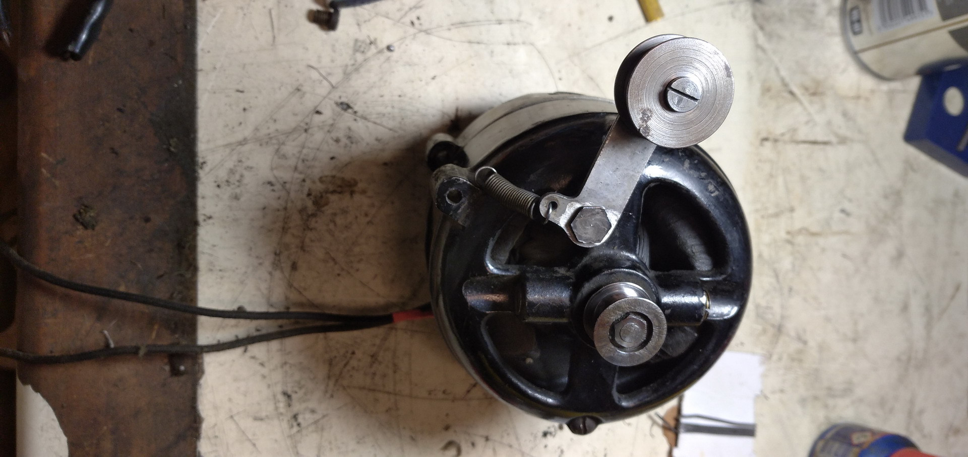
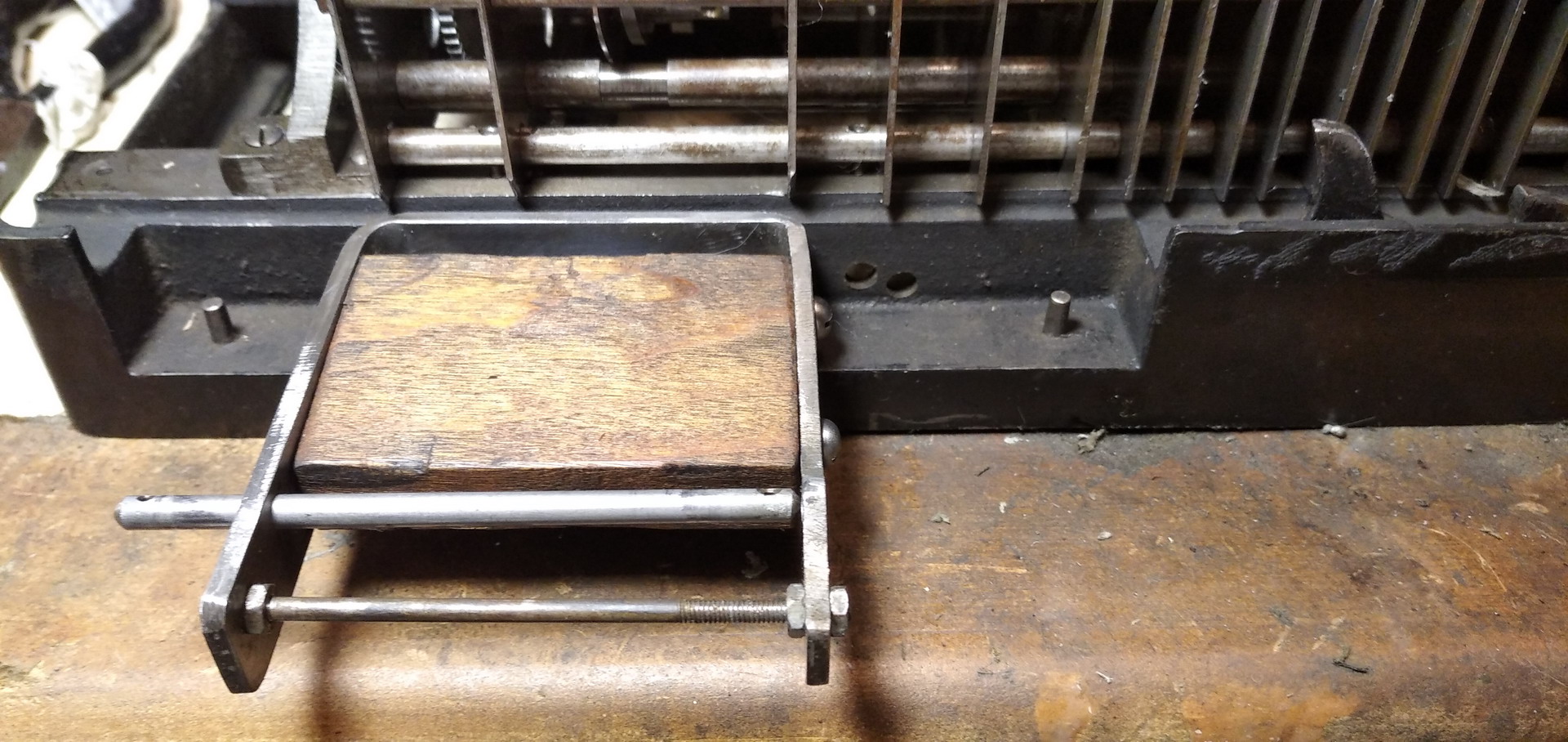
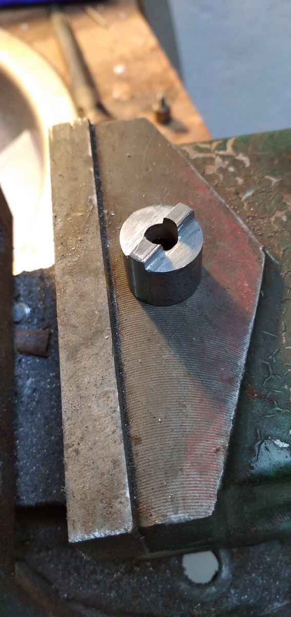
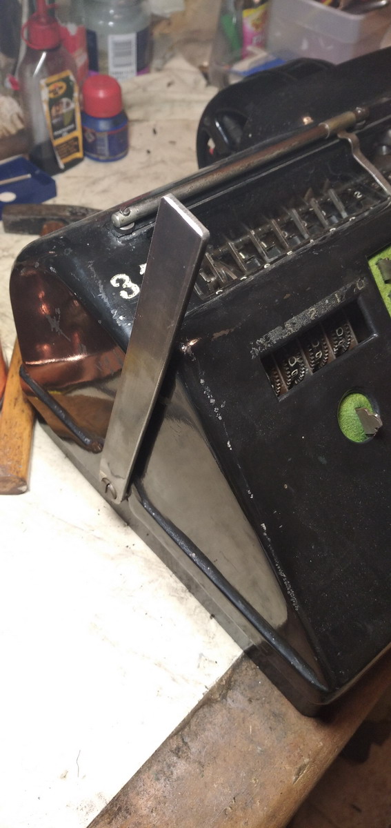
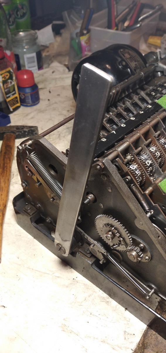
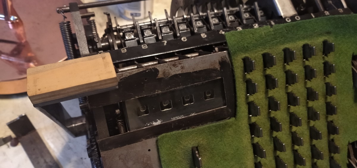
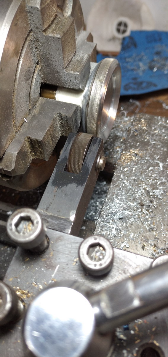
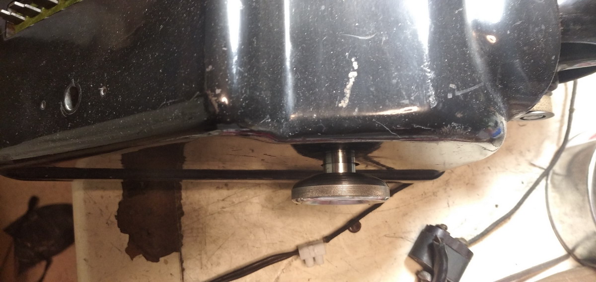
There’s also the multiplication to deal with. That involves a few other systems that need explaining. First off, the drum carriage is slidable along an axle to be able to take up various positions with respect to the keyboard. It can be shifted left with a hand lever when the drum is in its rest position. it has a kind of snap-latch action once it reaches the next position. This is determined by a bar with pins sticking out. You can see this mechanism in the bottom right corner of the following picture:
The bar can rock on operating the “0” key in the multiplier keyboard, which then releases the carriage, which is spring loaded, and moves one position to the right. This mechanism also operates at the end of a multiplication cycle, shifting the carriage ready for the next multiplier digit.
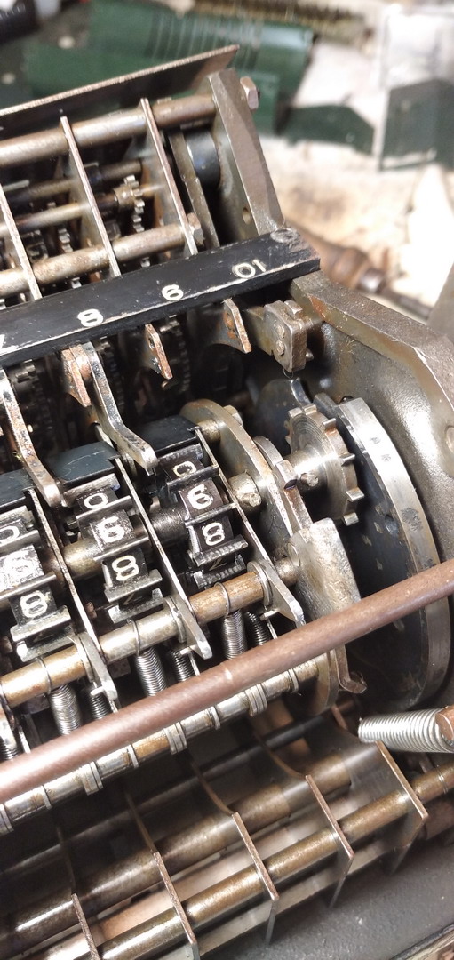
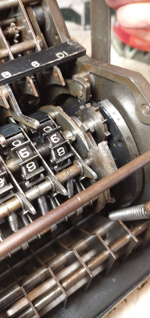
The multiplier digits are selected with a similar set of plates as the main keyboard (remember, having identical keystrokes everywhere in the machine was very important to Emory!), but they don’t have teeth for actuating the “paddlewheels” counters, just one protrusion at their bottom. Since the plates are all next to each other, with “1” on the right, and “9” on the left, Ensign devised a gear train to wind up a spring loaded gear for about 1/12th of a rotation every time the register drum rotates. This large, slow rotating gear has pins sticking out of its side that grow longer progressively and stepwise, so that for example after six rotations of the drum, the gear has reached a position where the pin 6 is now long enough to push the plate for the 6 key back up, which puts the stop mechanism in the path of the register drum, which then stops and locks it at the end of turn number six. Since plate 8 is further to the left, the gear needs to carry on rotating, and only pin 8 is long enough to throw the 8 on the multiplier keyboard out of engagement, which again stops the register once it completes its turn, and as soon as it does, also a pawl is uncoupled from the drive of the pinned gear, and it returns to its original position under spring pressure.
Here is plate 8 being pushed:
The wheel with its pins for clearing being rotated towards it ...
...pushing the plate back, and engaging the stop mechanism for the drum
...and then being released and returning under spring pressure
Pushing the “Add” bar on the keyboard has the same effect as pushing the “1” multiplier key. The bar operates a finger that actually pushes the “1” multiplier part internally in the machine.
Four more systems need explaining: the clearing, of the keyboard and the registers, the “division” button, and the drive of the machine.
Clearing is effected with a lever on the left side of the machine, which was missing here. Who knows what had been going on there, because the entire counter as well as the clearing mechanism had been completely screwed up...
Now - to the basics. Every paddle wheel and counter numeral wheel has a pawl on the inside. The shaft they sit on has a groove with one sharp edge. If the shaft rotates a full turn, at some point the sharp edge of the groove is going to pass the pawl on the numeral wheel, the pawl is going to fall in, and is going to drag the wheel along in its rotation until the shaft has made a complete turn, and all numeral wheels are at zero. They can only continue rotating in the same direction, because the pawl blocks them in the other direction. This is exclusively an adding machine, any subtraction has to be done with complements.
Now on to how these shafts are rotating. Pulling the handle on the left side of the machine has three distinct effects: first of all, in the very first few centimeters of its rotation, it will unlock the spring-loaded keyboard. If desired, the bar can then be let go, and that is all that will happen. If it is pulled through though, it will start a rotation cycle of the machine (see below for how that happens). The keyboard has been cleared, and so nothing will be added to the register. A circle section with cutouts is pushed forward by the handle.
If the register drum is in its leftmost position, the circle section is in the path of the star wheel on the register axle, rotating it through and pulling all the wheels to 9, except for the rightmost one, which is pulled through to 0.
The tens’ carry mechanism then does the rest and resets the whole register to 0. The vulnerability here is that if the star wheel on the axle is pushed to an incorrect position somehow, the clearing won’t work, and the register will go to some other number than 0. Clearing the result register can be avoided by not placing the register drum in the leftmost position, because then the star wheel for the register shaft will not engage anything and the register value will stay as it was.
Pulling the clearing lever through even further will wind up a spring loaded gear that, via a gear train, rotates the shaft for the intermediate gears for the counter, which are similarly provided with a pawl to fall into the slot in the axle. Releasing the lever will then by spring pressure rotate the axle back around, and reset the counter register to zero.
The last item to affect the operation of the clearing is the “C” button for the keyboard. If this is engaged, the clearing lever will release the keyboard for about half of its travel, so that the main register can be cleared (if there would be a value fully set in the keyboard, it would be added to the register, so this should not happen). However, when the lever is released, the keys are pulled back in so the number that was set stays also stays in the keyboard.
In that way, one lever is enough to provide independent clearing for the keyboard as well as either or both of the counter and result registers.
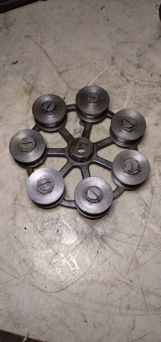
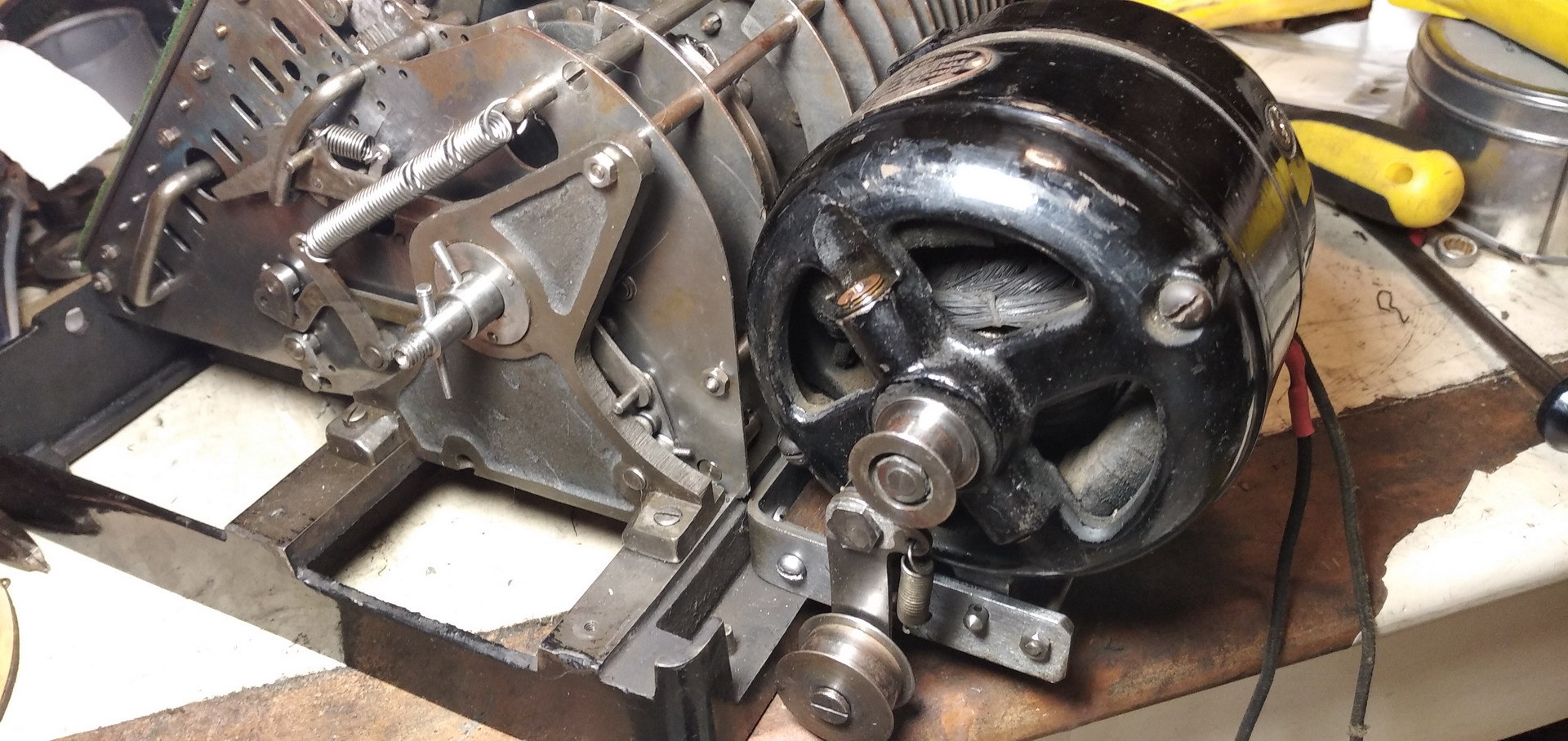
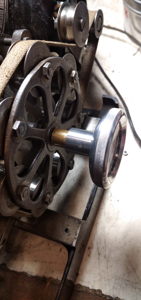
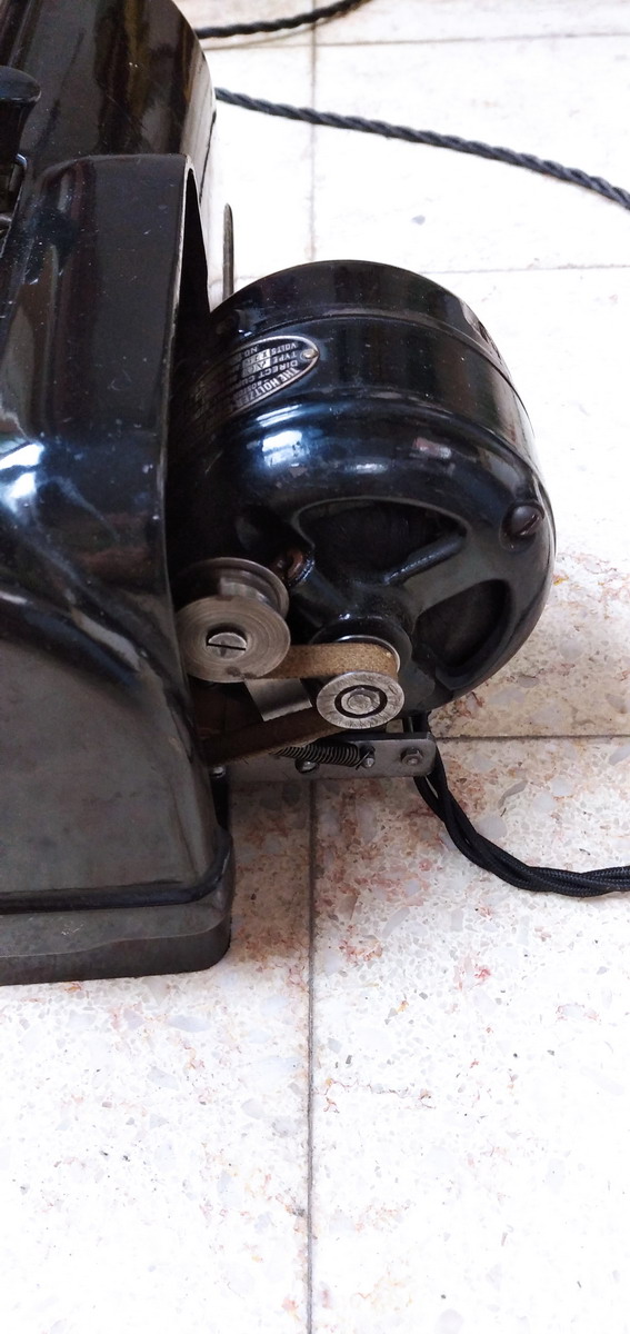
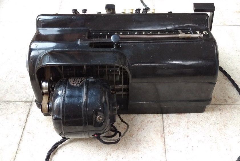
Now for the machine drive. This is actually quite artfully concocted as well. On the righthand side of the axle is a large cast iron wheel with seven auxiliary wheels on its circumference. They are connected to the 110V DC shunt motor by a cotton belt.
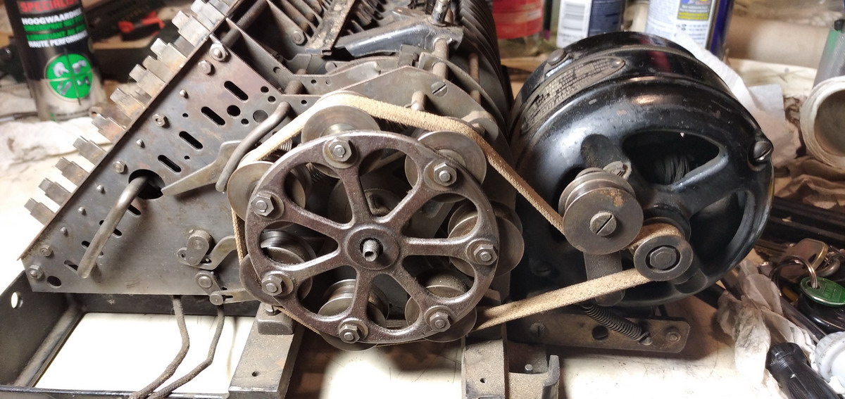
And here is where it gets interesting - five of the auxiliary wheels are free to rotate on their axles, and two of them are firmly fixed to the cast iron frame of the main wheel. With the machine in the rest position, the cotton belt only touches the wheels that are free to rotate, and hence the machine idles. A soon as a button on the multiplier (or the sum bar) is pushed, the drum is unlocked and rotates by a few degrees under spring pressure. This is enough to make the cotton drive belt grab onto the first of the non-moving auxiliary wheels and pull the drum around. If it is not stopped in its tracks by the spring-loaded lock at the end of its rotation, it carries enough momentum to get carried past the “dead” idling point and the machine continues to rotate. When the requisite number of rotations has been made, the multiplier key pops back up, and the stop is put in the path of the drum. It is hit by a spring-loaded contraption which slows the drum down gradually, until it locks in place in a position where the drive band just misses those two fixed auxiliary wheels, and the machine idles.
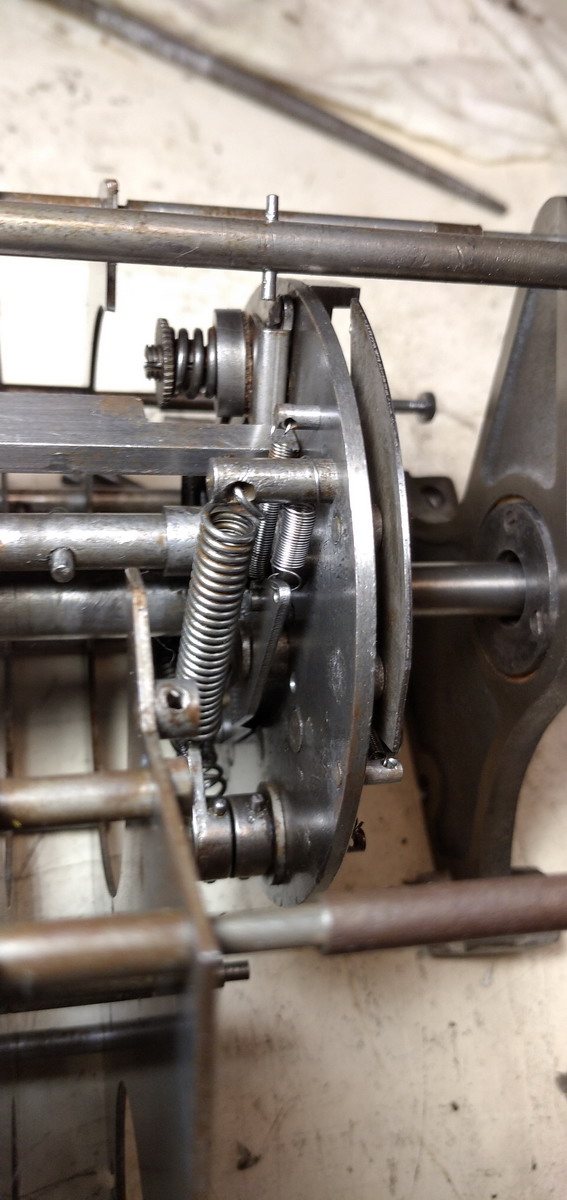
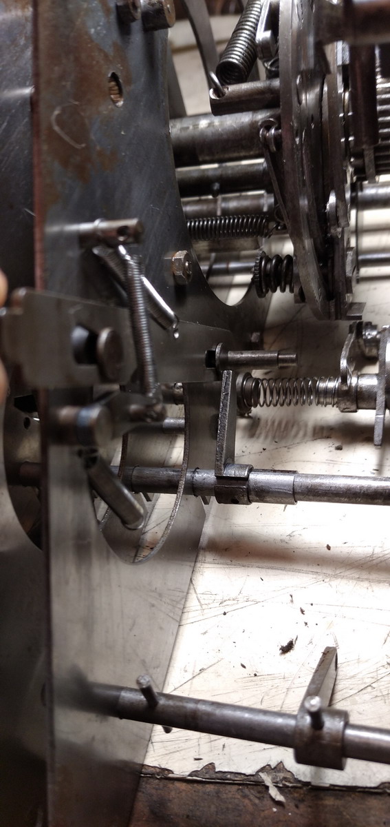
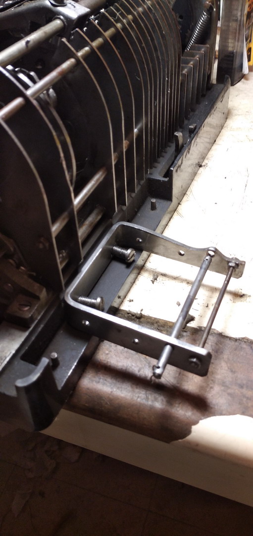
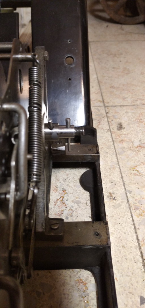
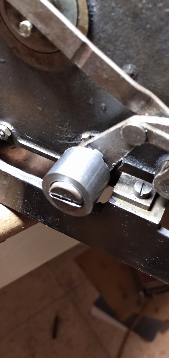
The spring loaded stopping mechanism can be seen in action in this picture:
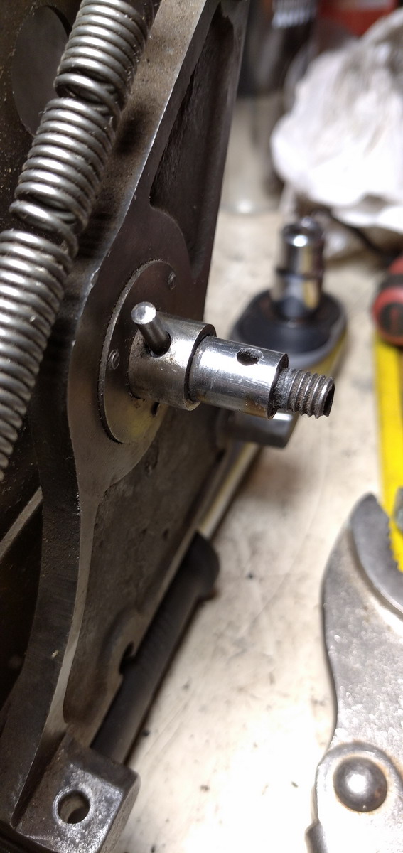
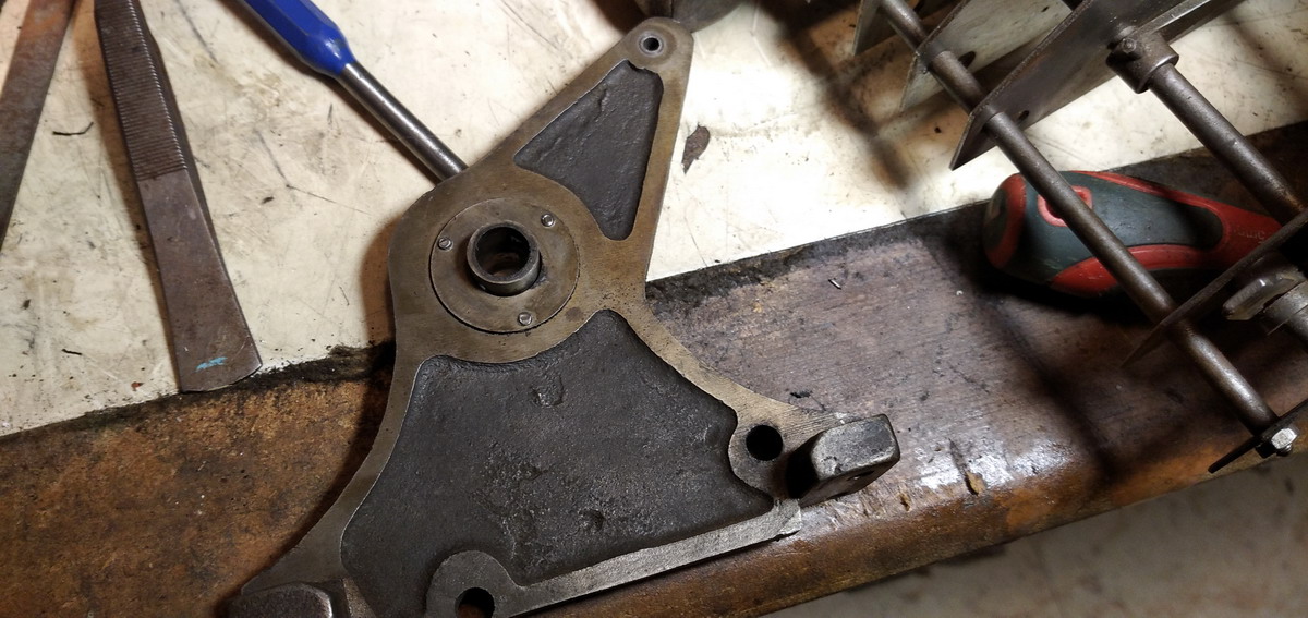
And finally, the division button is the last piece of the mechanism that needs explaining - all that is does is to rotate an operating pawl on a shaft, so that when it is pushed in, it touches this plate as the carriage returns to its rest position:
When the plate is pushed in, the spring loaded mechanism that is wound up as the drum is rotating during a multiplication is kept from operating the bar that causes the carriage to shift at the end of a multiplication cycle. So with the division button pressed in, no carriage shift.
So now, what needed to be done to the machine ?
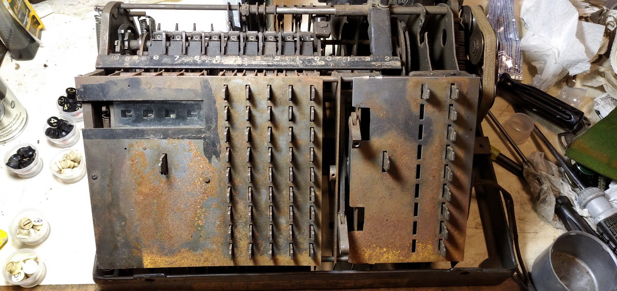
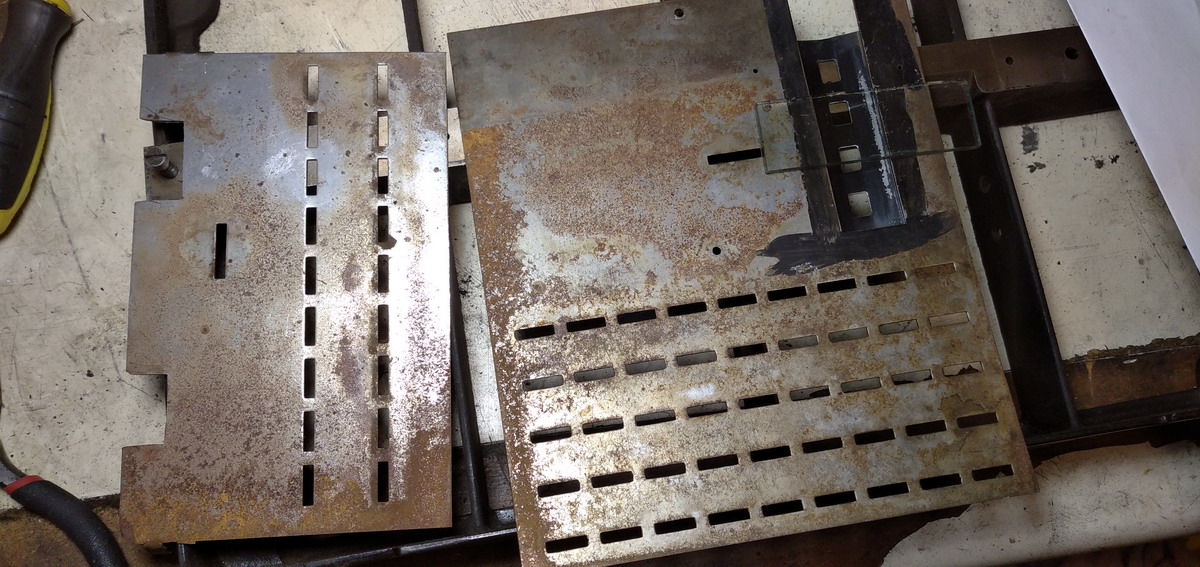
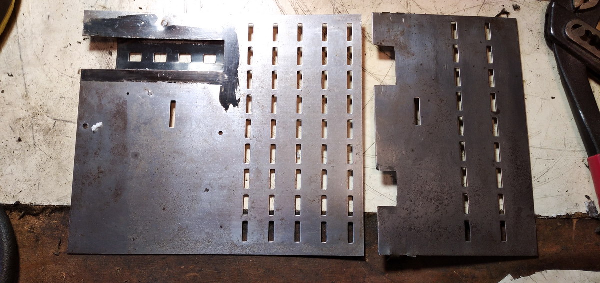
A few problems emerged, but the first step was establishing that it was absolutely disgustingly filthy and rusty, and something needed to be done about that.
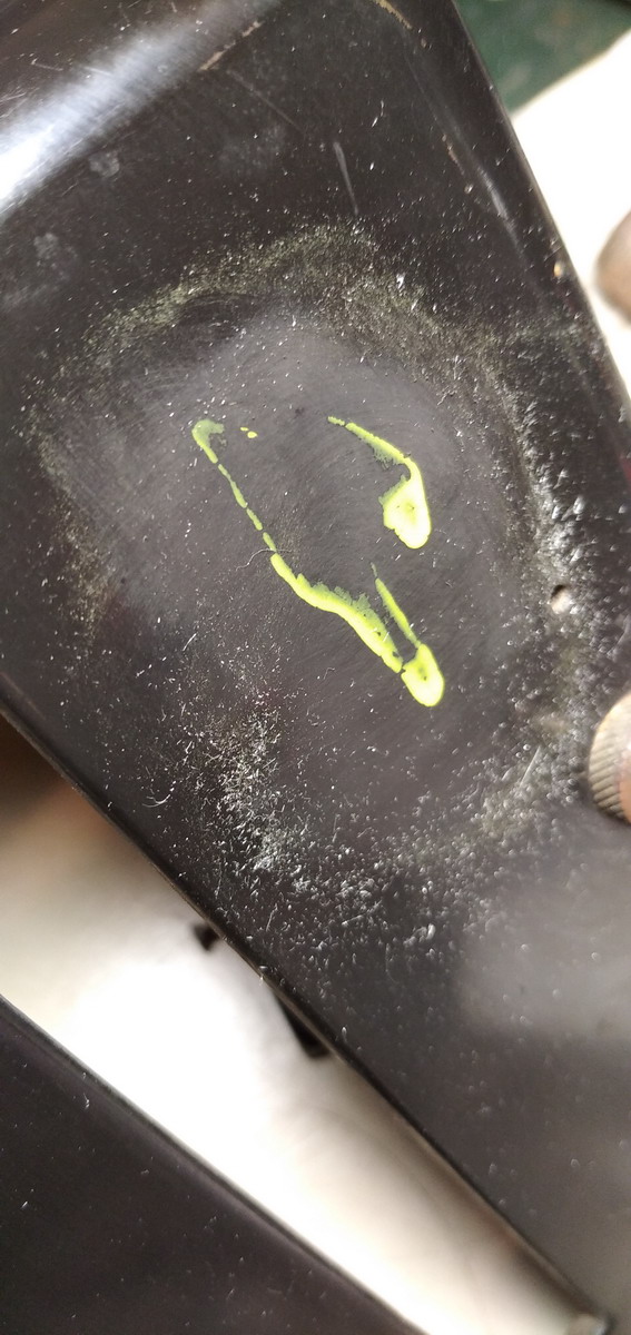
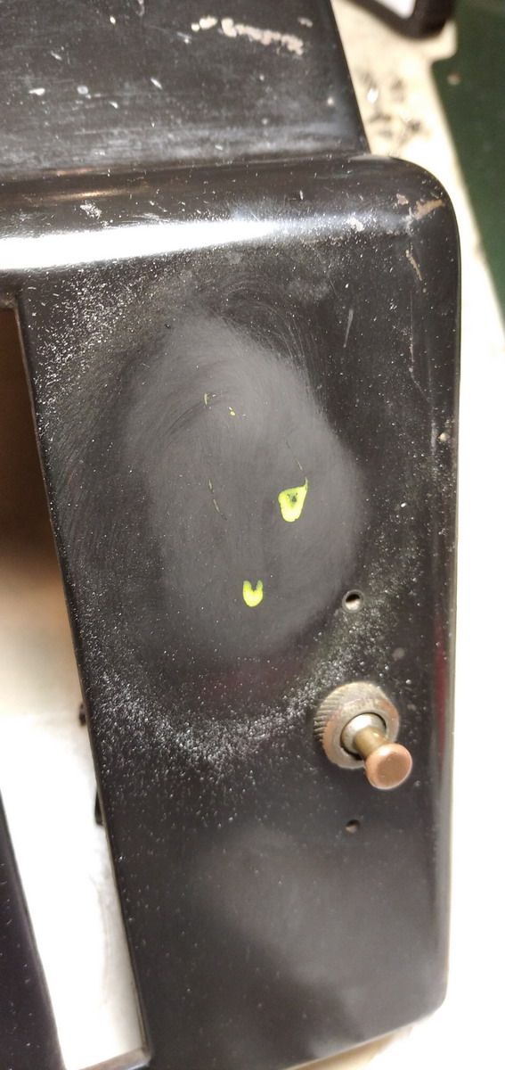
The machine had yellow paint spilled over it, which was carefully removed with persistent application of fine steel wool.
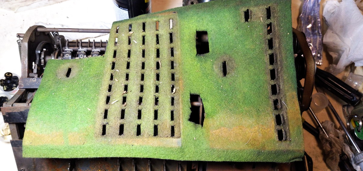
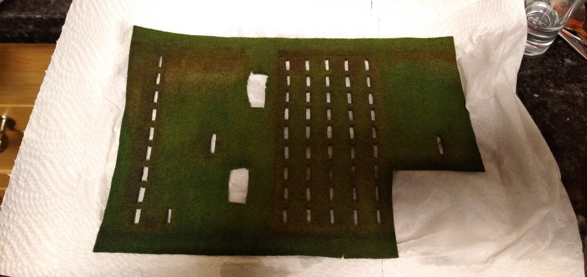
The green felt was removed to reveal the horrors that lay beneath...
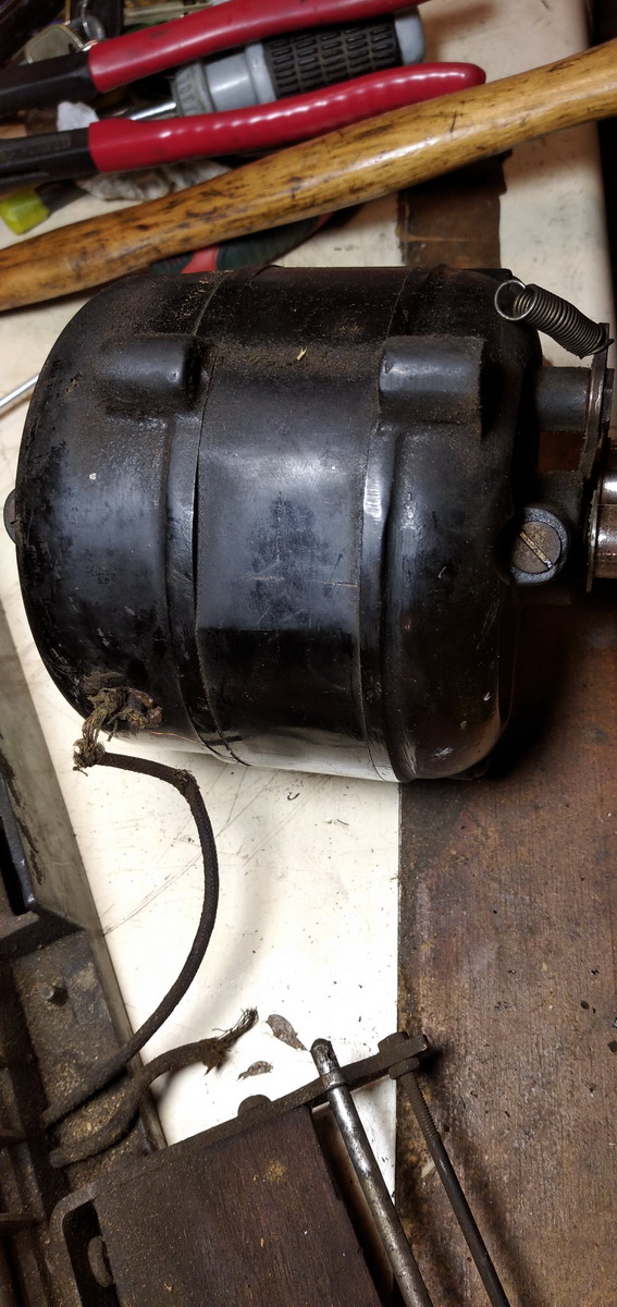
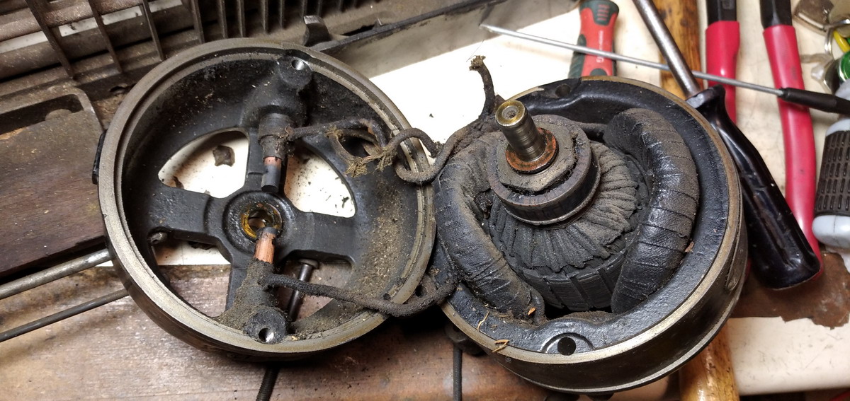
The motor was taken off, opened up and cleaned, awaiting testing. It is a shunt motor that tries to run at constant rpm regardless of load (within limits, of course ...)
The felt was taken off and cleaned thoroughly with vinegar in order to try and take out some of the rust stains.
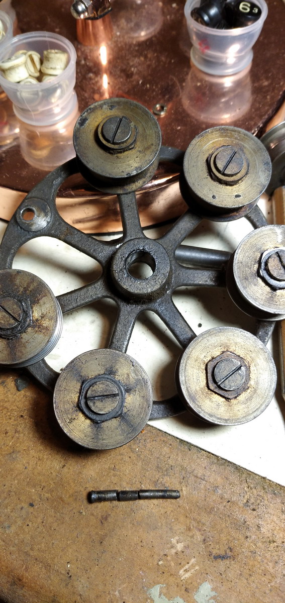
The large cast iron wheel was taken of the drive axle in order to free up the “satellite” wheels. You can also see the keys being cleaned.
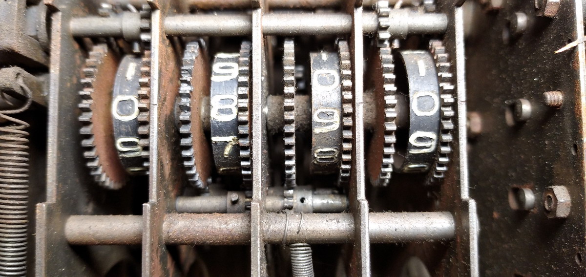
That brought us to the counter register, which did not seem to function. The reason for that was that two of the gears on the intermediate shafts had been disconnected or broken. This was rectified, and pins reinserted where they were missing. The axle that had been broken where it was drilled for a pin was glued to its gear with cyanoacrylate glue.
But that was only the beginning of the story for the counter register, because it turned out that the two untouched wheels which had been functioning all along, and to which I aligned the “broken” two wheels, would reset not to 0, but to 4 - so the entire counter register did now reset itself to 4.
So that meant that for every digit a lockpin had to be removed from a gear on the intermediate axle, and the wheel rotated in such a way that it would display zero. Here’s the first one, after some experimenting:
When the correct position had been found, the other three could be aligned with respect to that first correctly positioned counter wheel.
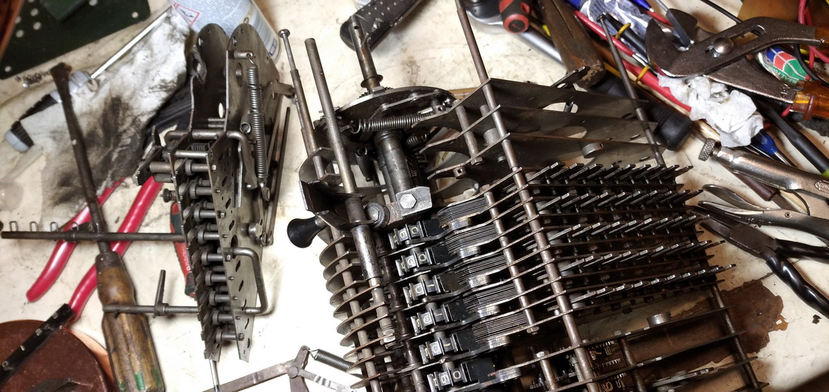
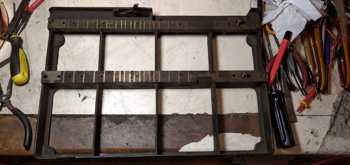
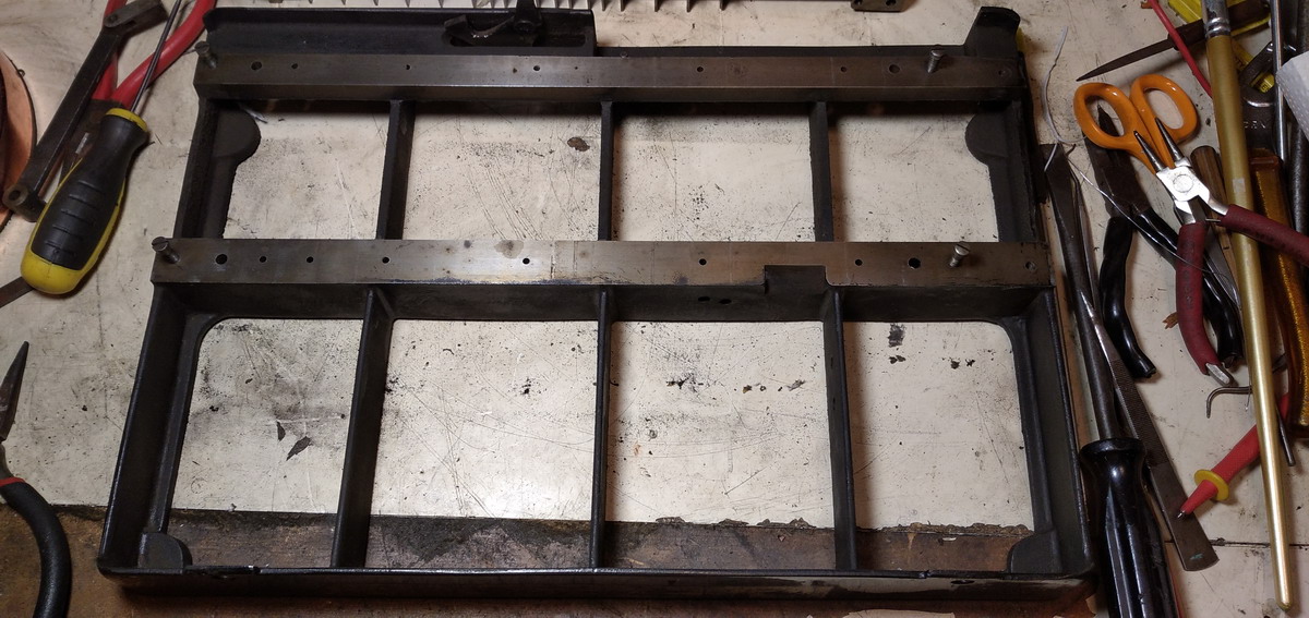
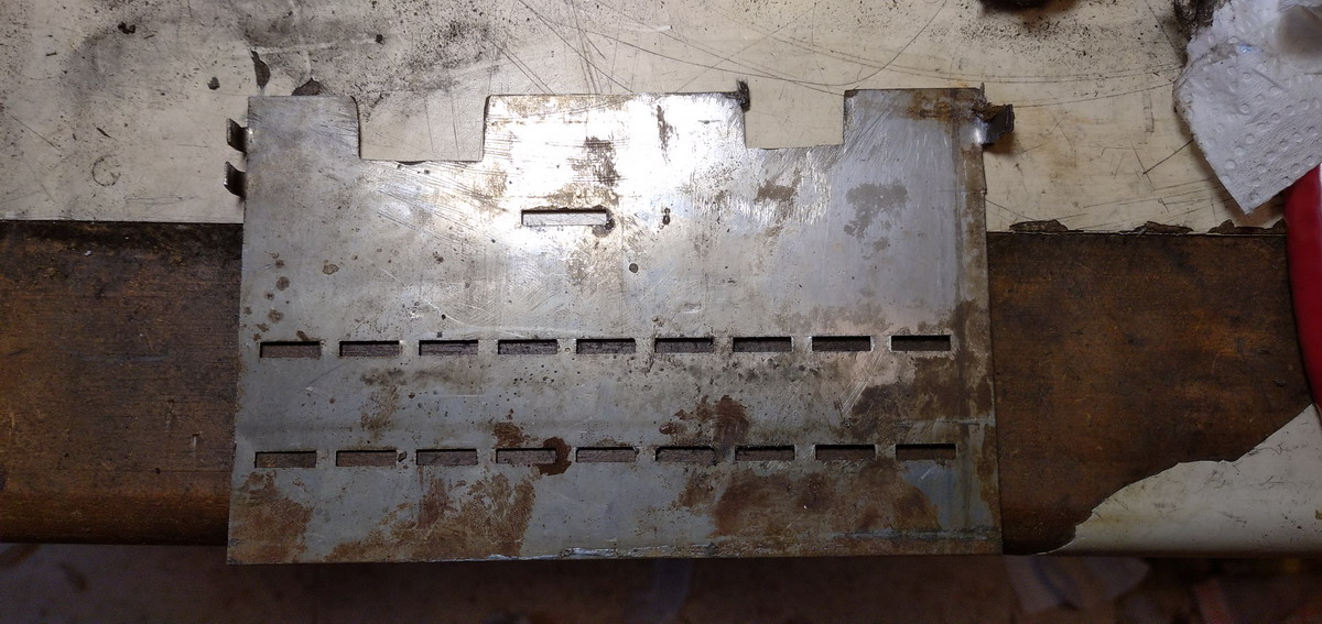
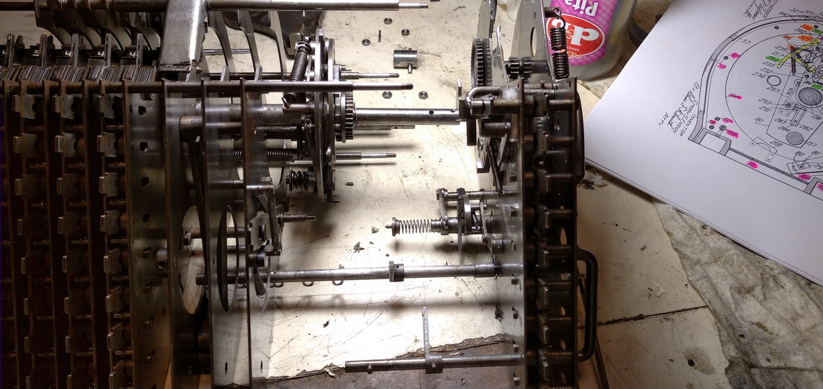
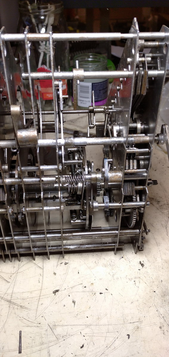
Now something needed to be done about cleaning. Taking the machine apart in its main build groups turned out to be impossible - once it is taken off the base plate, it becomes clear that it it held together exclusively by rods with bolts on their ends going through all the plates that make up the machine, separated by spacers. There is, however, a rub. The drum axle has roller bearings on both ends, but on the left end, there is a kind of eccentric/actuator, that appears to be an integral machined part of the axle, and does not fit through the bearing. The axle thus has to come out at this end ... but on the other side of the bearing, a rather substantial steel disk is pinned to the axle, and I couldn’t easily remove the taper pin.

In practice, that meant that the left end plate of the machine would have to come off entirely, but then still the lock mechanism on the right end of the rotor would not fit through the holes in the plates that make up the body of the machine. That would mean disassembling the machine section by section from the left, and the keyboard could not come off in one piece, because it would not fit between the rotor and the lock mechanism. So I started disassembling on the right, and took the multiplier section off, first the support for the bearing ...
and then of course documenting very well how the lever system was put together originally...
...as well as all the connection to the rest of the machine, while slowly extricating it
...phew!
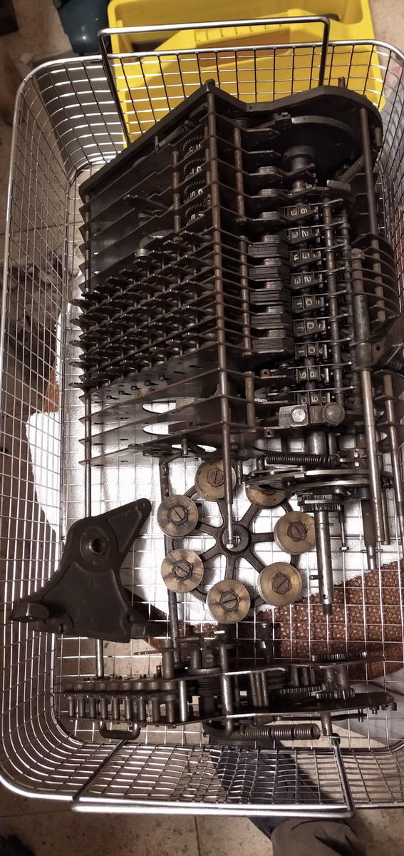
I decided against further disassembly, and just put the whole thing in the ultrasonic bath at this point.
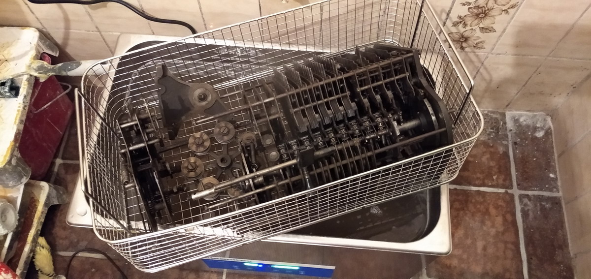
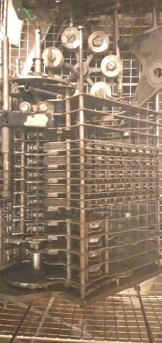
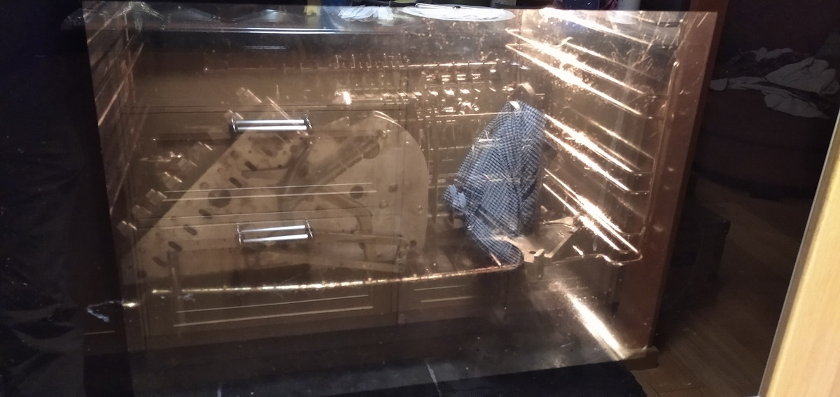
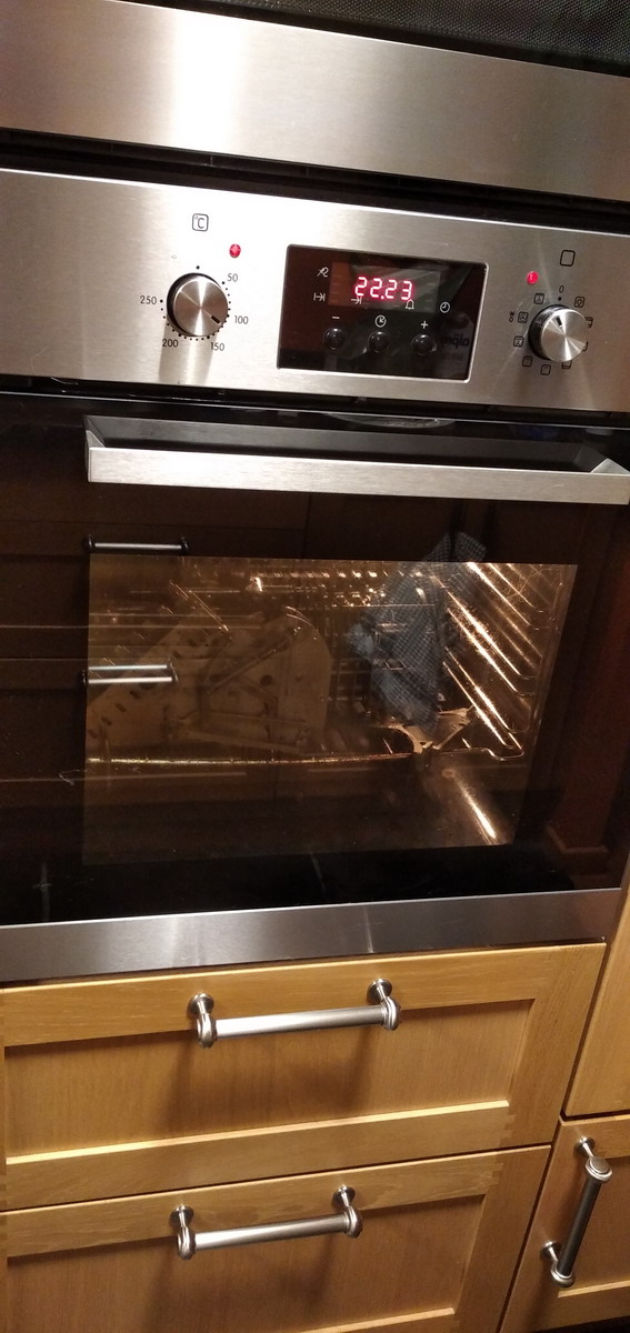
...and after a flush with deionized water, in the oven to dry out (not until crispy...)
That looks a lot cleaner already!
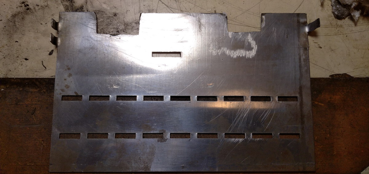
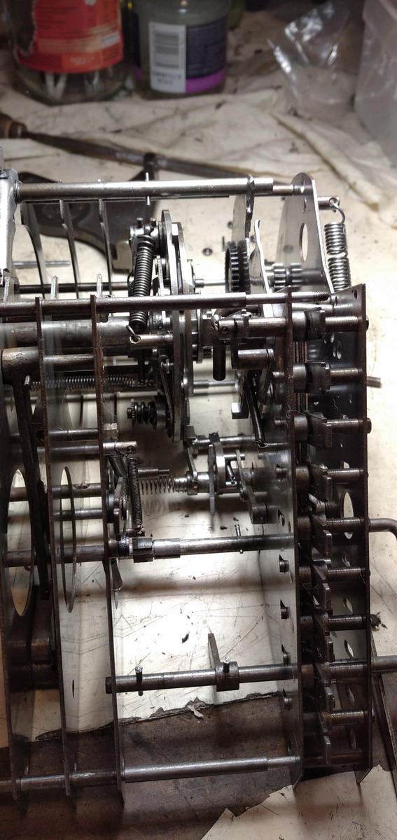
Now everything that had been frozen by rust and filth could be worked loose and oiled, starting with the keyboard - the thin steel plates that make up the actuators for every keyboard row still needed a lot of derusting
much better ...
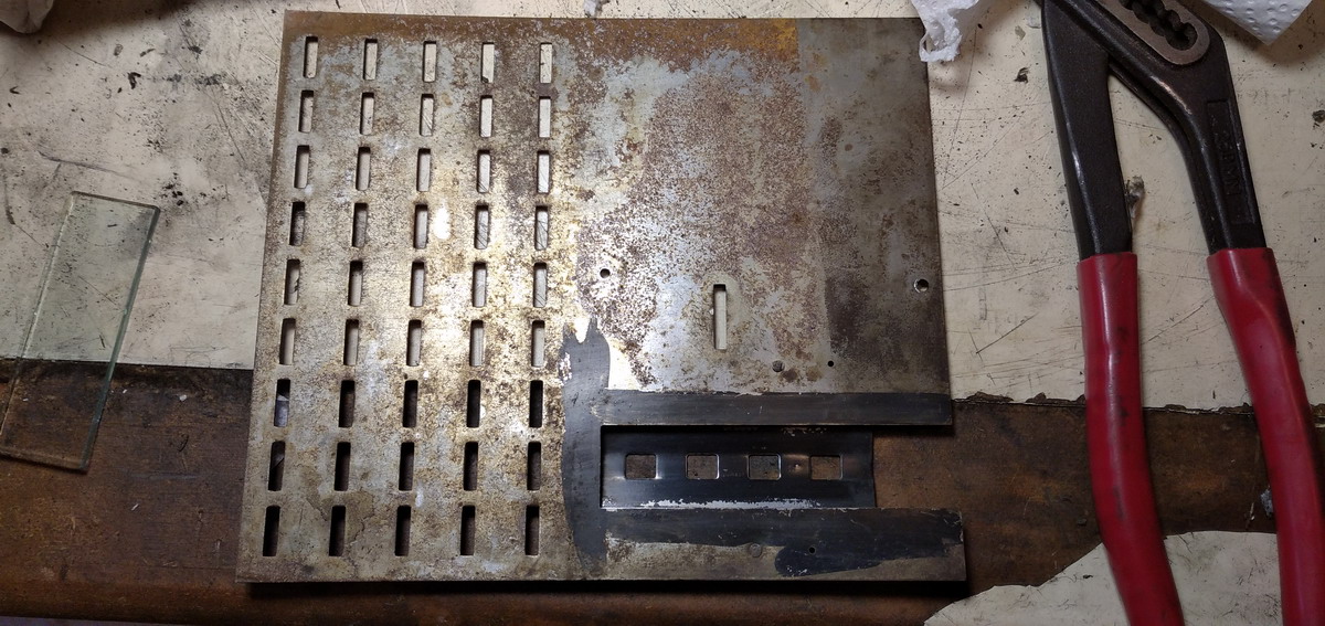
The base plate could also use a clean
As could the steel plates that make up the base for the keyboard and the front of the machine. A bit of fine steel wool made short work of the rust.
And then it was down to mating the multiplier with the main part of the machine again...
...slowly ...
...and done!
With everything back on the base plate, functionality could be tested by hand, after remounting the righthand bearing plate.
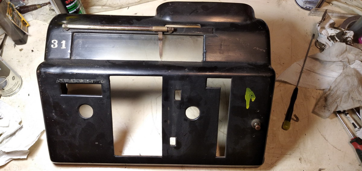
Then it was on to cleaning up the case, and finally the motor in order to be able to test the machine electrically and see whether the momentum of the drum was sufficient to wind up the springs all the way to the stop. The motor runs continuously until it is switched off by the switch at the front panel. It was in a very dirty condition, so needed cleaning ...
Also all the mounting hardware needed cleaning
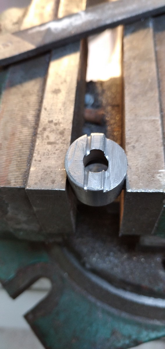
...and a new taper pin needed to be turned for the “satellite wheel”
After that, the motor was remounted
And this is the first test. It is surprisingly quiet!
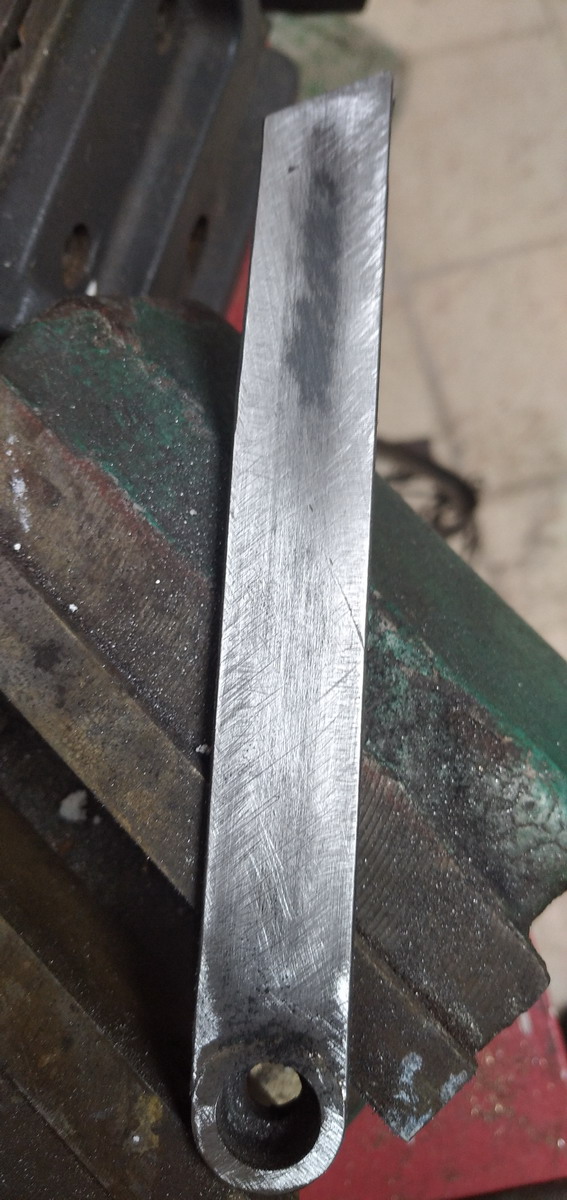
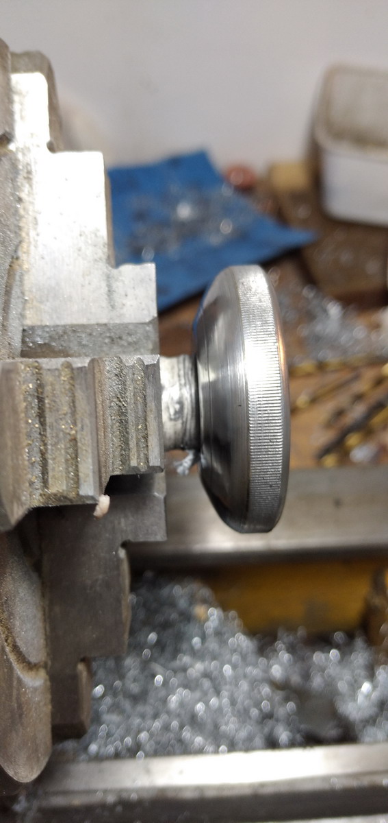
A start was made with the definitive handle. For this, a round sleeve was turned, drilled and filed to key into the position for the lever on the machine.
A straight handle in 3mm steel was silver-soldered on at the right angle.
It was cut off horizontally, and a horizontal piece soldered on to receive the square plastic handle. This would conceivably have been made of the same materials as the “Add” bar, but I’ve opted for black painted wood. This was attached via two countersunk holes in the steel handle, with wood screws.
All that was left to do then was a coat of black paint.
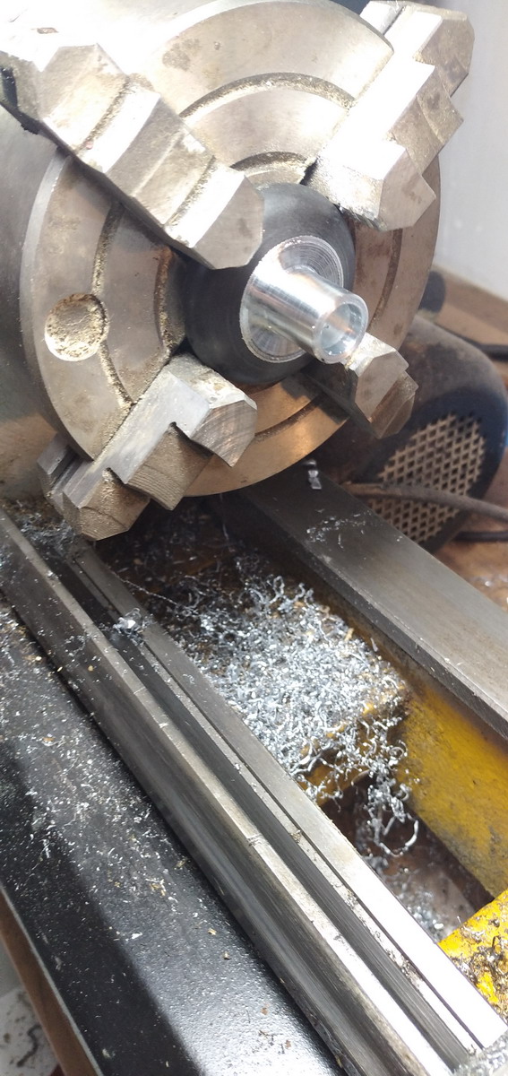
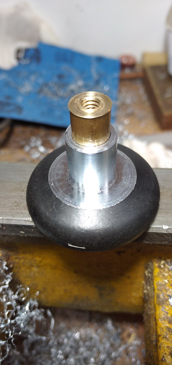
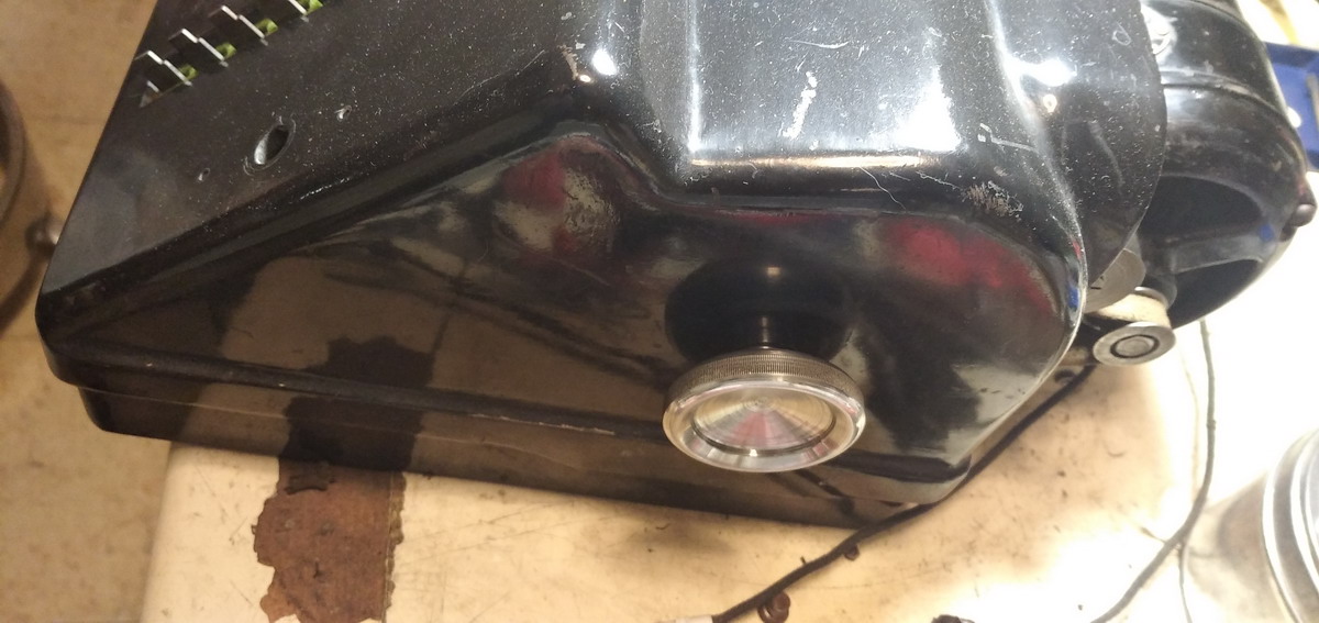
A hand knob was made for the machine - the screw thread it mounts to is left-hand 1/4in 20tpi, so a tap was ordered. The knob started out as a 50mm aluminium doorknob coated in black. The knob was a bit too short and interfered with the housing of the machine. The brass 12mm test piece for trying out the left hand tap was fitted into a 12mm hole drilled in the back of the knob with loctite, and quite a bit of aluminium turned away. To finish, the knob was knurled with a nice straight knurl, and in aluminium, this is really easy to do.
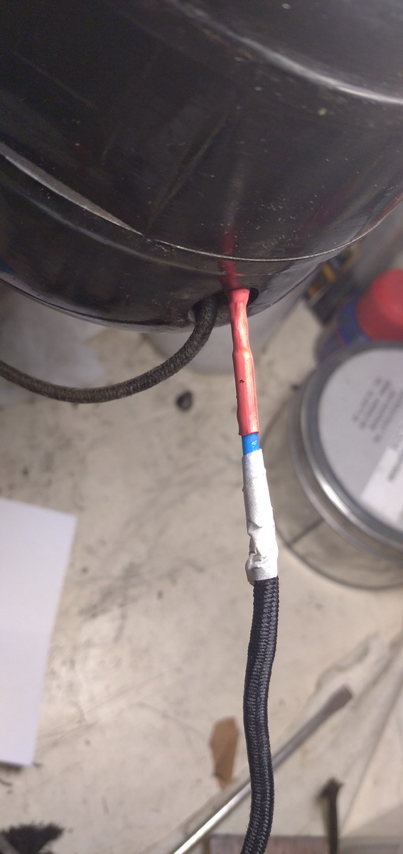
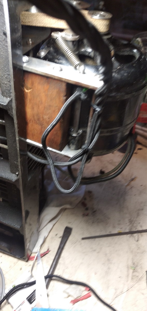
That only left the rewiring to do, and mounting back the housing, and then casting the two missing keys. Rewiring involved buying cloth-covered wire. I opted for a braided three-wire variant of 1mm², so I could add a ground to the machine for safety. This was hidden under the motor, connected to the motor mount.
The housing had to be mounted back onto the machine (although this would not be the last time it had to come off ...) It clips in place at the front with two pins, and then tilts back onto the machine. The upper Add bar support needs to be fed through its hole, and then a very strange and annoying clamping device needs to clip the back into place. That could have been designed a bit better to be honest. There are more pins present for the mounting of a motor cover, but that is missing in this machine.
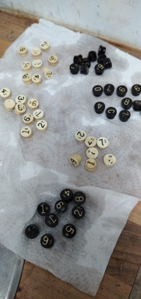
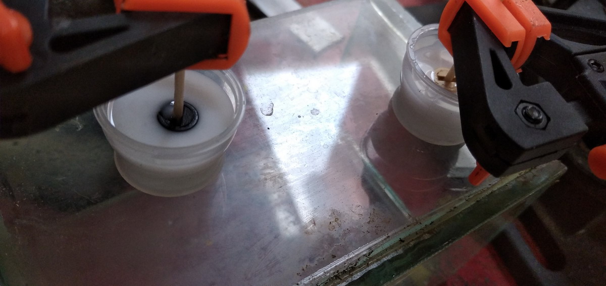
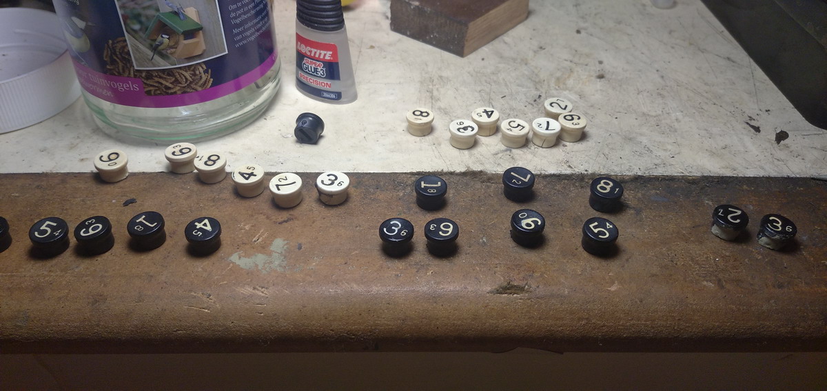
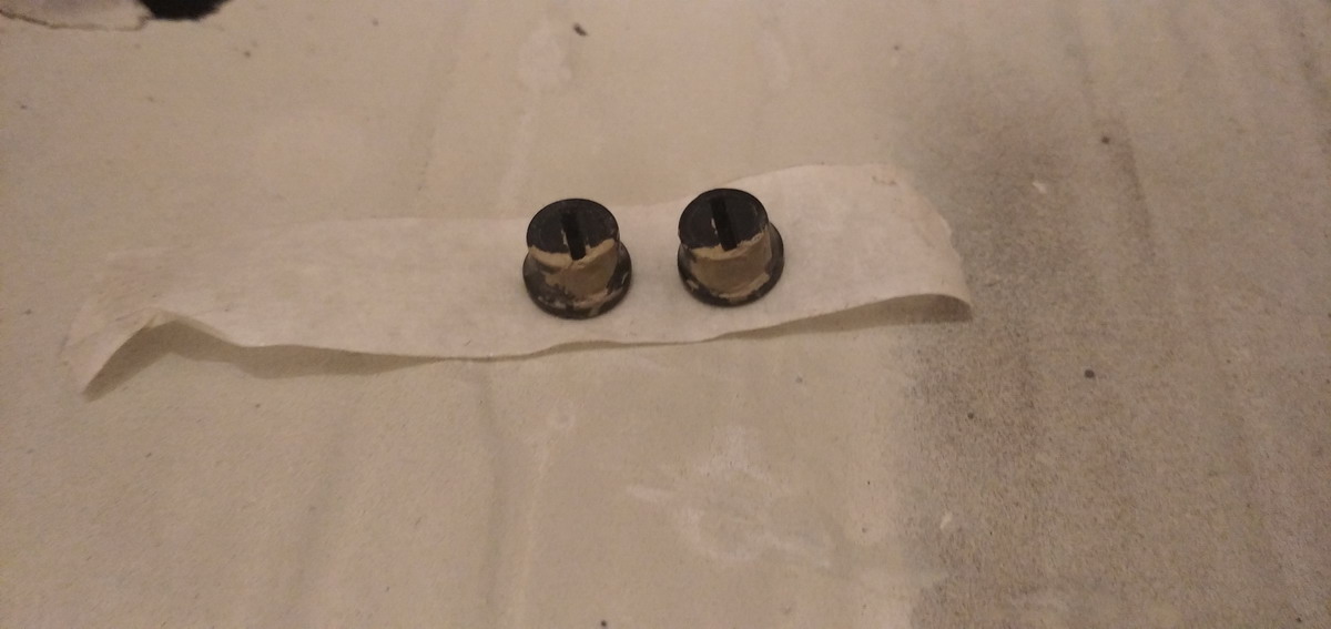
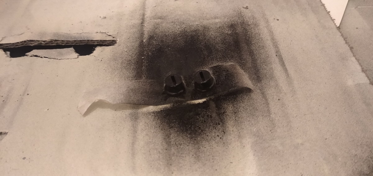
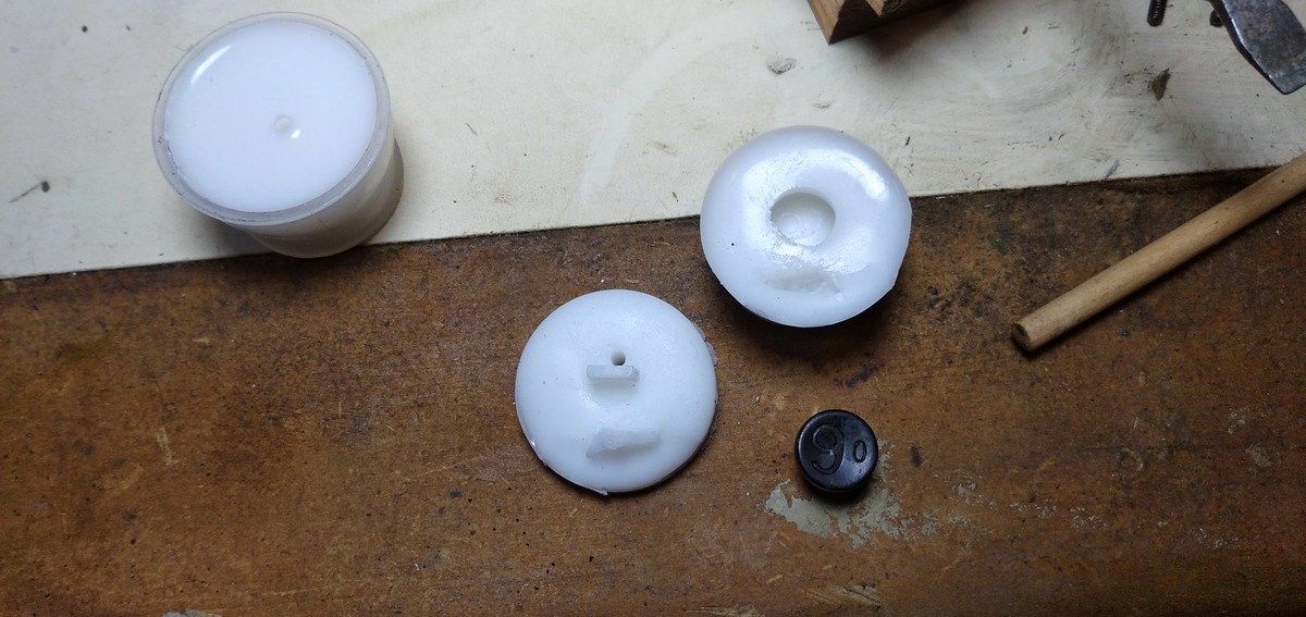
The final step was to cast the keys. This involves weighing and mixing the silicone...
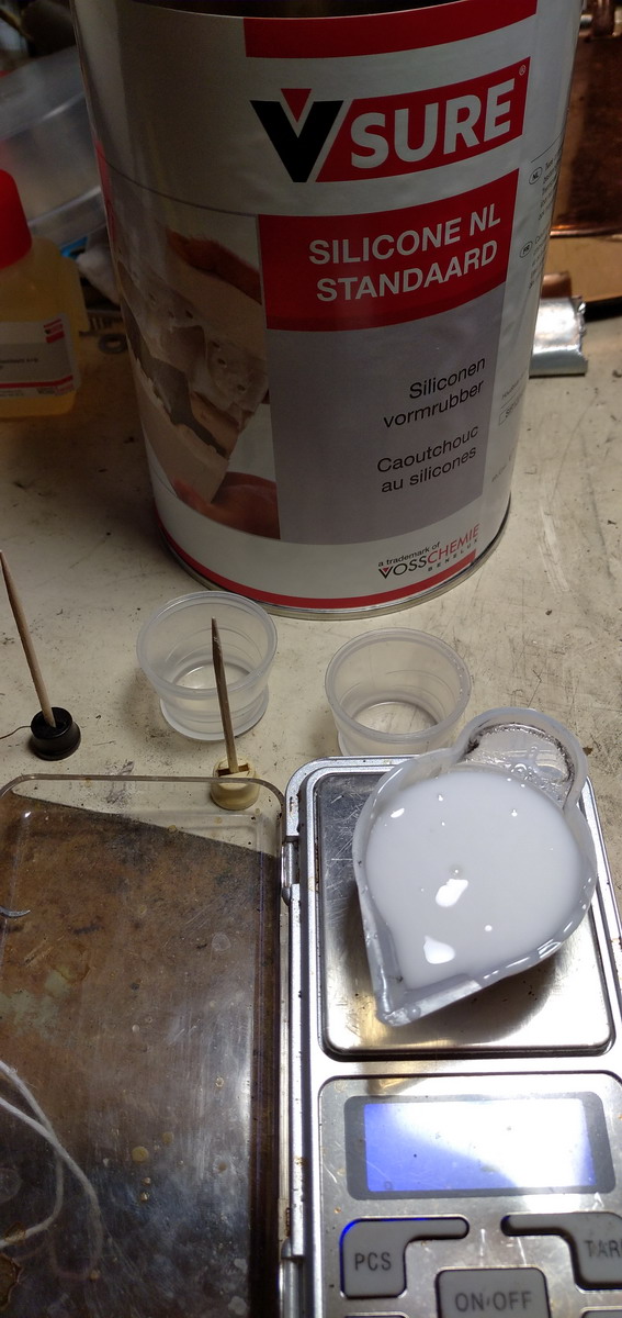
...covering the detail on the top of the keys with it...
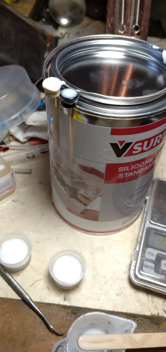
and then plunking them (technical term, that ...) upside down into a cup of silicone mixture that needs to harden for 24 hours.
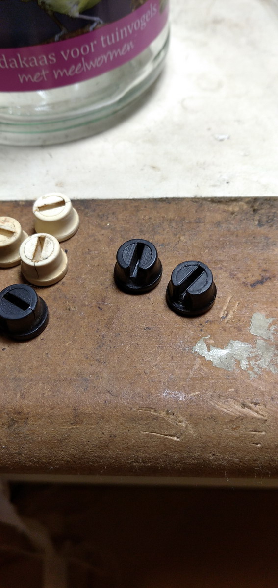
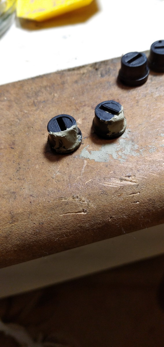
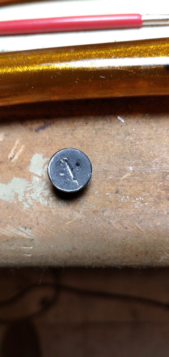
While the moulds were hardening, I repaired all the cracks in the other keys, and filled up the missing parts with car body filler.
With a next layer of silicone on top of the mould also hardened, it was now time to check whether it worked...
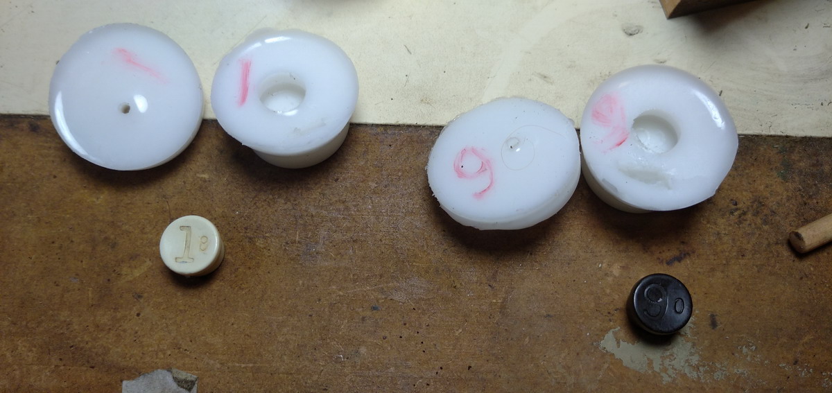
The keys used were filled again with the paste that is necessary for contrast ...
There is by the way, a long section in one of the patents in which Emory Ensign goes on at length about the coloring scheme for the keys - he likes to have the rightmost keys, representing cents and dimes, black, then three columns of white keys, then three black, and one more for the millions, white, but he adds that “it is obvious that the keys may be readily shifted about so that any arrangement can be had”. However, he also adds (and does not put that into practice with this machine ...) “It is very essential, however, not to have a deceptive key-board, that all of the rims should be of the same color, preferably white, so that all of the keys will appear exactly the same size, especially when a green back-ground is used.” Hmm!
Another interesting tidbit from the patent is that the machine could be provided with an “indicator”. As the adding plates are shifted forward by operation of the keys, you can see them stick out at the bottom of the window which displays the result. Emory imagined that numbers could be printed or engraved in mirrored script on the side of these plates, and then visualized through small mirrors under a 45° angle, so that there would be an input control register in this way. He adds in his patent “When desired the machines can be built without this indicator, in which case the operator would tell which adding plates were being depressed by examining the adding keyboard.” And so it happened ...
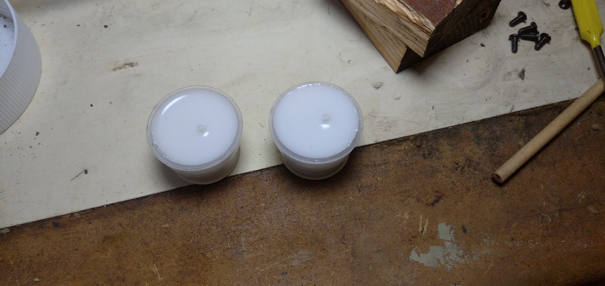
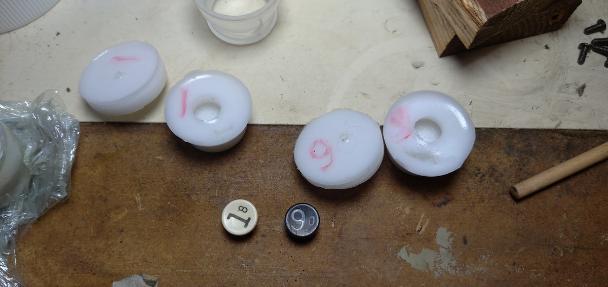
Now, while the moulds looked good, the proof of the pudding is in the eating ... so some keys were cast.
The first casts came out a bit grey, and there were air bubbles in the 8 ...so I tried again
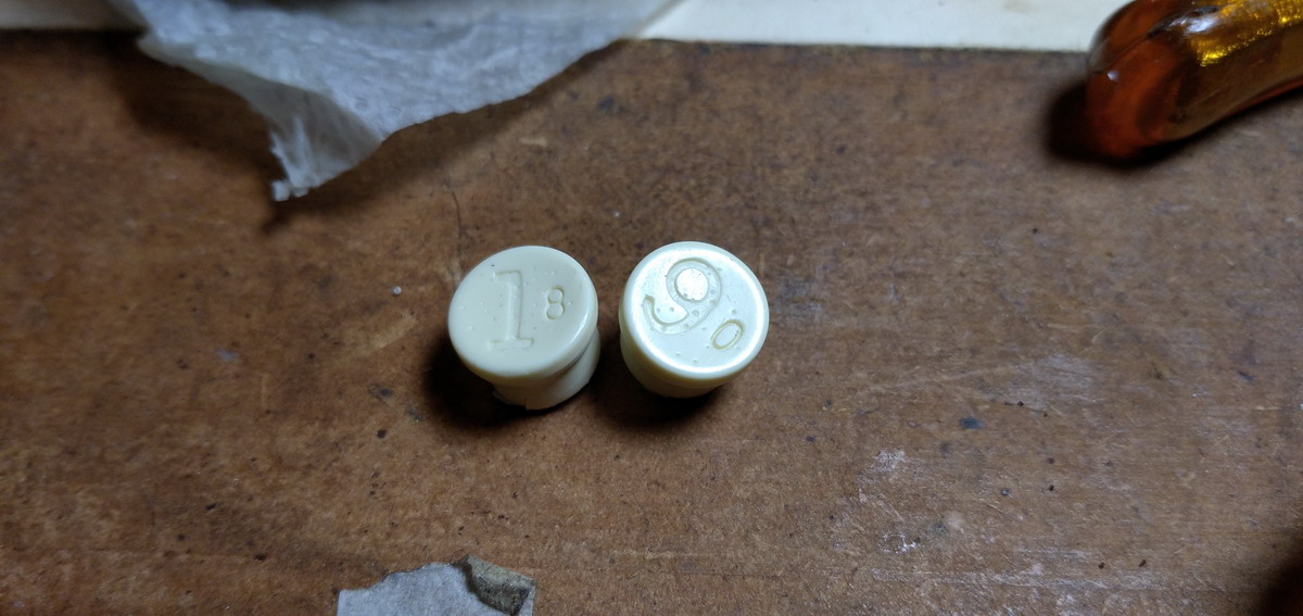
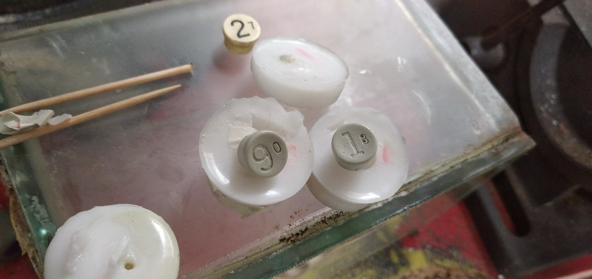
One of the grey keys was transformed into a division key:
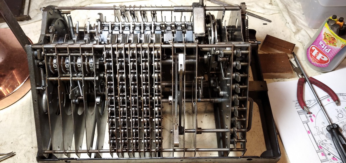
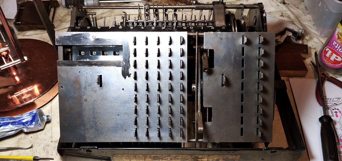
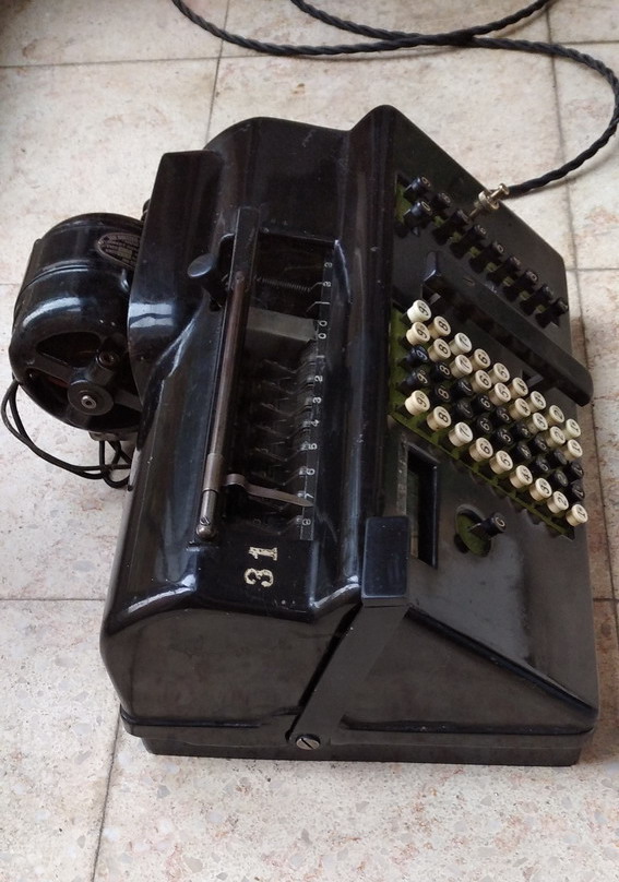
..and that finished the machine. So first some pictures. Remember, this is what it looked like when it got here:
And this is now:
And then finally a video of its operation. Some notes can be made about this. First off, the “C” key is not working properly in this video yet. When pressed in, it prevents (accidental ?) operation of the keyboard. If you want to keep the numbers you set in the keyboard, use the “multiply by 1” key instead of the add bar, because that will always clear out the keyboard. The “C” key should prevent the keyboard from being cleared when the clearing lever is pulled, but that did not yet work well - so there was at this stage no way of clearing the counter and result without resetting the keyboard. By keeping the carriage not in its leftmost position, the numbers in the result register can be kept while clearing keyboard and counter. Keeping the counter while clearing the result is possible by being careful not to pull the clearing lever too far, but just until the “meter” is released and starts to rotate.
Since the machine can only add, complementary numbers have been added to all keys. This takes a bit of getting used to, but it also had unexpected boons. Subtraction is the strangest operation to perform. if we have 999 and we want to subtract 333, then we have to look at the complementary numbers on the keys, and key in one *less* than the number we need to subtract. So we key in 00332, looking at the small numbers, essentially adding 99667 - the result is then 100666. Ignore the leading one for the result of the subtraction: 666
Division is even weirder. The example in the video divides 365 by 52 - or in other words, if a year were divided in exactly 52 weeks, how many days would each week need to have? We set up the machine with 365 in the result register, and looking at the small numbers on the keys, key in one less then the divisor - 51. But subtracting 52 from the leading two digits (36) would give a negative number, so we cannot do that, and have to shift the divisor, instead keying in “051” in the leading three columns. This amounts to adding 948. Now it is just a question of guessing how many times it is going to fit, erring on the side of caution, because with this machine, if you overshoot the number, correction is not possible - it only rotates in one direction. If we subtract 52 seven times, we end up with a number smaller than 52 (namely 001). If we shift the carriage once, we have 010, still too small, so we need to shift again, to get 100, in which 52 fits once - so we subtract once. We end up with 048, ignoring all the leading numbers, so we move the carriage once space, have 480, and 52 will fit 9 times - we press the 9, and find 012, ignoring leading numbers. Now the cool thing is that there is an inherent proof of a division done this way, because there should be one leading zero added for every revolution, and hence the number that leads the remainder in the result register should be the quotient - and identical to what is standing in the counter register, in this case, 7.019
If something went wrong somewhere in the division ad-nd an error was made, this would not be the case.
Anyway, I will leave you with the video of this fascinating machine.