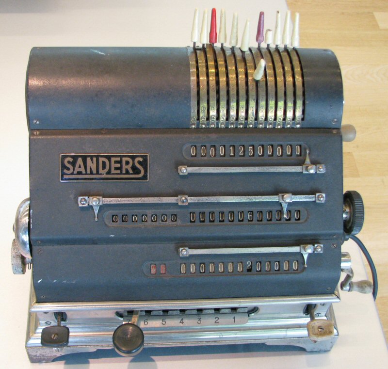
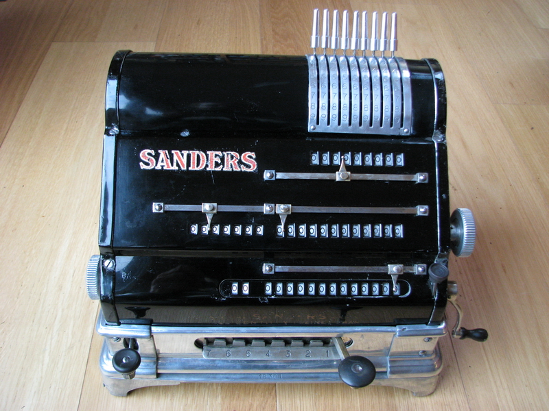
Sanders Calculating Machine
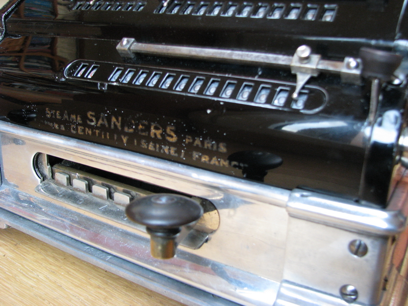
Despite its name, this machine is not American or English, but rather French. Nico Sanders, originally Dutch, hails from Paris, where "L'Eclair", as the machine was first called, and later "La Calculatrice Electrique Sanders", were produced and sold, as well as the "Ellis bookkeeping machine". The designer of the machine, according to Martin, is Count Roberto Taeggi-Piscicelli, a civil engineer from Naples, and the machine was manufactured by the Société Industrielle des Téléphones in Paris. Taeggi-Piscicelli owns the Patents GB191210148, AT62199, US1416974 and FR430730, the last of which has an application date of April 1911, and in which the machine is really already quite recognisable. The only thing that is not there yet is the subtraction button - the patent sheepishly mentions that if you multiply once too many times in a certain decade, that you have to clear the result register by hand and start over!There are two different incarnations of the machine, both shown on rechenmaschinen-illustrated, and they differ in numerous aspects. In the early machine (L'Eclair), the base is wood, the totalizer is also cleared by a knob instead of a crank, the totalizing knob is down in the base instead of right at the front of the totalizing register, which indicates that one or a few of the interlocks associated with it are also missing, there is a large lever on the right hand side which presumably clears the input, and the bell is on the left side of the machine instead of under the bottom. Another slight tidbit which escaped my attention until now is that L'Eclair has twelve input positions, whereas the Sanders machine has only 9. But the subtraction lever is there!
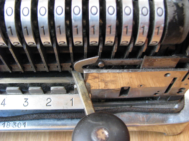
Very few examples of L'Eclair are known to be in existence. According to the patent application, Taeggi-Piscicelli was at this point actually living in Paris, in a very fancy apartment building. A 1924 newspaper article in French (to be found on the Sanders page in the rechnerlexicon) explains that the machine has been introduced in 1913 under the name "L'Eclair", and that now all the patents have been bought by Nico Sanders, a specialist in calculators, who has redesigned and improved the machine and is now selling it under the Sanders name. Indeed, Nico Sanders took out another German patent in 1922, which now includes drawings that correspond to the actual manufactured machine, and specifically mentions the subtraction/division button of the apparatus. The patent drawings are very good in clarifying how the machine works (including a detailed description of the switches and electric scheme) so you are encouraged to go have a look on espacenet. There were two versions sold, one with 9 input pins, and one with 12. The machine in the Arithmeum in Bonn is much earlier (although we currently don't know the serial number), and this machine does indeed have the 12 input positions and the input clearing lever shown in the advertisements below - as well as the external bell, a different design of the base, and the numeral wheels which are not fashioned out of aluminium. The looks of the top plate of machine nr. 18350 on rechenmaschinen-illustrated (the one presented is 18301) seem to indicate that three extra input slots have been covered by a plate to mask them. At this point they may have been using up parts the best they could.
It would be logical that Taeggi-Piscicelli stopped manufacturing calculators in Paris and returned to Italy when it got involved in The Great War in 1915. We do know that he was still alive after the war, because he published a book on the banking sector in 1922. He was a prolific inventor, with 34 patents to his name, many also about cash registers, an electric postal delivery van, then a completely electric postal system, railway ticket printing and dispatch machines ... finally he appears to have ended up in the construction sector, back in Rome, patenting in 1922 an improvement in the construction of concrete slab buildings.
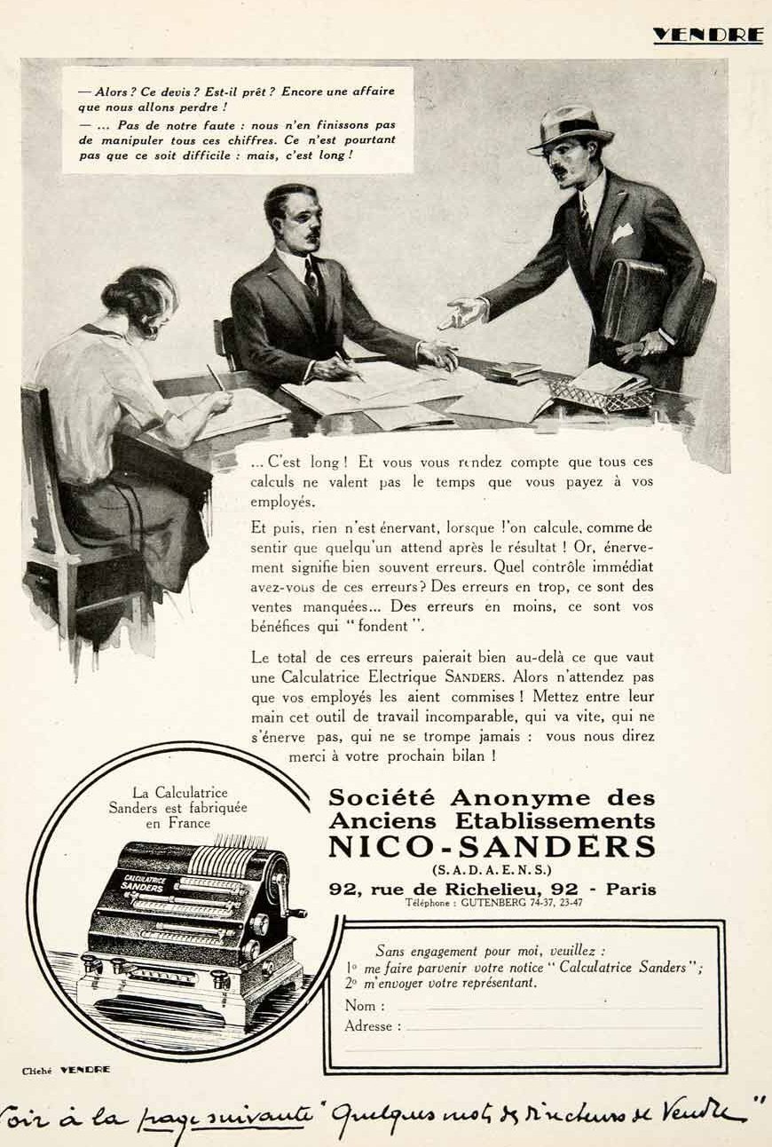
Nico Sanders himself is a bit of a mystery. He submits his patent application in 1922. After the sales of the Sanders Calculating Machine were taken up by the SA Nico Sanders, and the production by the Usines Gentilly (Seine), the company then very quickly (still in 1924) changes its name to "S.A. des Anciens Etablissements Nico Sanders" (S.A.D.A.E.N.S.), which sort of implies that he sold his part of the company (it means "The company formerly known as SA Nico Sanders" - a little like T.A.F.K.A.P. and Prince ...). Very little else can be found on Sanders himself (except that he is Dutch, and is still living in Paris in 1928, at the same address for correspondence as the S.A.D.A.E.N.S., Rue de Richelieu 92, Paris II - the building is still there.) Both he and the company keep taking out patents for bookkeeping machines, and in 1933 suddenly there is a patent by S.A. Nico Sanders again ... with an address in Gentilly. The building looks quite art déco (although badly restored), and it could really have been the "Usines Gentilly" mentioned on the front of the Sanders Calculators. This address is 50, Rue Benoît Malon, Gentilly.
If anyone knows more about what became of Nico Sanders, I would be delighted to hear about it.
The machine was, according to Martin, priced first at 1250 FFr, later at 1500 FFr. (Pre-war prices). Compare to a regular French pinwheel calculator, such as the Chateau, which was priced at 475 FFr. and later at 425 FFr. Three times the price, but of course a unique set of features ...
Now finally, about the machine itself. It is a very ingenious piece of technology. There are a number of unfamiliar levers and the operation is not quite straightforward when you are used to regular Odhner machines.
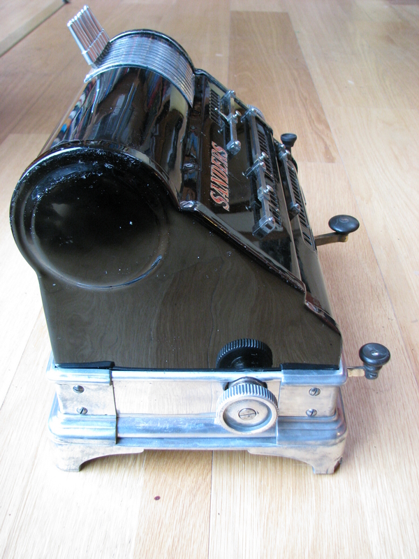
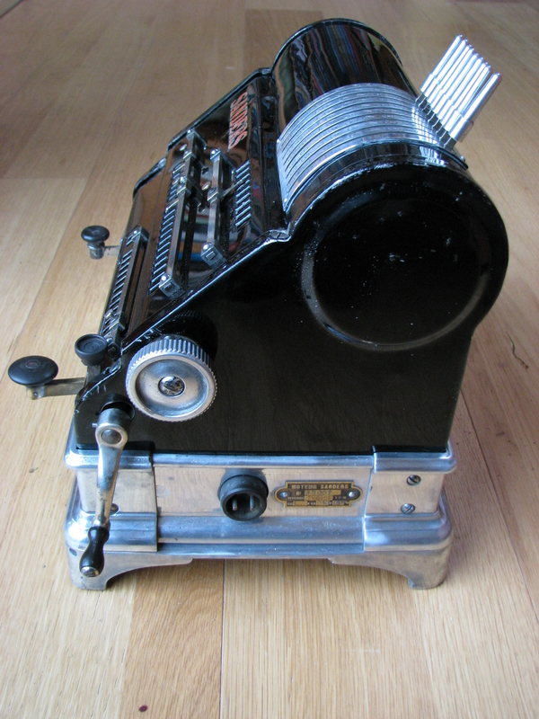
First of all, the machine is electric, so there is no operating handle. Electric power comes in on the right hand side, and is led by wires through the base along the front of the machine to the right side and then up to the motor at the top. The knob connected to the "crank" of the machine is on the lower left side. Other electric Odhner type machines have the motor sitting on either side along the main axle, where you then usually have a dummy crank stub, but this machine is different. It uses setting sectors, which are only brought into contact with the pinwheel cylinder when the machine is in the "setting/rest" position - more about this later. This also means that the input pins remain stationary, quite a novel idea, as the other manufacturer who thought this up in 1911 (Brunsviga) used a completely different implementation, and to be honest, their system is inferior to this one.
So, stationary setting levers and no crank - what else is special about this machine? It has a result register, and a totalizer, which sums up the totals in the result register when clearing it electrically. One quickly learns that, although there is a manual clearing knob on the right hand side of the machine, just totalizing to clear the result register is much faster. The totalizer itself can be reset with the large crank on the right hand side, and only manually.
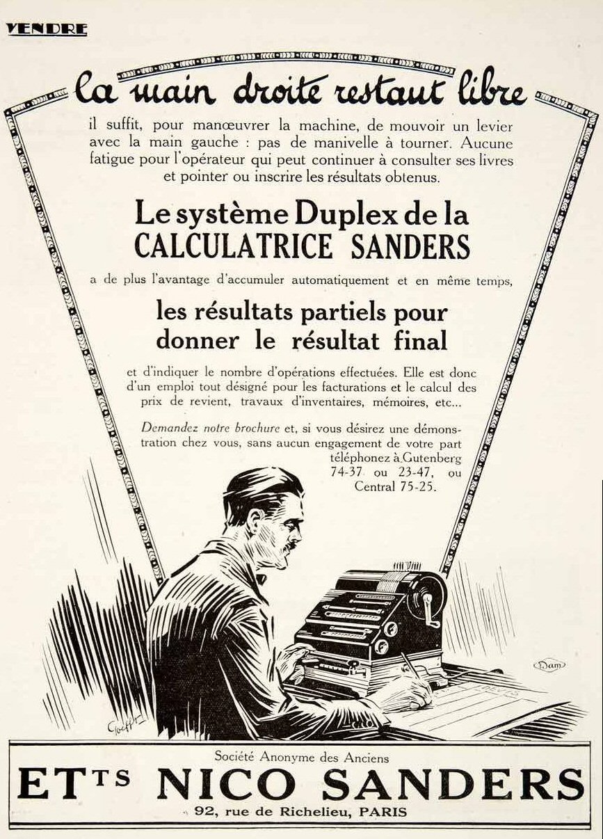
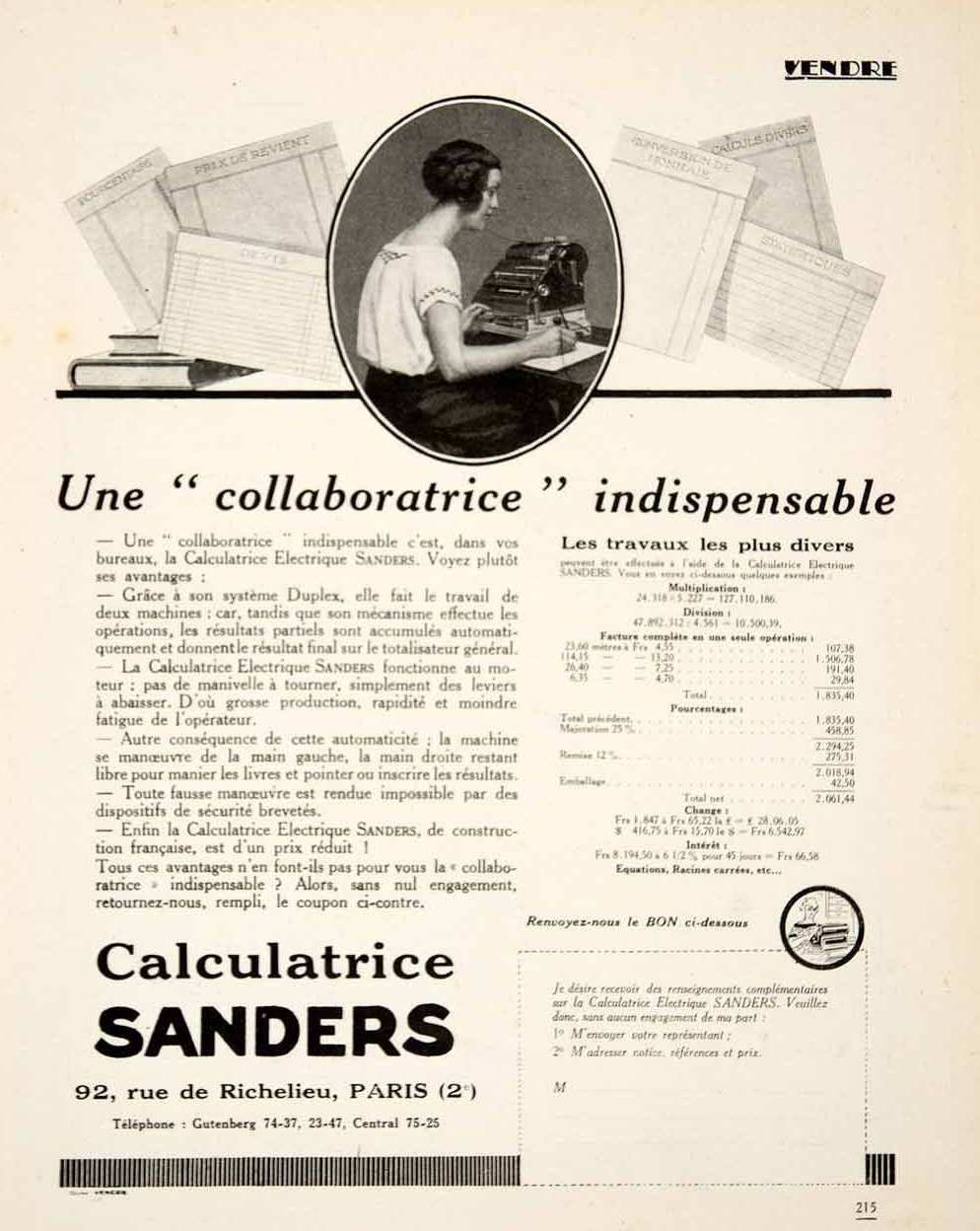
A unique feature of the machine, as stated also in the publicity for it, is that it can be operated completely with the left hand only, with the machine on the left hand side of the desk, leaving the right side and the right hand free for noting down the results. That is also a feature which is truly unique. Advertisements below are from 1924, 1924 and 1926. Do note that the input clearing lever is present in all of the advertisements, whereas only the early machines actually have it. It rotates a quarter turn to the front to clear the input.
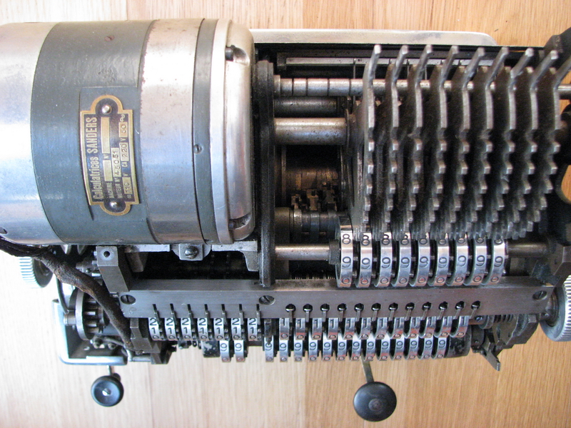
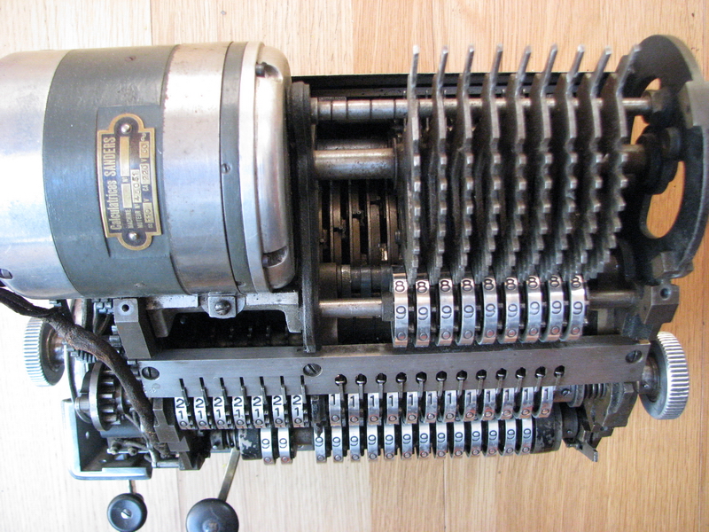
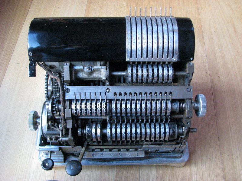
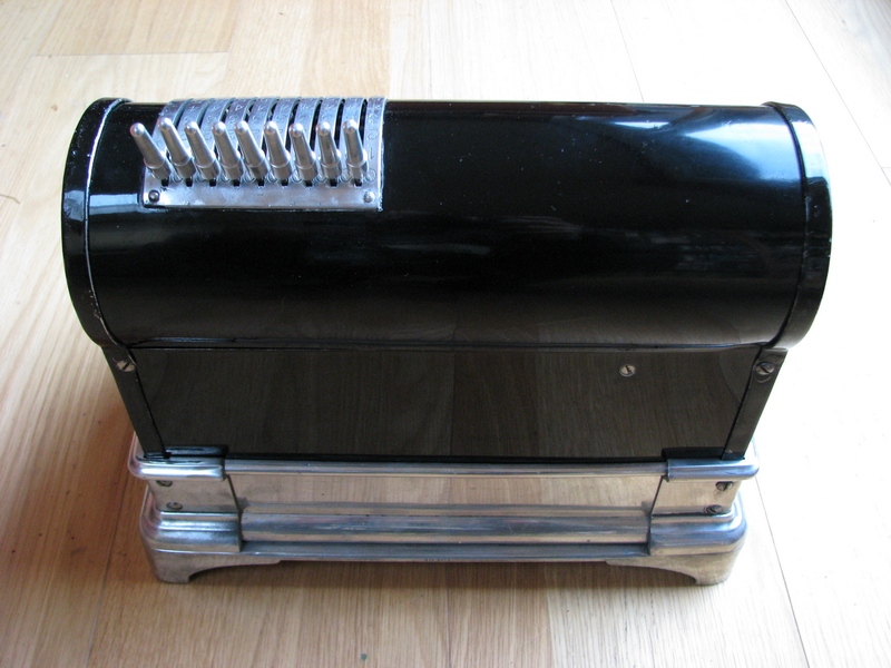
First some "undressed" pictures of the machine.
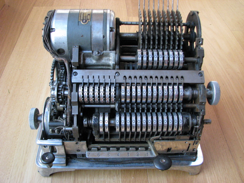
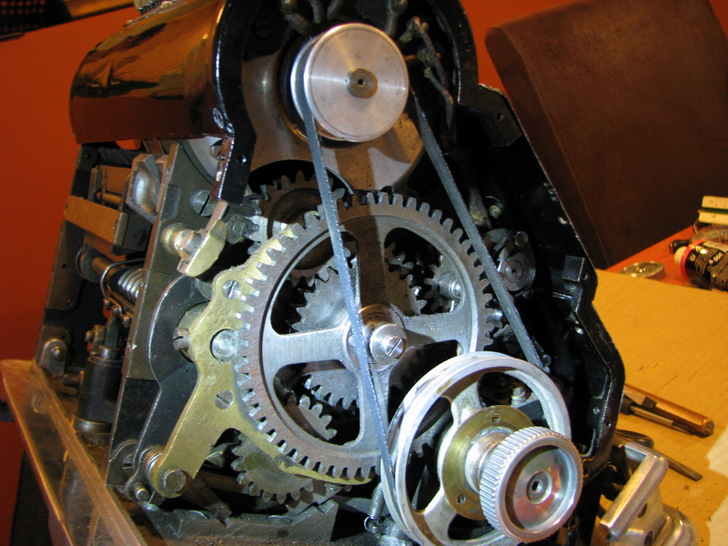
So what do all the levers and knobs do ? It is easier to understand what happens when going through the machine from the motor to the totalizer. The motor is at the complete top left end of the machine, next to the setting sectors, where there is a convenient place in the housing of the machine to put it.
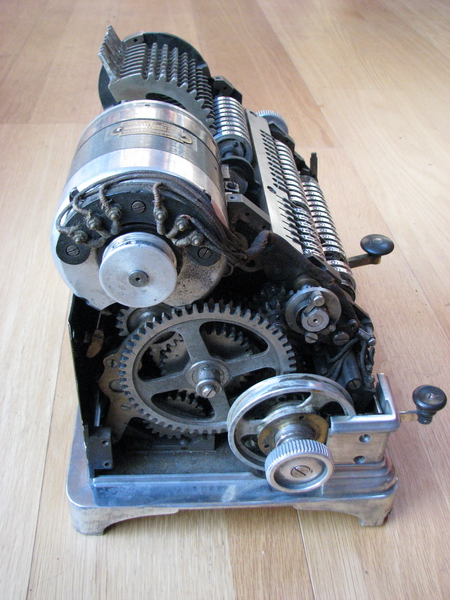
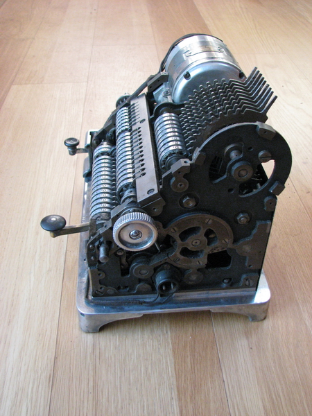
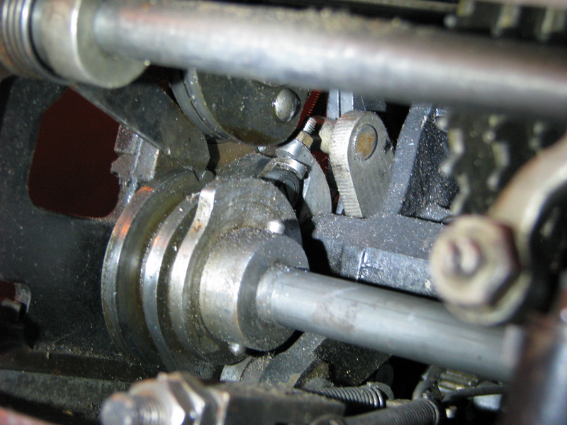
It drives the mechanism through a leather belt (missing in these pictures), which slackens with time, so the machine will start slipping and need manual assistance to get through a calculation or the clearing of a register. The main wheel of the machine turns counterclockwise in normal operation, and drives the rest of the mechanism through a gear train. It is to this large wheel and the start of the gear train that the manual operating wheel is connected, so everything that the machine does electrically can also be done manually by turning this wheel.
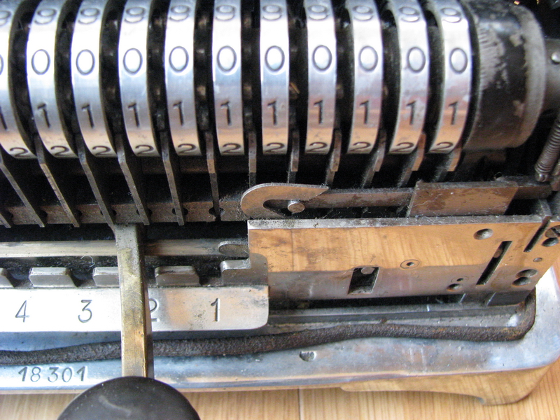
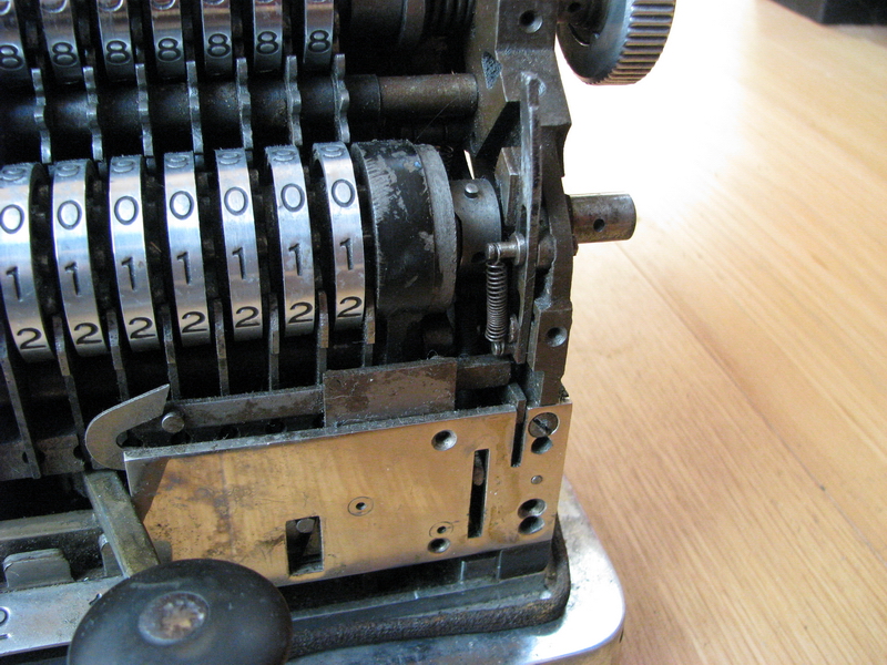
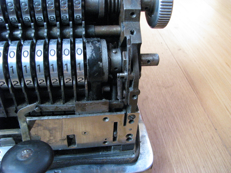
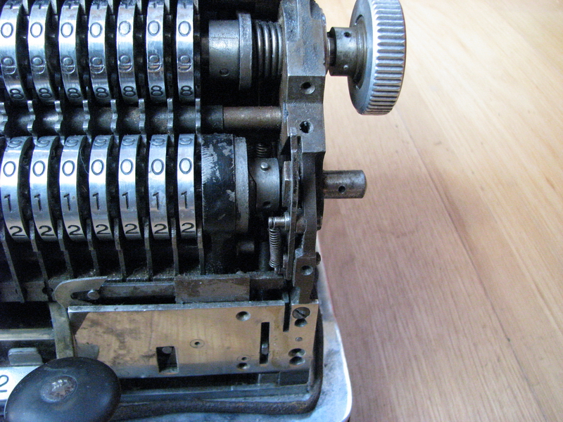
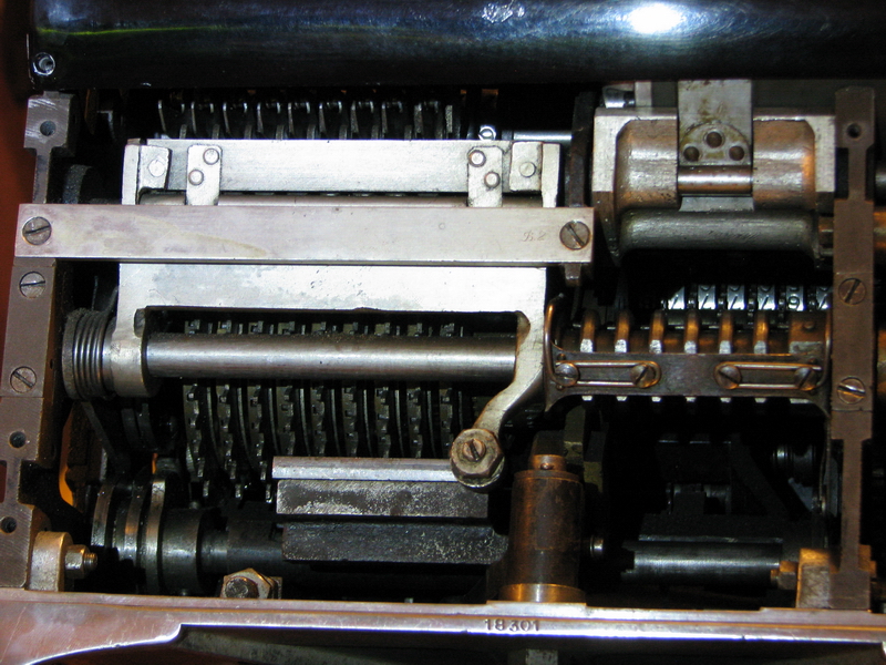
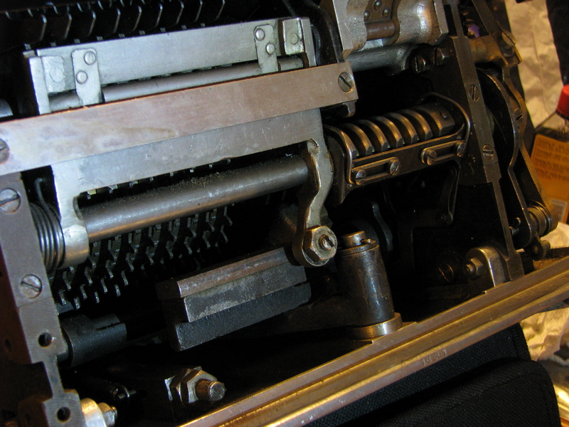
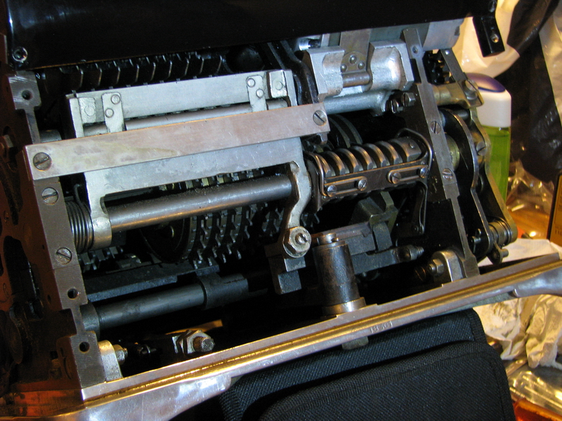
The motor is switched on in the normal direction by pressing the large lever on the front of the machine down. The function of this lever is threefold - it selects the decade to which to add the input by moving through the columns 7-1 from left to right (what it does is to move the entire pinwheel cylinder from left to right on its axle), starts the motor by depressing the lever when none of the interlocks are active, and it serves in its rightmost position to bring the pinwheel cylinder into the setting position, where the setting sectors can operate on it. There is also an interlock preventing the setting pins from moving when the lever and cylinder are not in this position. Another interlock, discussed later, is very well visible in the 2 pictures below.
The smaller lever on the left hand side serves to reverse the motor direction, so when this switch is pushed in at the start of an operation, the main wheel turns in a clockwise direction, and the machine subtracts and divides. It also has non-automatic stop division, which is quite neat. We'll discuss the way to do this later.
Finally, there are two more knobs - one on the right hand side of the machine, which can be used to manually clear both the counter and rotation registers (they can only be cleared together), and the small black knob on the front of the machine (missing here, but you can see the steel stub on the right of the totalizer register) which is used to electrically clear the result and counter registers, add the result to the totalizer, and increase the two-digit item counter with one. Some pictures of this process below.
Main lever in rest position, interlock is now non-operational.
Button pushed, this also starts the motor. Note how pushing the button pushes against the interlock bar, which in turn pushes against a lever in the bottom of the machine - this is what starts the motor.
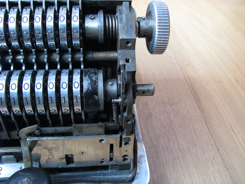
Start of the rotation, compare with next picture
The entire totalizing register tilts backward to engage with the result register, of which the contents are then transferred through a bank of gears:
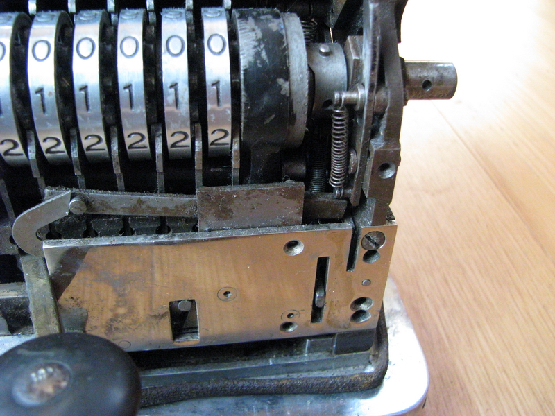
Still clearing - button has sprung back:
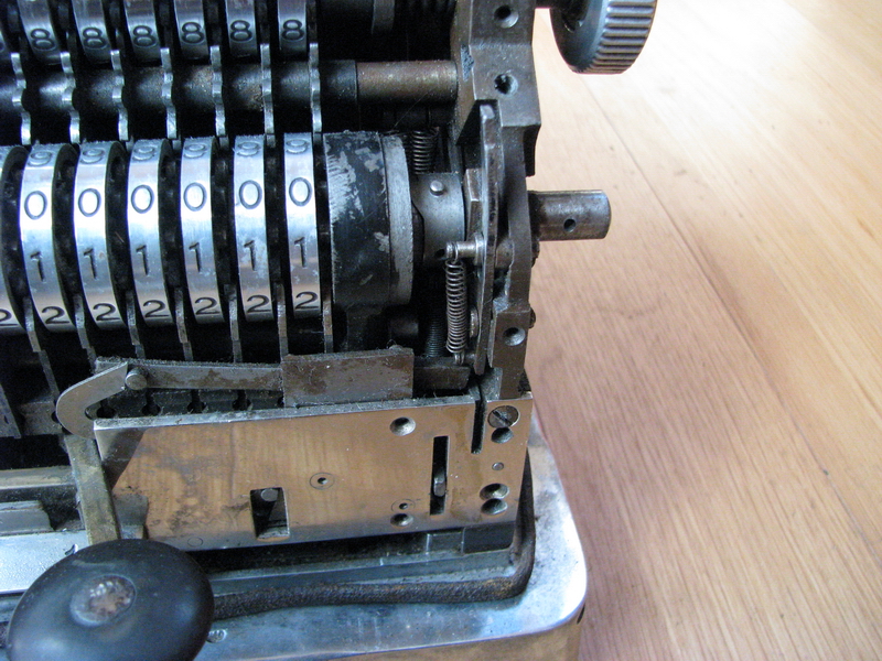
And tilting the register back - done. The rectangular steel part which holds the lever for the totalizing interlock has now also shifted completely towards the left. If the button for totalizing will now be pushed, there is nothing to push against. This essential part of the parts train in operating the totalizing function will shift back to the right and into its operational position after the machine has done at least one normal calculation cycle.
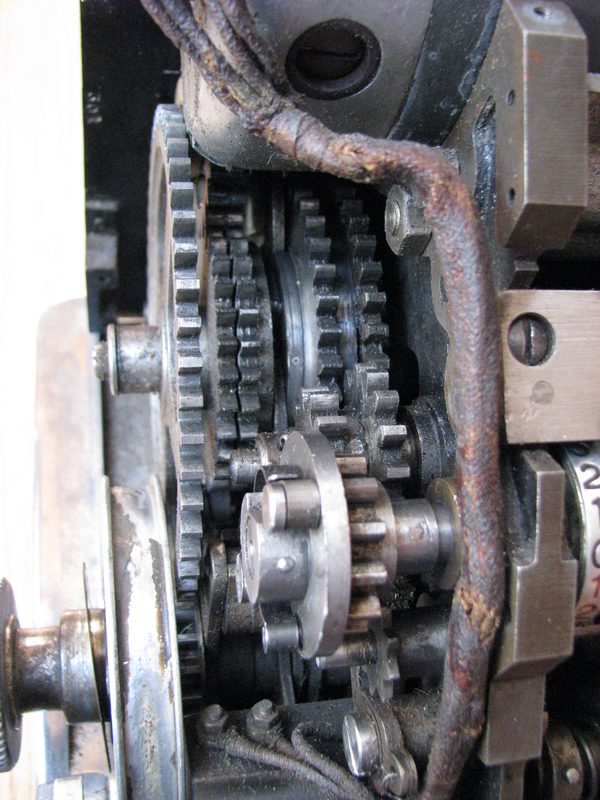
The machine has plenty of interlocks, mainly connected to the position of the main operating lever on the front. Essentially, when it is away from its resting position at the right end of the scale, you cannot do anything else with the machine than to operate it or clear the registers manually - no setting, and no clearing and totalizing are possible. The machine also resists all operation when the manual clearing knob for the result and counter register is not perfectly in the resting position, because damage to the registers might then result. For using the electric register clearing and totalizing feature, the main operating lever needs to be in its resting position, and the clearing and totalizing can then not be done more than once - there is an interlock that prevents a second totalizing operation before the machine has been operated normally for a regular calculating function, as already explained above. You can see the large number of cams and locks on the right side of the machine in the following picture:
All in all, a fascinating piece of early technology which presents a number of inventive technical solutions. I will overlook the part about it being electric - I usually only collect manual machines (I only have three other electric ones, only one of which is in working order - the other two I've been so scared of that I've never plugged them in), but I will gladly make (another) exception for this little (well, 23 kg) jewel. It is a machine which combines flair and inventivity with absolute sheer quality. The machine is incredibly overbuilt, uses plenty of overdimensioned castings, gigantic gear teeth, an overdimensioned motor and enough screws to keep it firmly together during a rocket launch to space. Even the numeral wheels are of all-metal construction instead of the usual plastic or resin in other brands.
The machine did have a number of issues when it came to me. First of all, the slipping leather belt. Operation would be OK if only a few numbers would be entered, but if there were too many, or a few nines, the drag would be too high and the leather belt would slip, needing manual assistance on the main operating wheel. Clearing and totalizing was even worse. I tried to shorten the existing leather belt, but it ended up breaking at the joint. This was relatively easily fixed by buying a new 510mm industrial flat drive belt in a kind of reinforced rubber compound. Here is a picture of the left side of the machine with the new belt:
Once the belt was replaced, it became clear that the motor needed oil, the commutator needed cleaning, as well as all the contacts in the switches. There has been far less smoke emerging from the machine since I did that, and it works very well now.
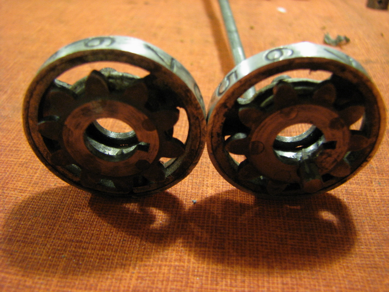
The second issue was a lot worse - one of the numeral wheels in the result register would not clear. This usually signifies a broken-off clearing tooth. I spent the better part of an evening to figure out how to get the register apart - since you cannot see what it looks like inside, it is somewhat akin to solving a chinese puzzle. This is where a service manual would really have helped. In the average Odhner machine, the clearing teeth have a slot to pass through in each numeral wheel, so in order to retract the shaft from the register, all the numeral wheels need to line up. I carefully set everything to 0 and started twisting and turning, only to get exactly nowhere. A whole lot of experimenting later it turned out that the recess in the casting between the counter and result register only lines up with the clearing teeth when the counter wheels are in the "black" position two, not zero, and the result wheels in position one, also not zero - then, and only then, the shaft can be retracted. Phew. I looked at the offending clearing tooth, which had not broken off, but nevertheless seemed a bit gnawed up. I drilled through the steel shaft from the back and quickly discovered that the clearing teeth are set into the shaft after being hardened. It cost me three drill bits to get through the final part with the clearing tooth.
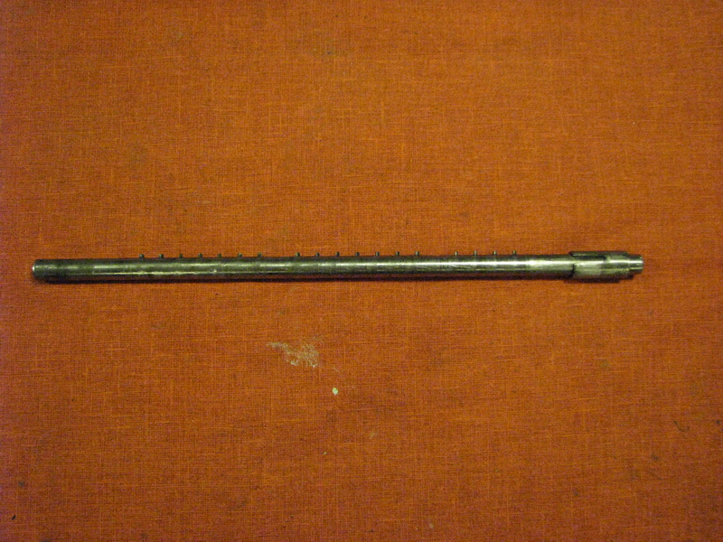
The hole on the right is original and used to pin a sleeve in place on the shaft.
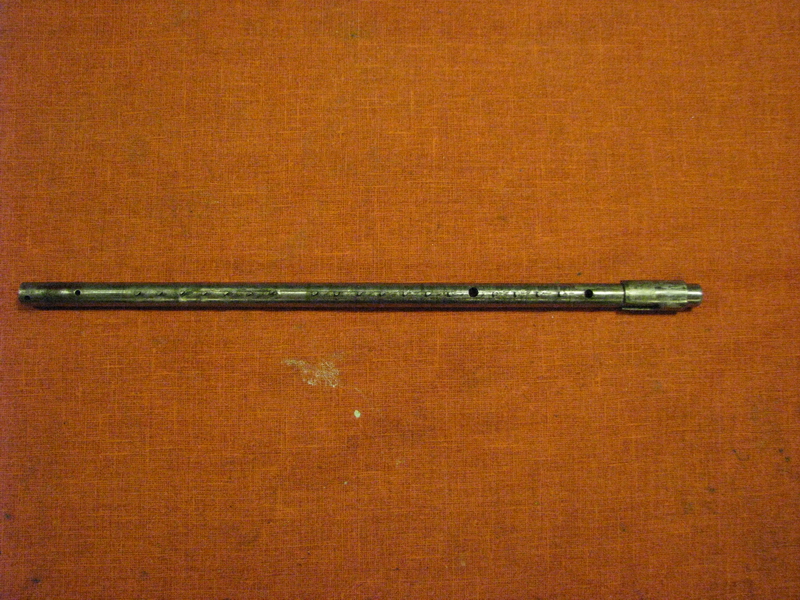
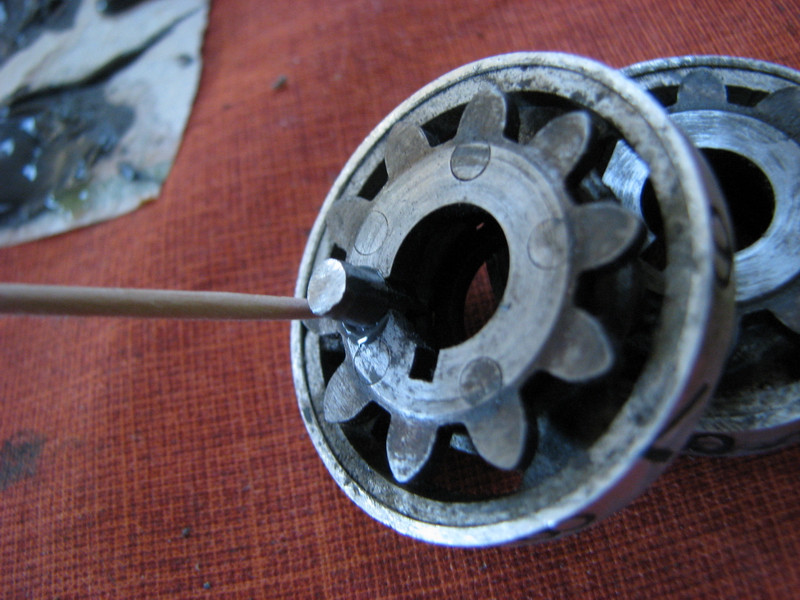
Since the machine will only see very light use from now on, I decided not to use a hardened pin. I turned a 6mm iron nail into a 4mm stub until it would go into the hole, glued it there with epoxy, and then started filing to reproduce the profile of the other clearing teeth, making sure to measure the distance around a teeth or 4, then locking the calipers and checking every few strokes of the file whether the distance on either side was correct yet.
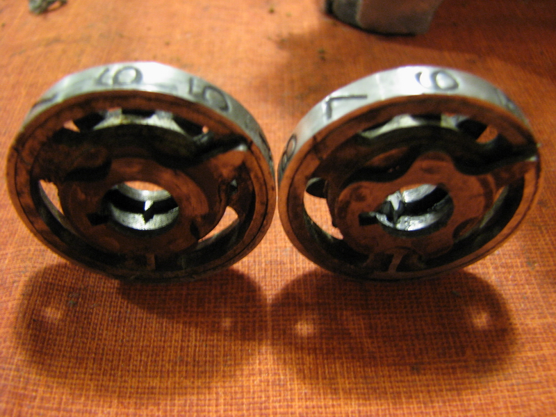
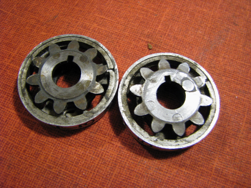
I ended up with a perfectly formed clearing tooth in the exact location necessary, reassembled the shaft, and the offending numeral wheel would still not clear. This had obviously been a case of act first, then think. The original clearing tooth which I had drilled out had probably been fine in the first place. The problem was the numeral wheel itself. They have a wedge against which the clearing tooth is supposed to push. This wedge is made of steel, and inserted into a slot in the cast body of the numeral wheel, before the gear is riveted to it and the outside aluminum skin pressed over it.
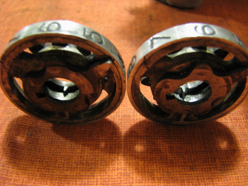
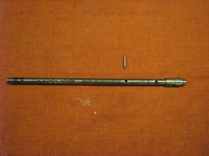
There is essentially no sensible way to replace it if it breaks off, which of course is what it did in the offending numeral wheel - after removal of the shaft, the numeral wheels are only held in place by sprung catches, so they are easy to remove. As soon as I took it out, the broken wedge fell out. The only solution is to come in from the side, as the pictures below demonstrate.
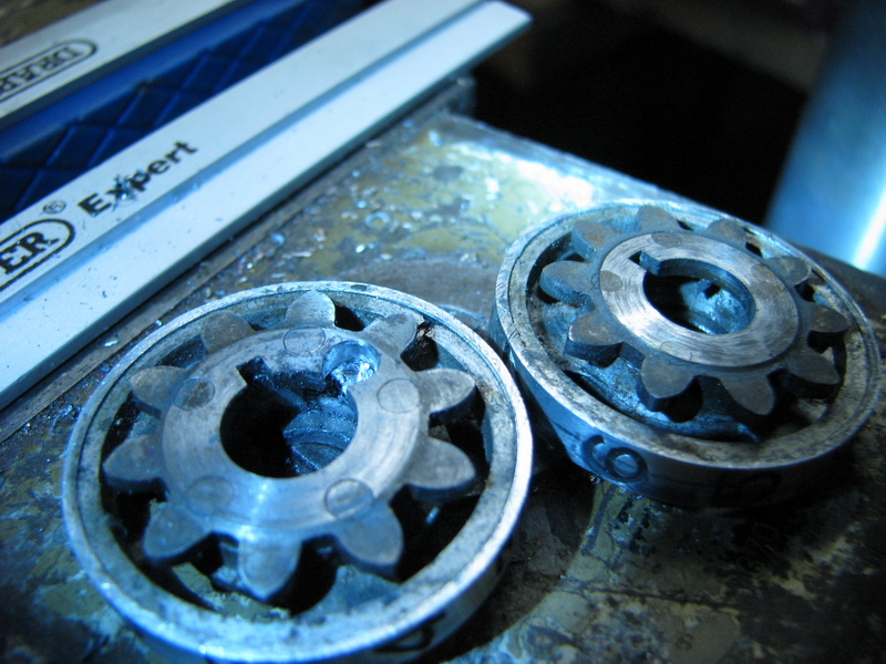
A similar technique with a 4mm drill and a 6mm nail turned down to fit was employed, and some careful measuring got it to the exact right profile.
There were then some small issues reassembling the registers (I originally planned to put the wheel with the replaced clearing wedge in the 13th position to make sure it wasn't used too often, but it turned out that the 13th numeral wheel is different, so the tens' carry tooth for this numeral wheel was in the wrong position, which blocked the entire register on the first attempt to clear it), but in the end it all worked out, and I got everything working again.
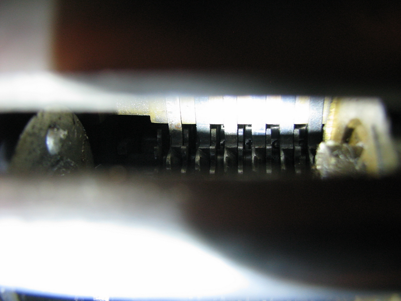
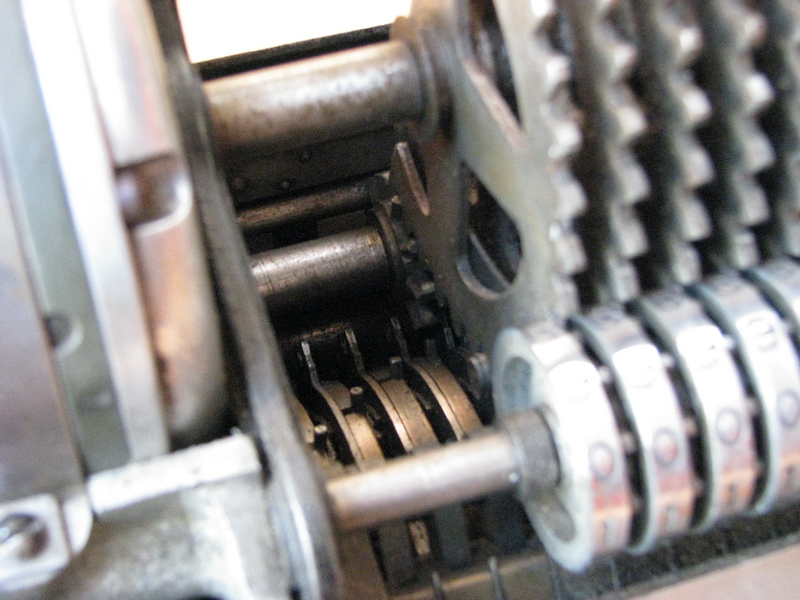
Since the result register is actually above the pinwheel cylinder, the register is constructed upside down with respect to its position in normal Odhner machines - the spring catches are at the top, and the tens' carry parts are at the lower back of the register - here they are, glimpsed from the back ...
The sprung retainer arms for the totalizer, with the top part of the tens carry arms for the register at the top of the picture:
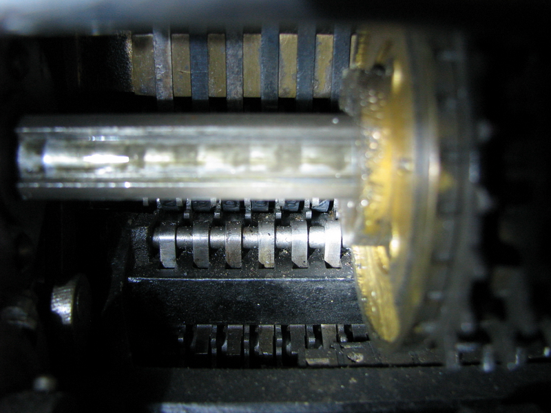
This is where the pinwheel cylinder lives:
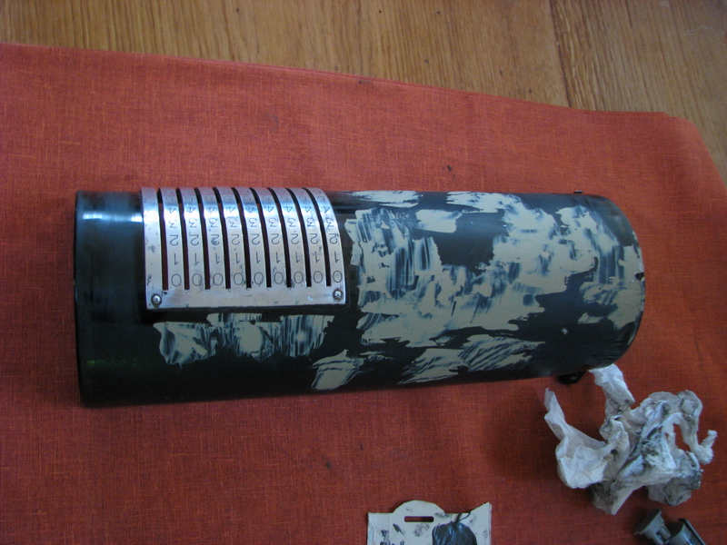
Now there were two more issues to attend to. First was the paint on the top cover, which was very ugly. The cover is aluminum, which swells when oxidising, cracking, breaking and bubbling the paint. Since the top cover was the only part affected, and since this part also carries no lettering or decals, it was an absolute no-brainer to repair and repaint it. All the oxidation below the paint was scratched away with an old screwdriver, and then the lengthy process of filling the resulting holes with car body filler could start.
Even the best car body filler shrinks a little on drying, so it took 3 sessions of filling followed by sanding, before I was satisfied enough to try and prime the cover with grey primer.
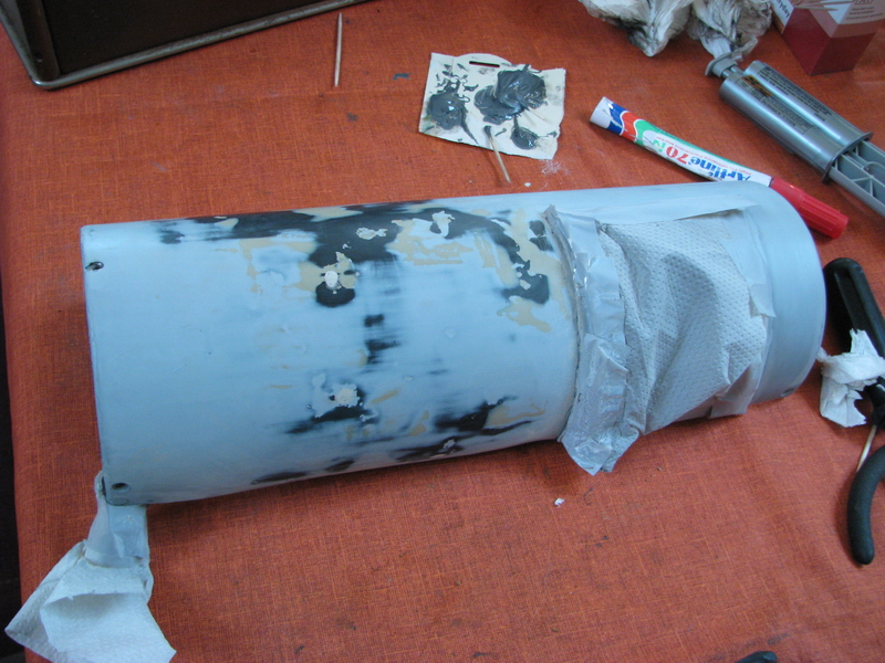
Sure enough, all the edges showed up as clear as day, because the absorption of the filler is different than that of the paint - so more sanding and priming, filling, sanding and priming,and sanding and priming ... until I felt satisfied for the cover to receive its first coat of black paint.
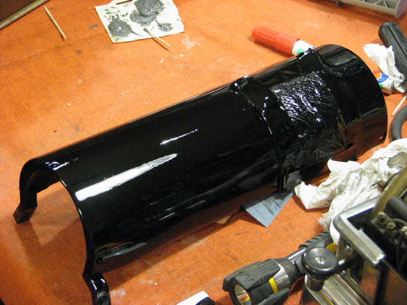
I warmed the paint so it would flow well, and I also warmed the cover in the oven.
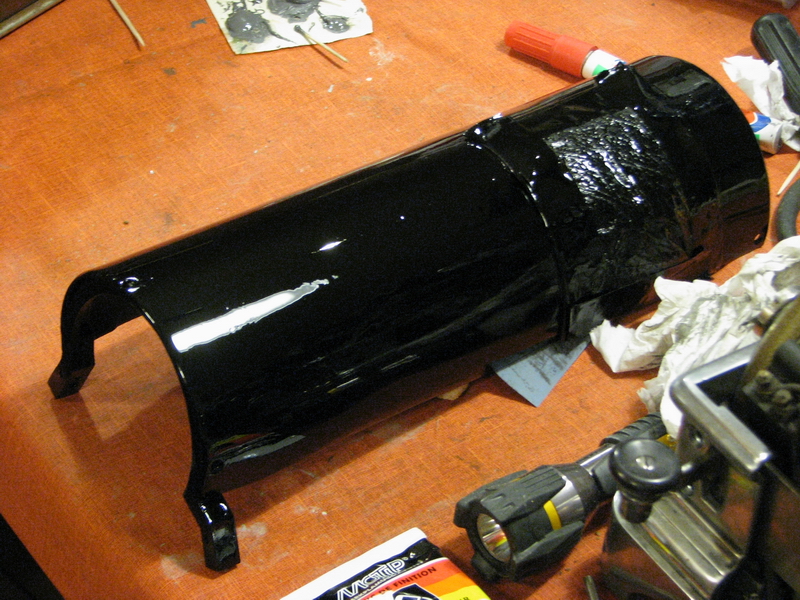
The first thin coat looked satisfactory, so I thought I would give it a good bake in the oven after a few hours to really set it. Unfortunately the filler and primer hadn't quite dried out completely, so everything crackd and my new coat of paint suddenly had plenty of chips and holes. So back to square one - filling, priming, filling, priming, sanding, priming, filling, priming, sanding, ... in the end I finally got there. The paint is not absolutely perfect, but it looks as if it has always been there, and that is the objective of a good restoration. The unsightly bubbles and holes are in any case gone.
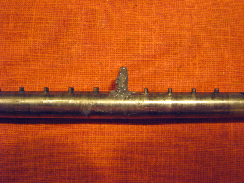
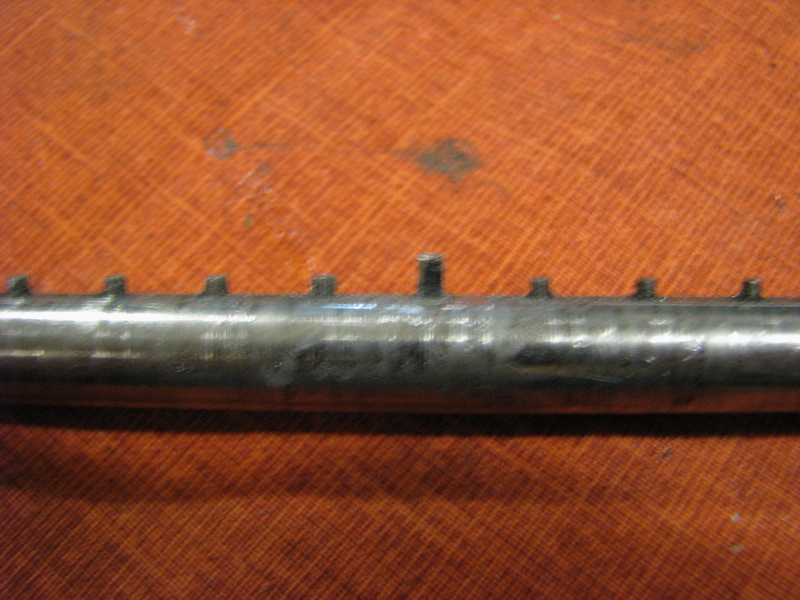
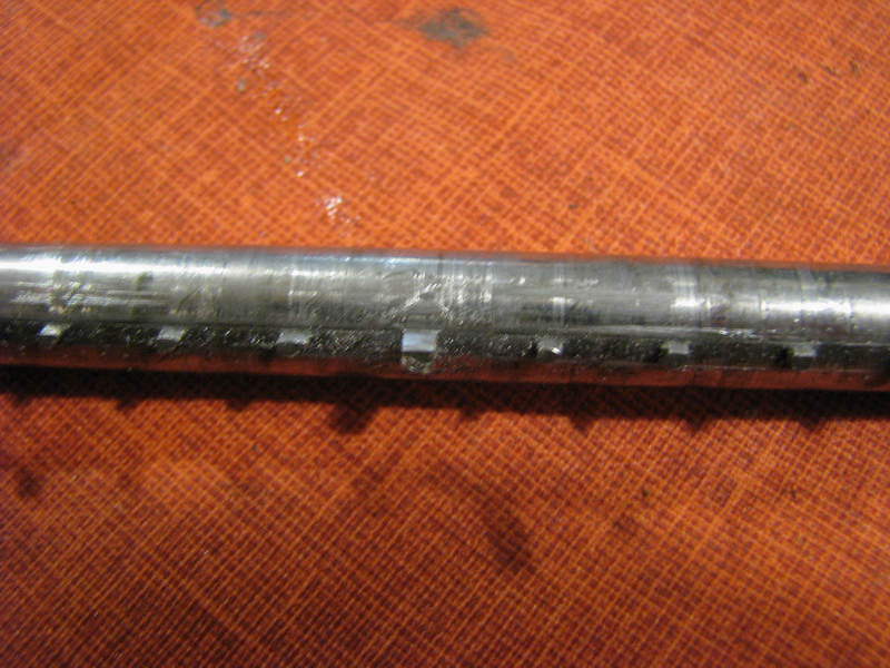
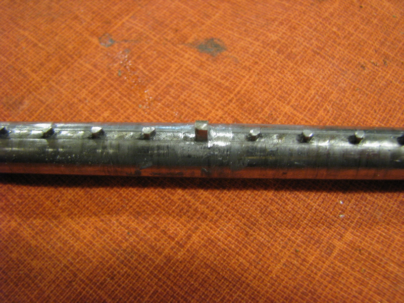
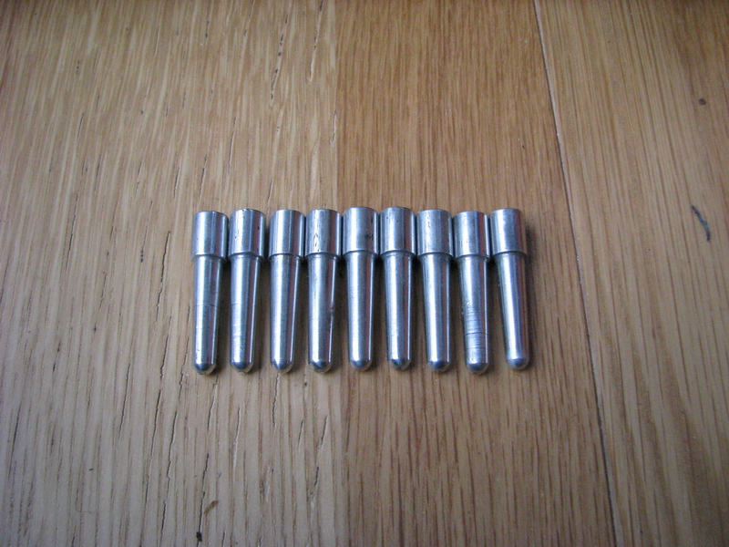
The second issue that remained was one of the input pins. They have an aluminium cover or shroud, and at some point one of these went missing and a replacement was fashioned crudely enough to be noticeable. I first tried to clean this replacement up but quickly destroyed it (correcting a taper already turned to the right diameter at the top obviously needs a lot more lathe-operating talent than I currently have ...)
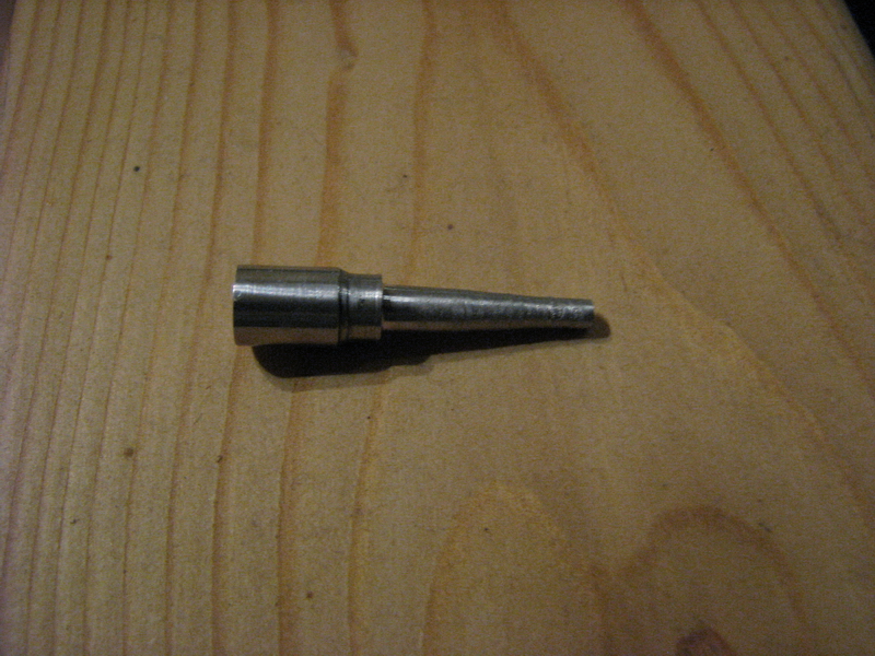
I just ended up making a replacement out of aluminium bar stock. See if you can spot it ...
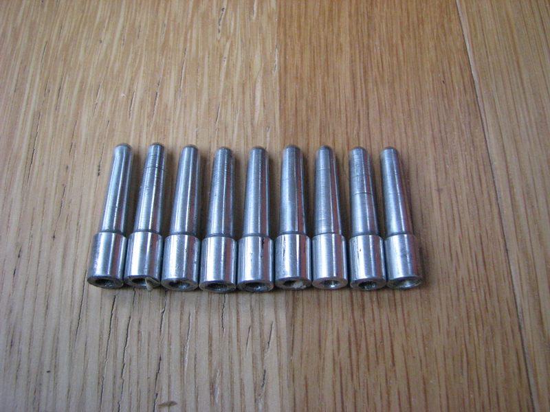
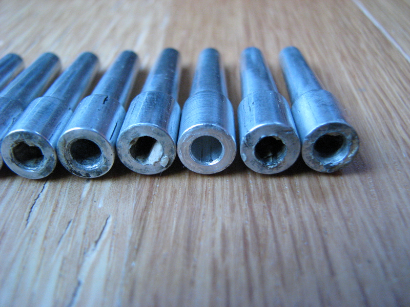
...the lack of putty gives it away.
Now, stop division. You set the dividend in the setting register, but do so on the right hand side, not on the left, as is usual in pinwheel machines. If the dividend is less than 5 digits, you can shift it to the left by a few places until the first digit occupies the fifth setting column from the right. Now shift the main lever to position 7, push and release. The machine will do one cycle, and the dividend will appear at the very left of the result register. The counter register will be on "1". Since you can't individually clear the counter register, put the main lever in the rest position, and clear the input manually. Now push the button on the bottom left for subtraction, move the main lever back to 7, and push down once. As soon as the cycle starts, you can release the subtraction lever as well. The counter register is now back to zero. Put the main lever back into the rest position and set the divisor in the input register, in a position where you can reach the first digits of the dividend. Now move the main lever to "7", press the subtraction lever, and push down. Keep the lever there until the bell rings, then release. The machine will do one more cycle and stop. Push once and release to cycle back. Now move the lever to "6", push the subtraction lever, push and hold the main lever until the bell rings, release, push once, move to "5", etc etc. Easy and quick.
The machine is even more amenable to "building up the dividend" because it avoids the annoying clearing step of the counter register. In this case you just set the divisor, and sum it until you reach the dividend. In this case there is no automatic warning when you overshoot the target though, so you need to keep a close watch on the numbers.
Incidentally, the "annoying clearing step" can also be avoided if you just remember where the one is, and mentally subtract it from the quotient.
Then finally, the portrait of the machine, and some video of its operation.
During the video it became clear that one of the tens' carry pins was stuck, and thus the second input pin from the right would count 1 more than it was supposed to do. The pin had probably become unstuck at the inside of the pinwheel cylinder, by way of its retaining hinge pin getting loose. This also results in the spring getting loose. The pin was then slung outwards and got damaged and bent. I have looked really hard, but I see no practical way of taking the machine apart so far that I could reach the inside of the pinwheel cylinder to effect a repair. Apart from having to take the entire machine apart, both on the left and the right side of the axle on which the pincylinder slides, parts have been pressed onto the axle, then drilled at the edge of the axle, and pins driven in. We're talking about the entire gearbox of the machine on the left hand side, and three cams on the right hand side. This is pretty much impossible to get apart without destroying at least some of these parts. It does mean that the machine miscalculates for now, until I can think of something. I managed to tap the hinge pin back in and the pin is now indeed stuck in the correct position, but there is no spring and it is too short, because part of it has broken off. I have in the mean time managed to drill a 1mm hole into the end of the pin, in which I will tap 1.4mm thread. Once that works out, we'll take it from there. I have some confidence that I will be able to get it working, even if it is by doing a makeshift repair.
And finally a video of the machine in action: