
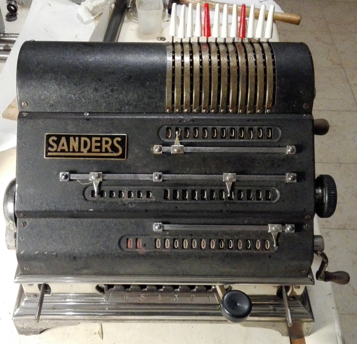
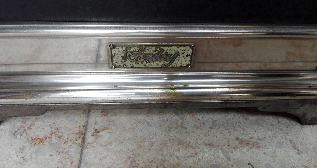
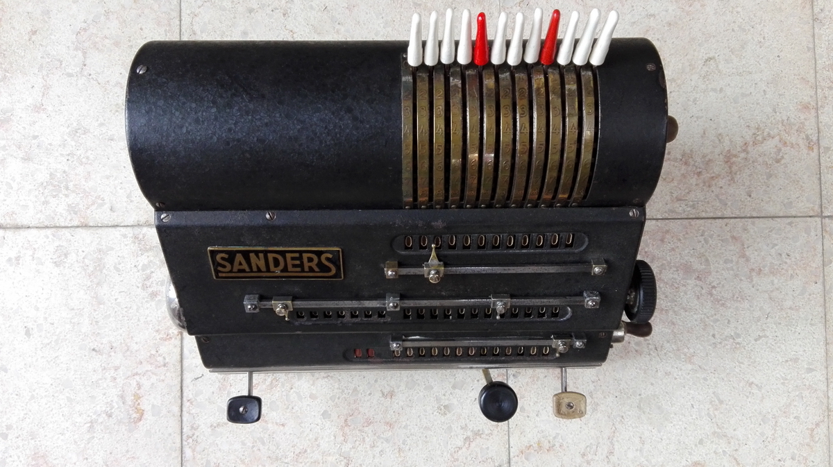
Sanders Calculating Machine
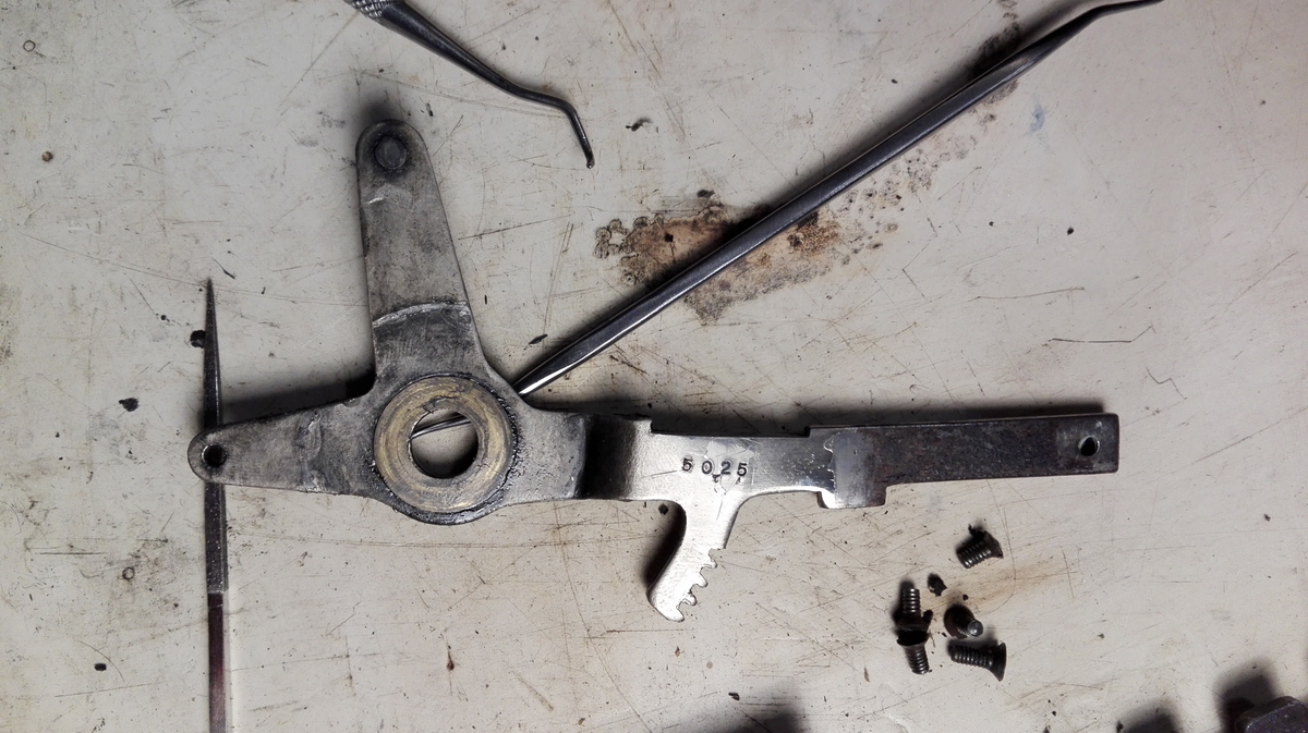
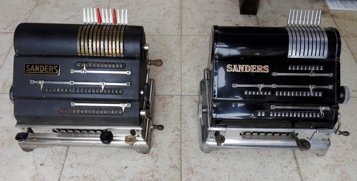
As opposed to my own example, the machine in the Arithmeum is an early Sanders machine.
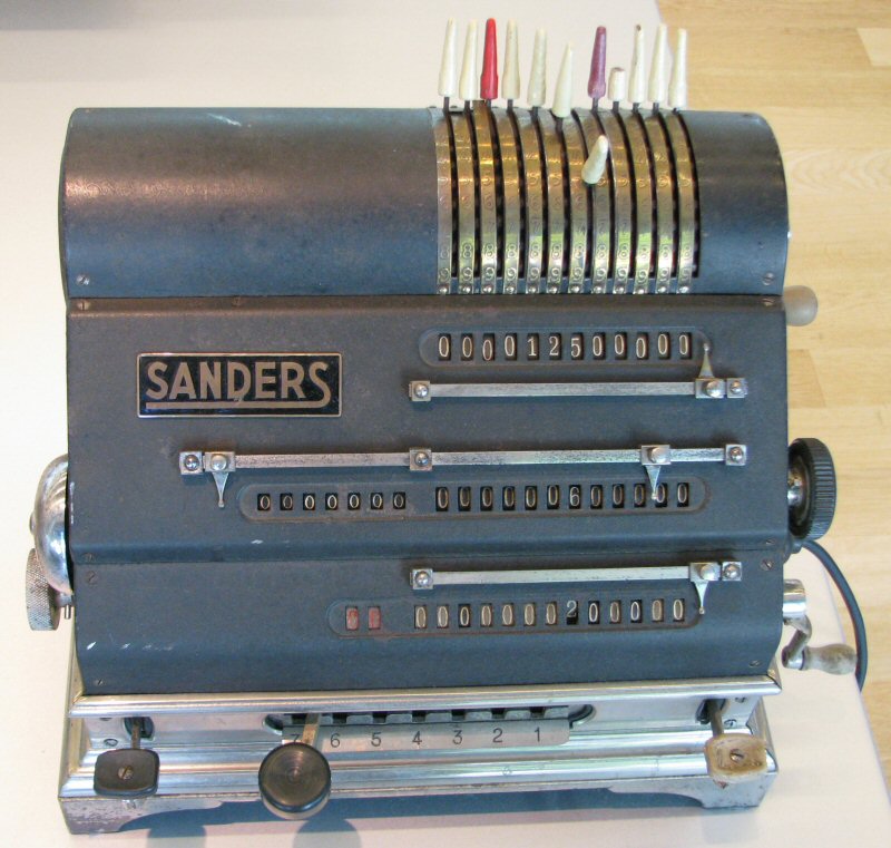
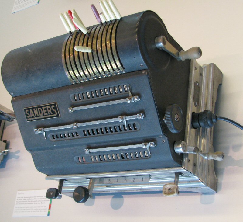
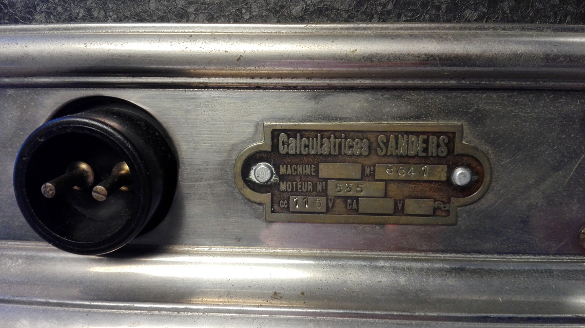
Its serial number is 5025, mine is 18301.
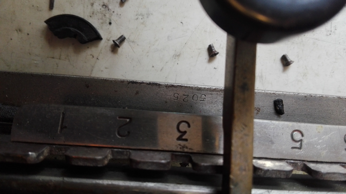
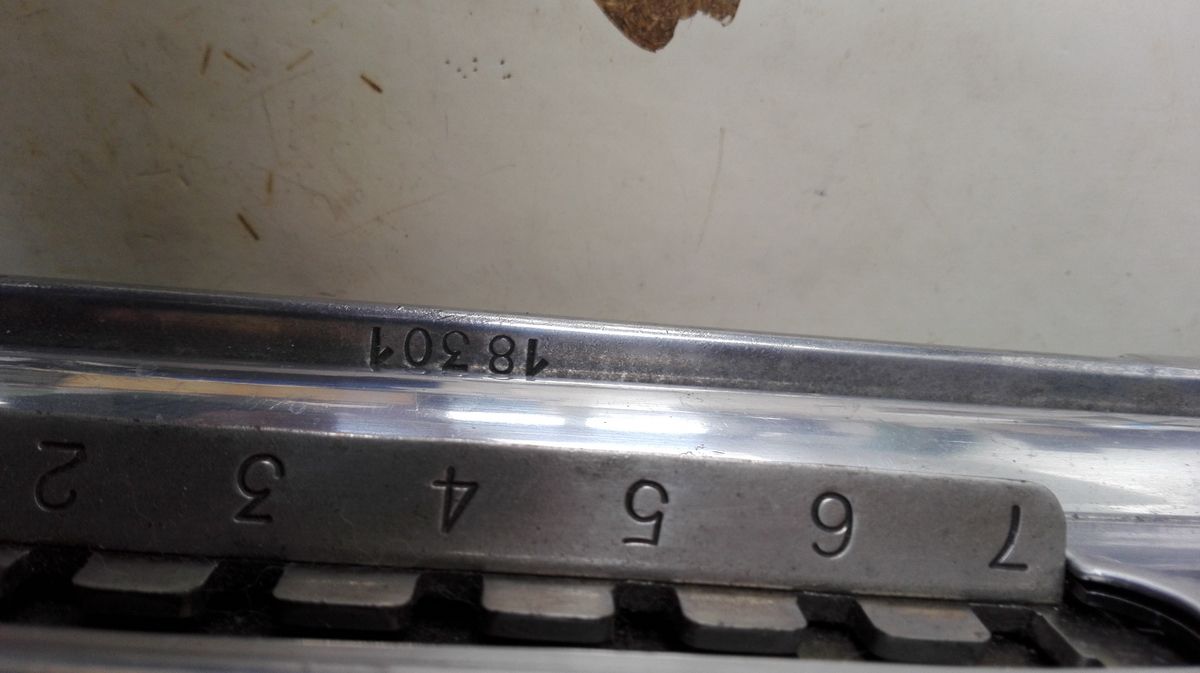
Now, I find it hard to believe they would actually have built 18000 of these machines, so the numbering ranges will probably always remain a mystery.
The fact that it's early also means there are a number of differences with my own machine:
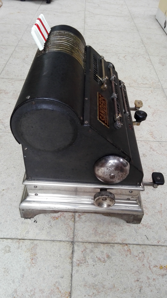
All of this makes the machine very similar to the earlier Eclair, which as only different feature has the base made out of wood.
Now - what seemed to be the matter ?
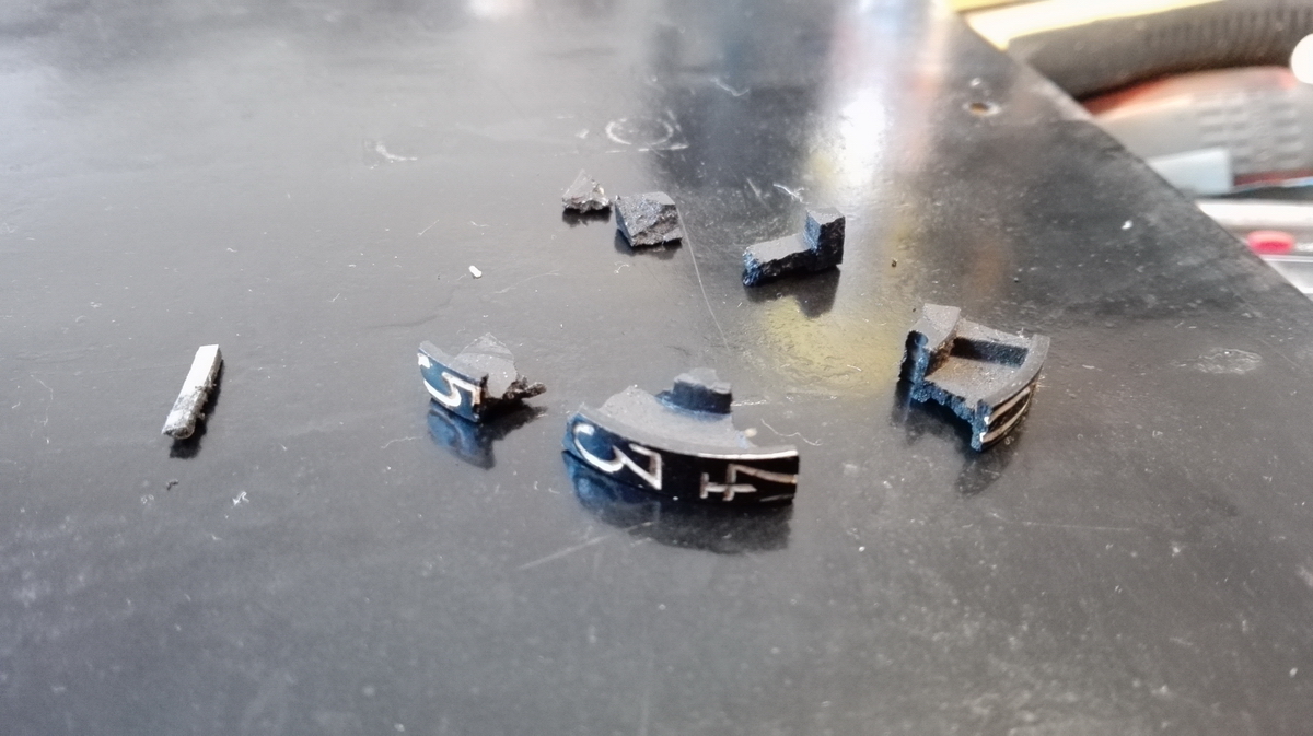
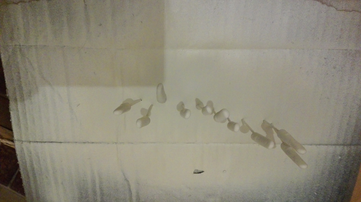
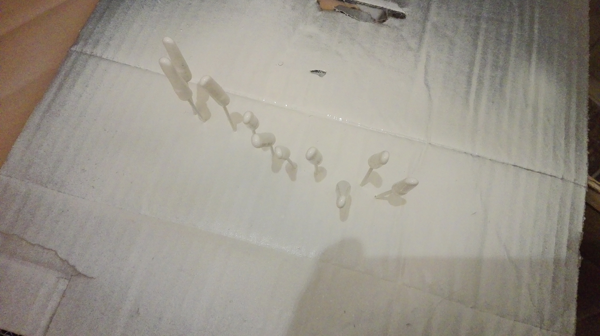
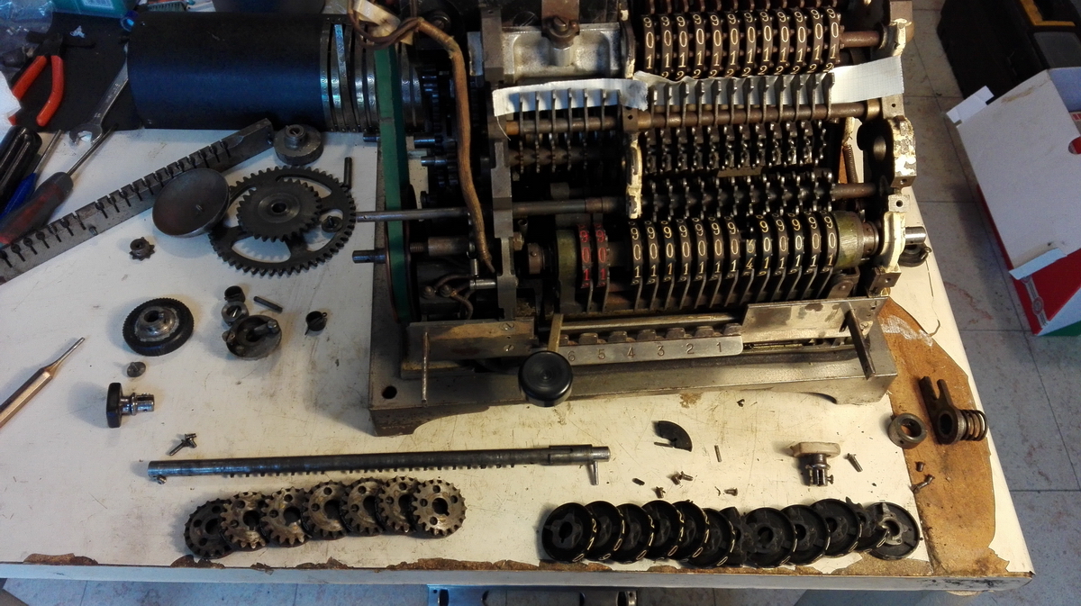
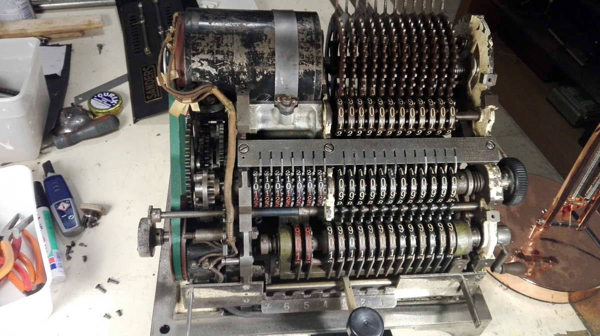
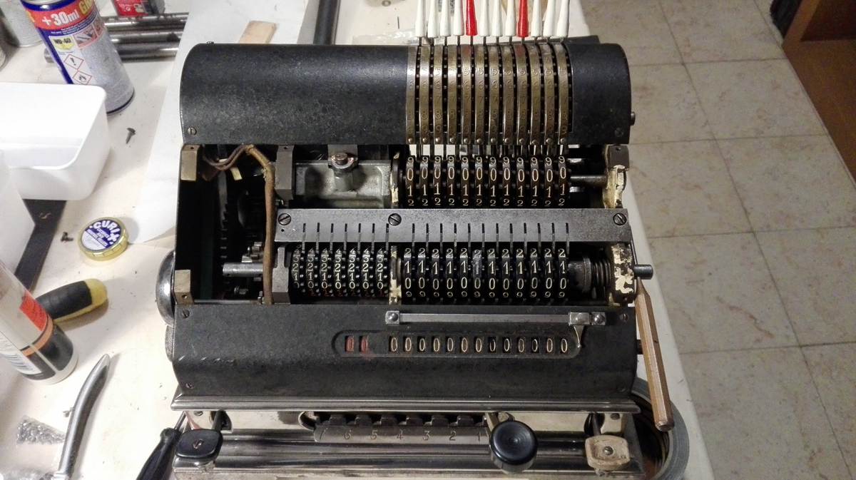
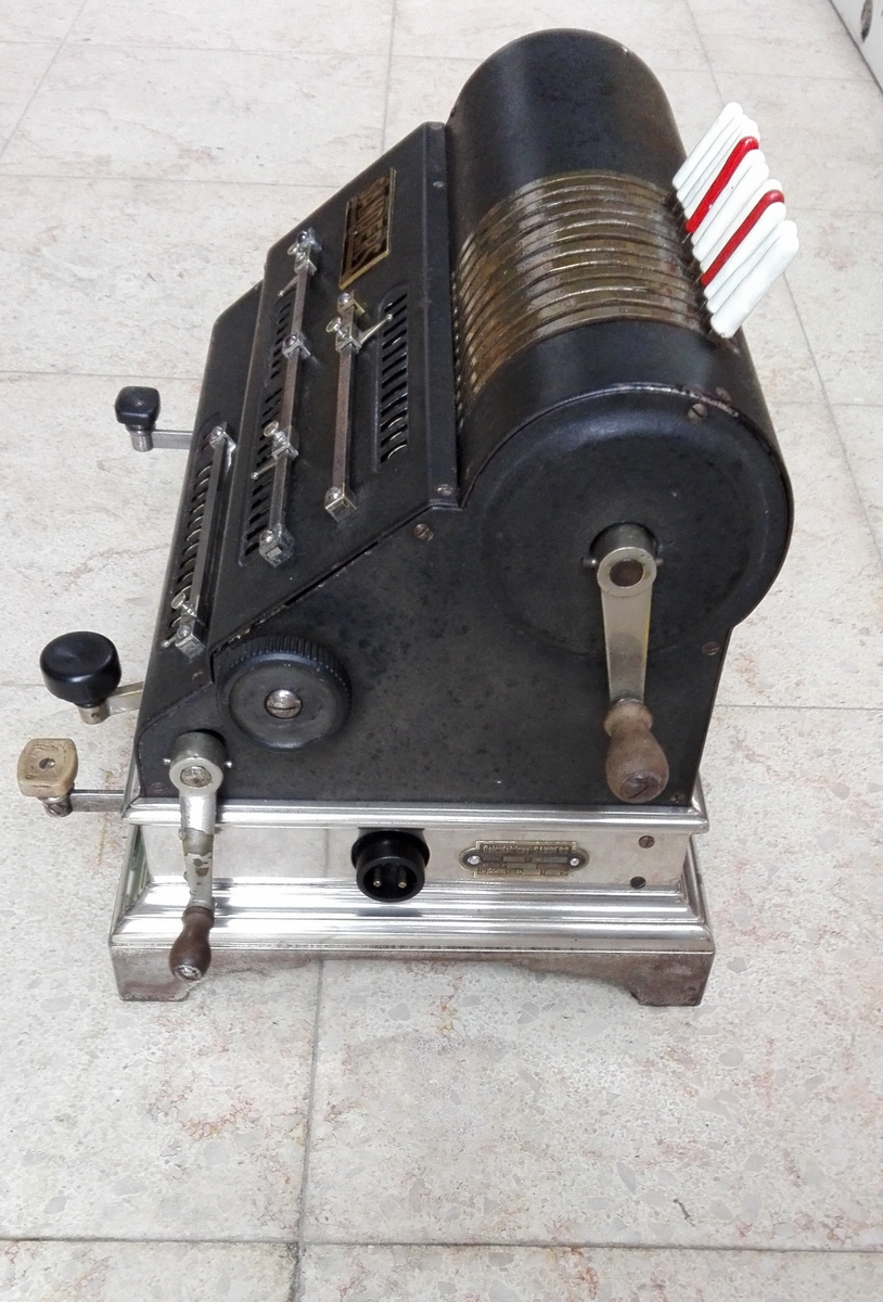
The machine was obviously blocked. Taking the covers off, it was also obvious that at least three numeral wheel had breaks and parts were missing - two in the result register, and one in the accumulator. Fragments of these wheels could be found on the bottom plate of the machine.
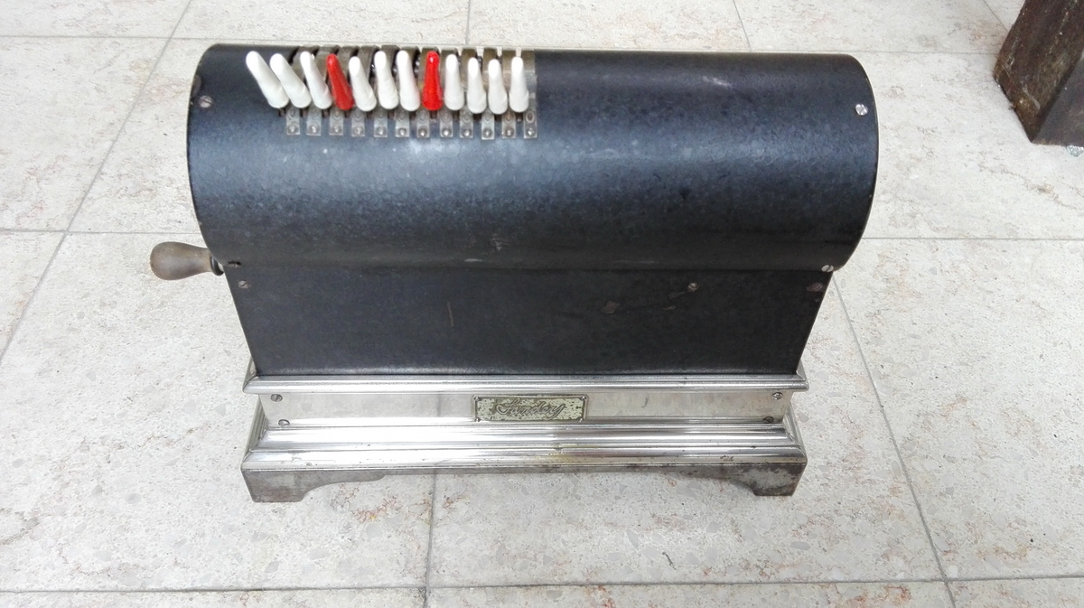
Three of the input pin covers had been broken or replaced earlier with bad replicas.
In addition, somewhere in the past, this machine must have been completely rebuilt, and on that occasion the frame, as well as the input pins had been slathered in the same thick cream-colored paint.
Further undressing of the machine showed that there was quite a bit of dirt and rust, and that the entire spring mechanism for the bell was missing.
The blockage of the machine was due to two things - firstly, the broken result wheels were preventing the machine from completing its cycle and return to zero, and secondly, the main handle of the machine was slightly bent downwards, so that a large amount of force was needed to push it all the way to the right and bring the machine into the setting position. Once these things were remedied, and the lever was bent up a little, things went well.
Four further things needed to happen: 1. cleaning up the rust and dirt as well as possible. 2. remaking the missing input pins and removing the hideous paint blobs from the ones that were still OK 3. checking the electric part and the motor - does it still work ? 4. The main issue - fixing the broken result wheels.
Cleaning and polishing is a long but satisfying process, and there weren't many surprises there - whatever I took off the machine was cleaned and put aside for reassembly. The base and covers were cleaned up, and since disassembly of the input section of the machine proved to be impossible without drilling out a very large cotter pin, I had to be satisfied by just cleaning up the rust on the input sectors with brushes and abrasive paper - taking care of course that nothing would get into the pinwheel cylinder lurking below...
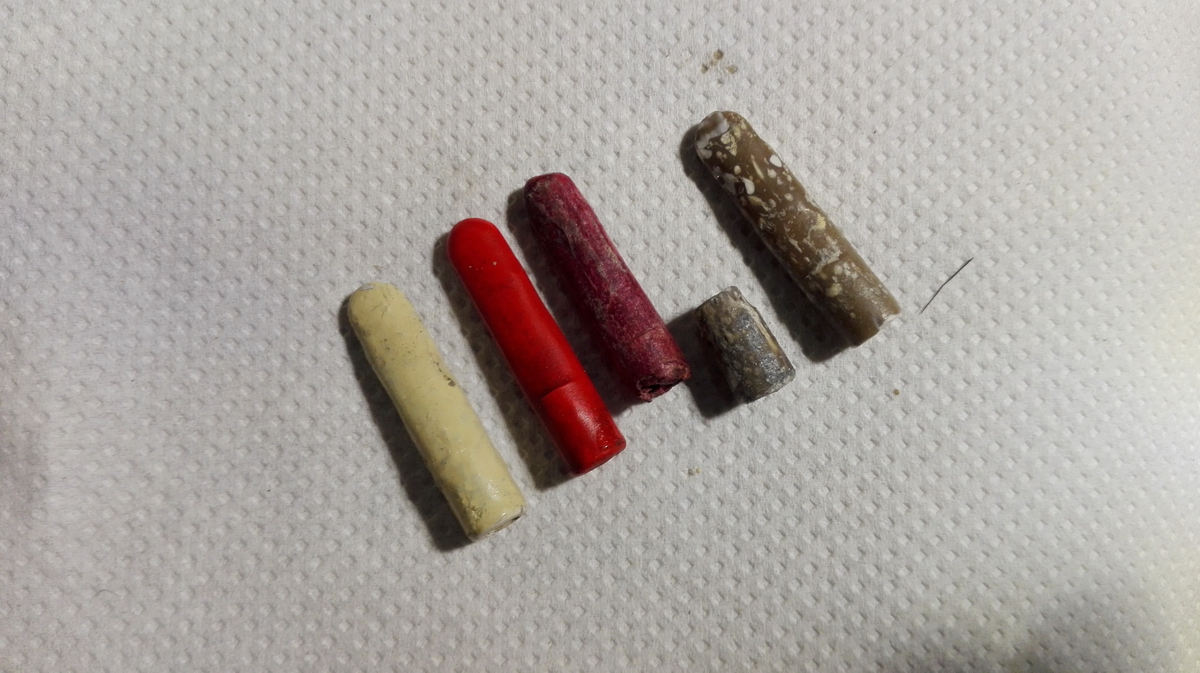
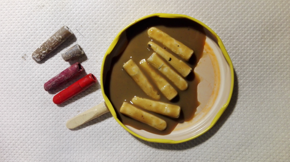
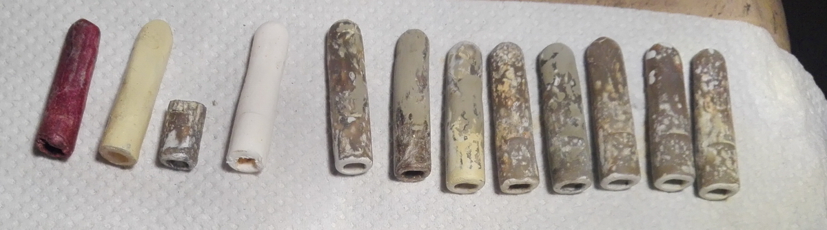
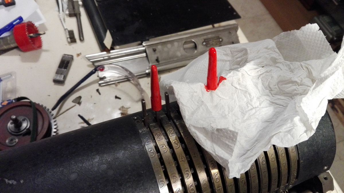
Remaking the input pins and taking the paint off proved a little more challenging. I decided to go with a mould of the red input pin, since that was relatively intact and especially unpainted, so its surface was smooth. I molded it into silicone, and cast a few replacement input pins, three white and one red. After a quick trial on one of the remaining pins, which proved it was impervious to my favorite paint stripper, all the painted input pins were dunked in stripper, and the result wasn't pretty.
The pins turned out to be dark beige, white filler was used before painting them, and they were full of chips and holes, which I had to fill with car body filler to smooth them out.
After plenty of filling and sanding, they were ready for a base coat of primer, more sanding and filling, and finally a few top coats of cream-white paint.
Even though I had coloured the resin for the red pin red, the colour didn't match the existing pin, and I decided to paint it as well to get a better match.
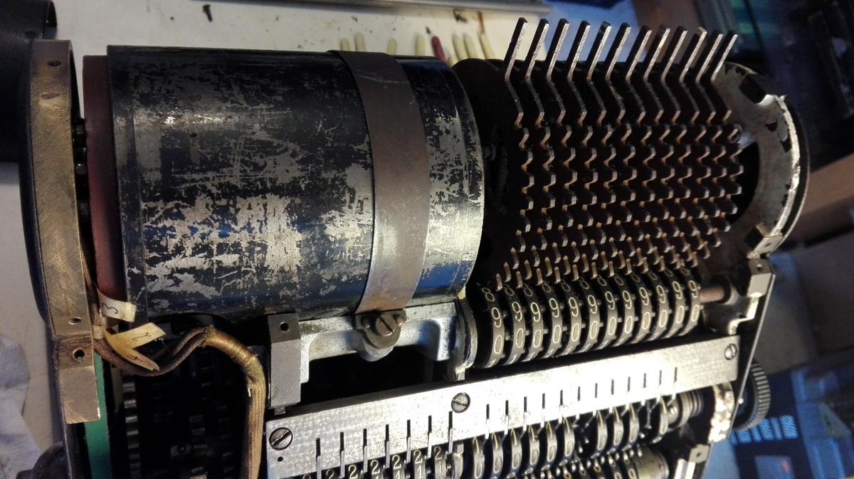
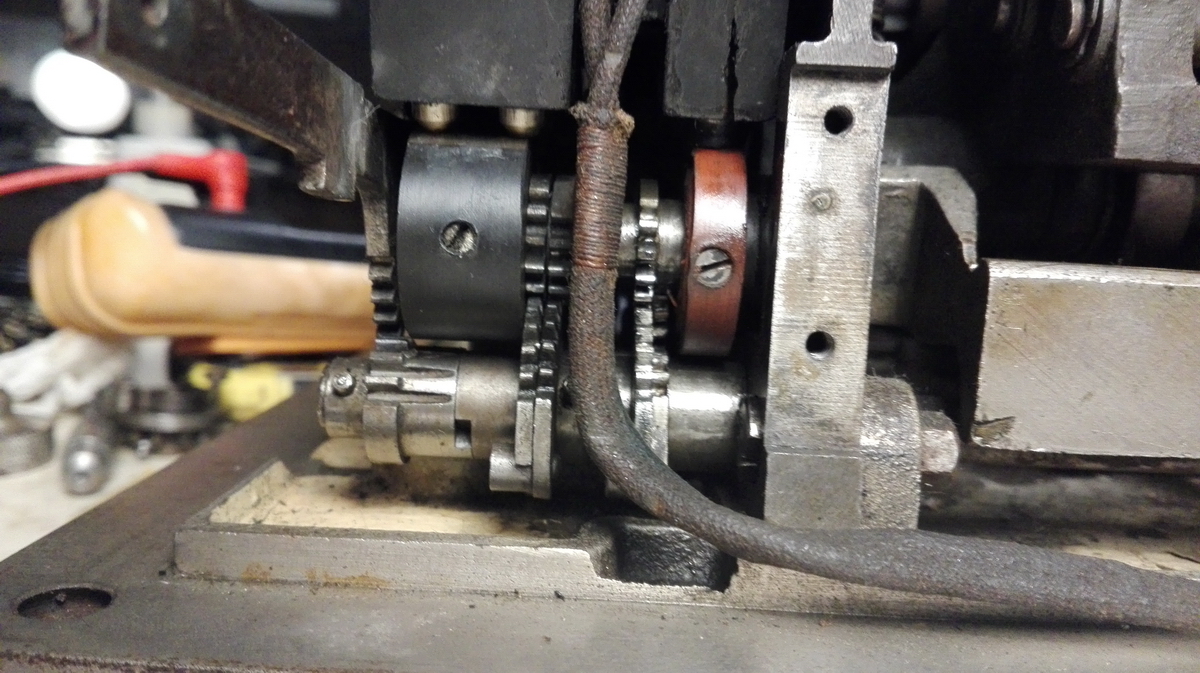
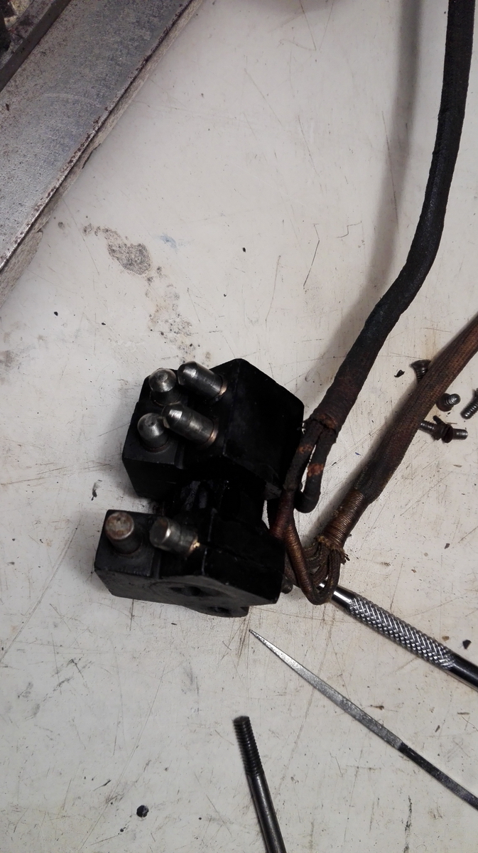
Then it was on to the electrics. I applied 110V AC on the plug, carefully measured that the frame of the machine wasn't under tension, and with the whole machine at zero, pushed the button down that should operate the motor after checking the machine was free to rotate by hand. Absolutely nothing happened. This taught me about the first of the two problems in the electric part - the selector rolls, which are rotated to provide various combinations of "juice" to the feeler fingers that branch off to the motor, were not working properly, because everything was dirty and stiff, so they had to be disassembled, cleaned, oiled and reassembled.
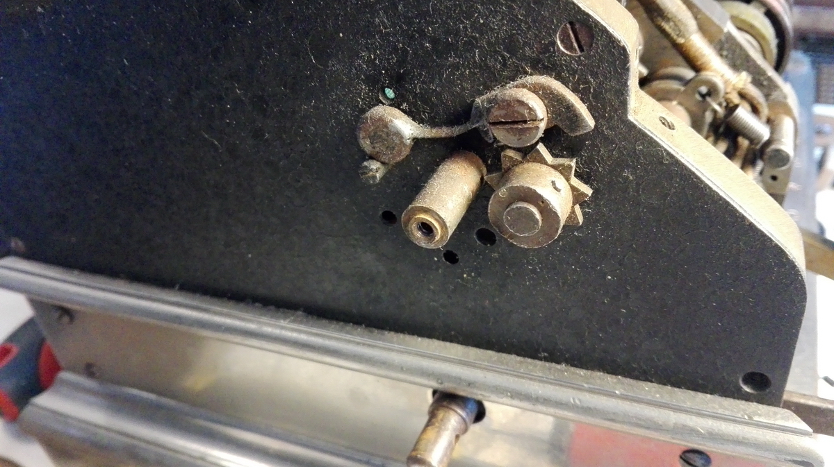
Disassembly:
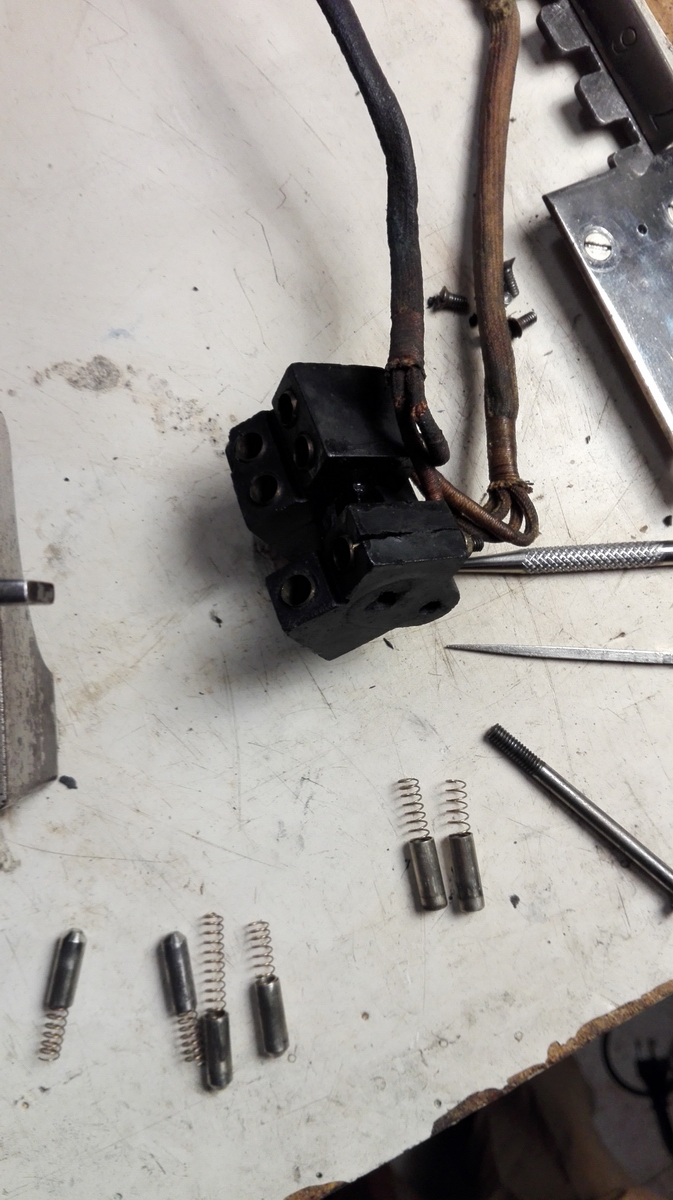
Reverse roll on the left, operating roll on the right.
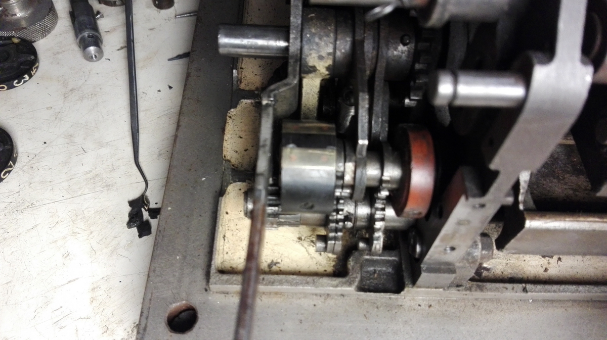
Operating roll operating:
Reverse roll reversing: (I know, I know, sorry ...)
These are the spring loaded feeler fingers:
And the operating lever for the reverse.
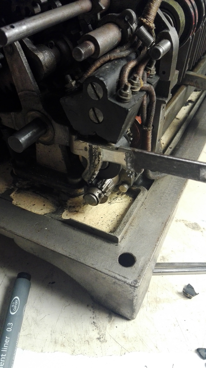
...which normally lives here. You can see the block with the feeler fingers is also back in place.
Taking all the electrics off the machine immediately provided me with the possibility to check the resistance of the rotor and stator windings. All seemed fine there, so after remounting all the electrics, I expectantly pressed the button. This time, the motor produced a low hum, and showed a very slight preference for rotating in one direction instead of the other. Not good.
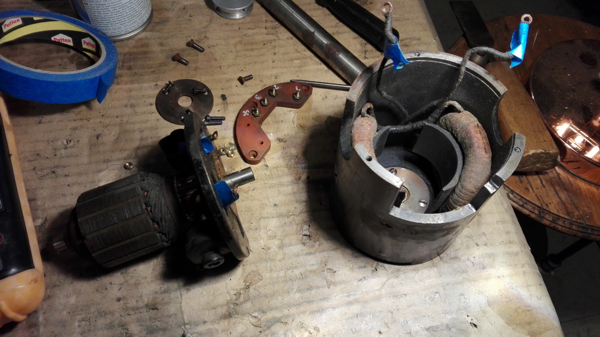
So I took the motor off, disassembled and cleaned it, and it finally slowly started to dawn on me that it was a different motor than the one in my own Sanders. I hd seen of course of the plate on the side of the machine that it takes 110V, as opposed to my own Sanders, which can be hooked straight to a 240V wall outlet, but what I had missed was that this "universal" motor was not tuned for using AC - it is apparently a pure DC motor. There was of course a clue on the type plate - CC 110V means "courant continu" - or direct current in french.
Luckily we have an electrical lab at university where they happily provided a 110V DC test voltage, and the motor ran beautifully. Problem solved, at least until we could test the finally reassembled machine.
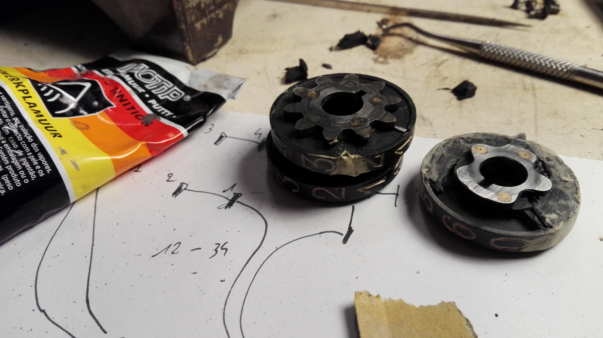
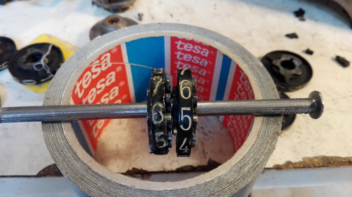
The last step was to attempt to reconstruct the broken result wheels. In the accumulator register, I got lucky, because the break was clean, and the piece was there. I glued the steel clearing tooth back in place, and glued the wheel back together. Fixed!
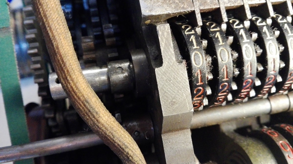
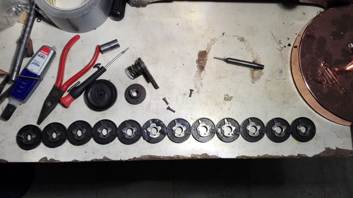
The same could be done for one of the numeral wheels in the result register, where there was only a small piece missing, that could easily be filled and painted once the register was disassembled for the last patient, a result wheel where three quarters of the circumference was missing and had turned into tiny fragments scattered on the base plate of the machine.
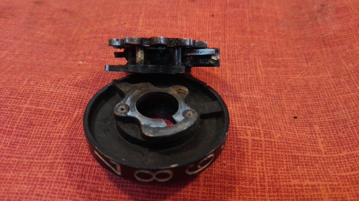
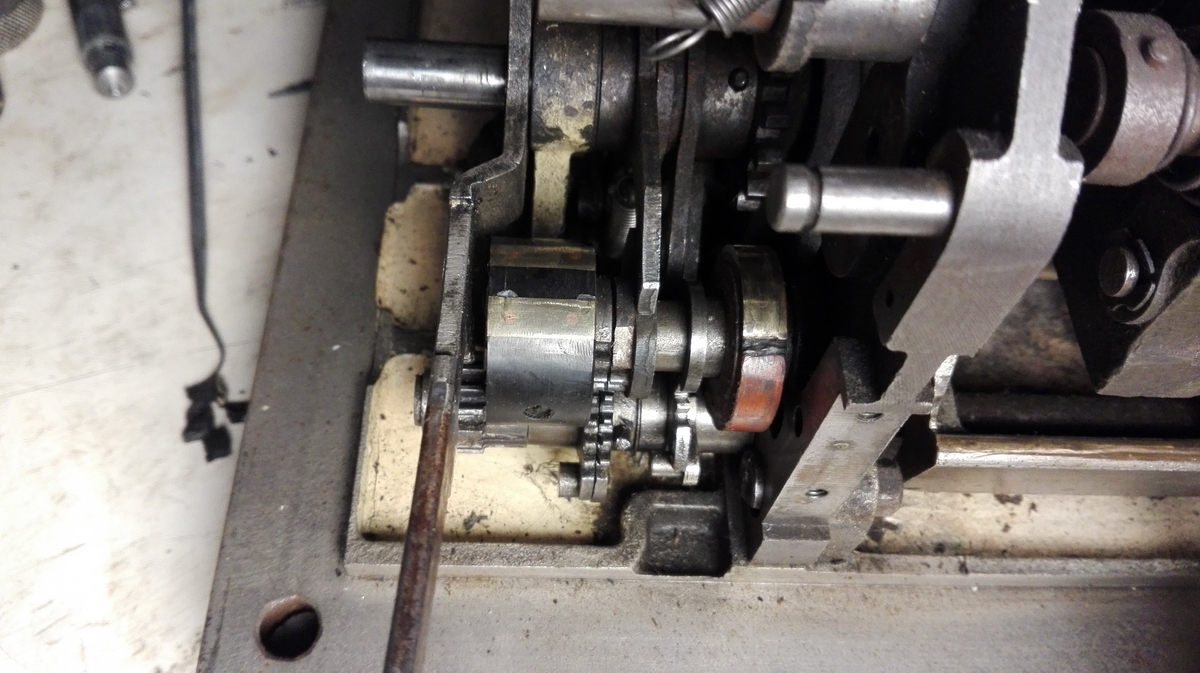
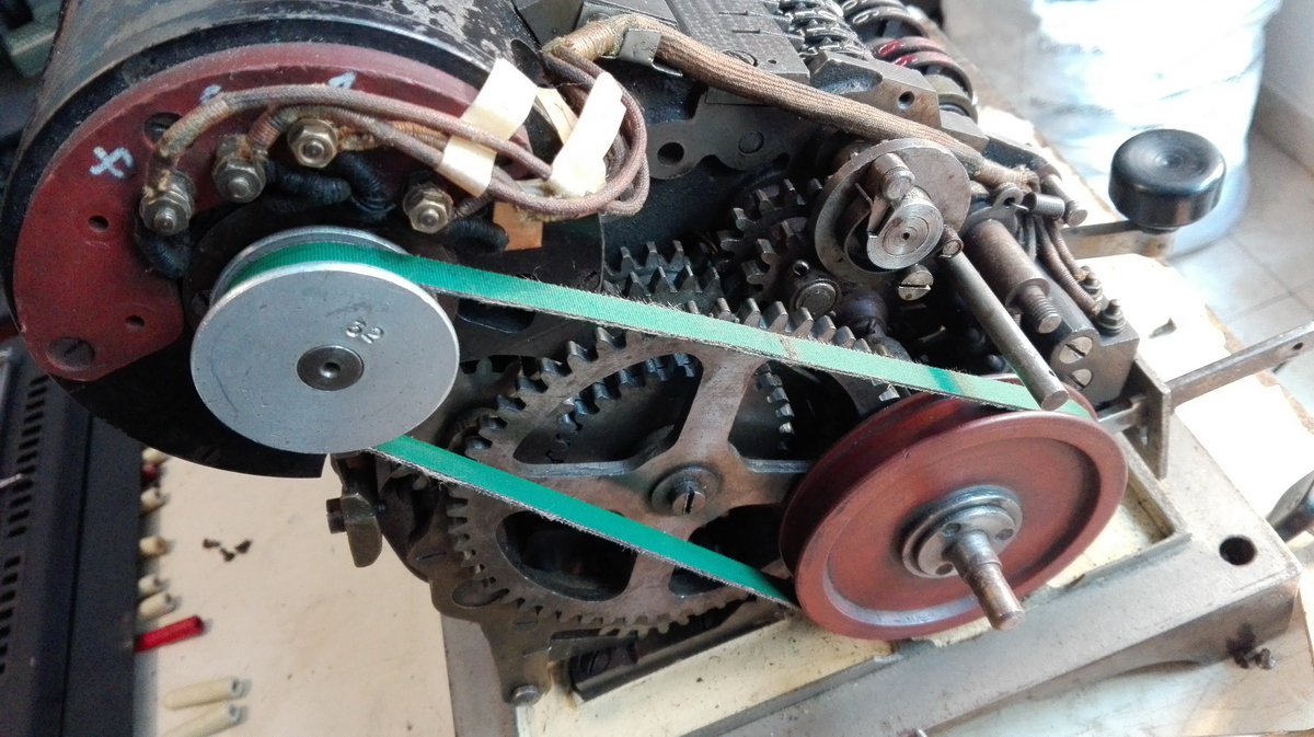
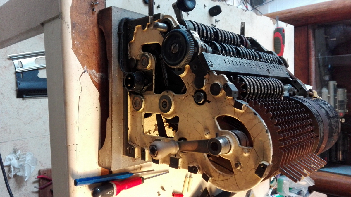
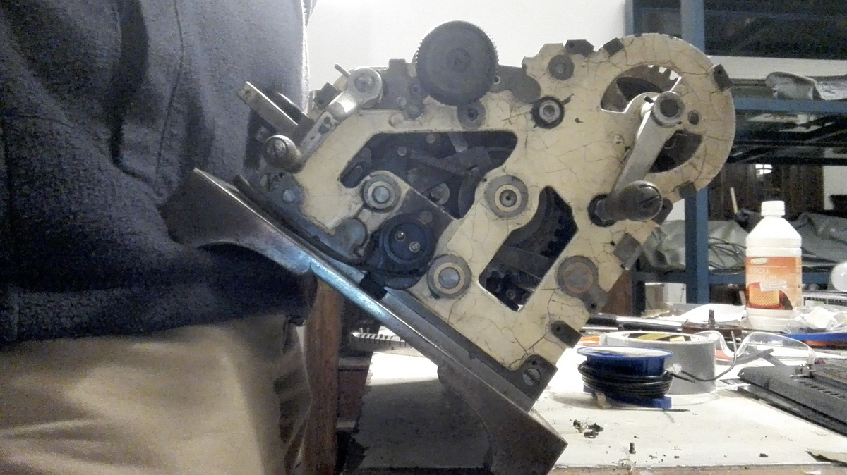
This would require some serious reconstructive surgery. Before I could start with any of that (or indeed get the wheels out to take the pictures above), the result register would have to be disassembled, and this requires to take most of the left side of the machine apart, in order to be able to take the pinned parts off the axle that prevent it from sliding through to the right.
Also the right side cover needs to be taken off, and that means taking off the three handles or knobs at the right of the machine.
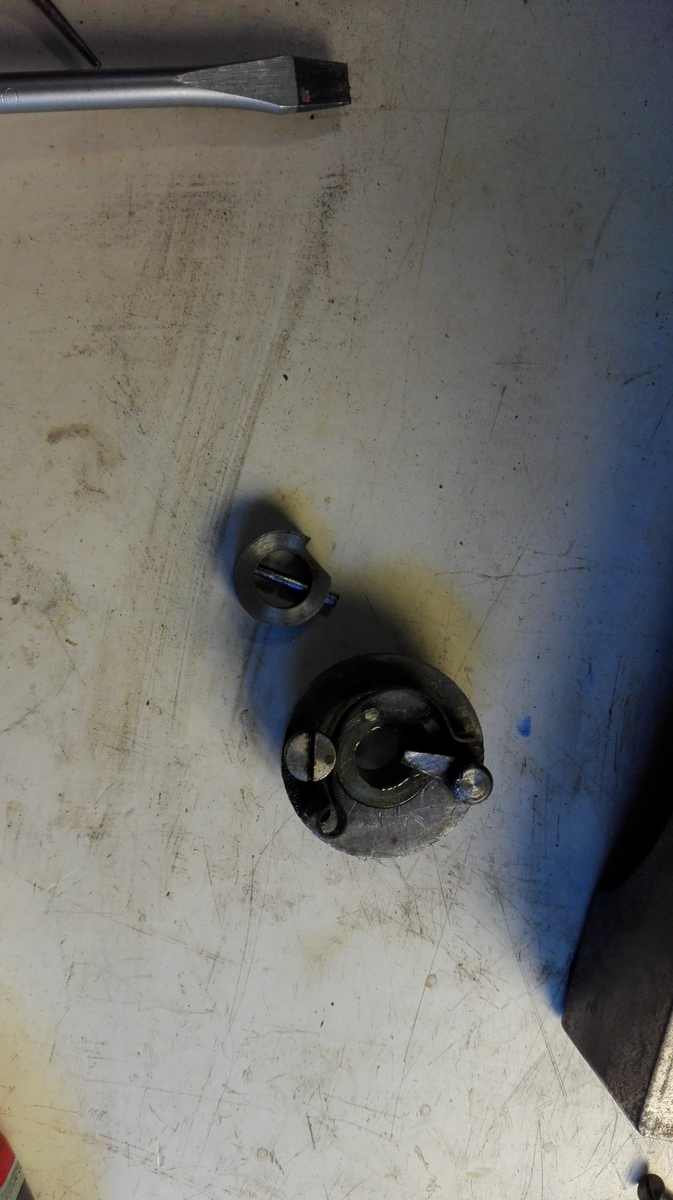
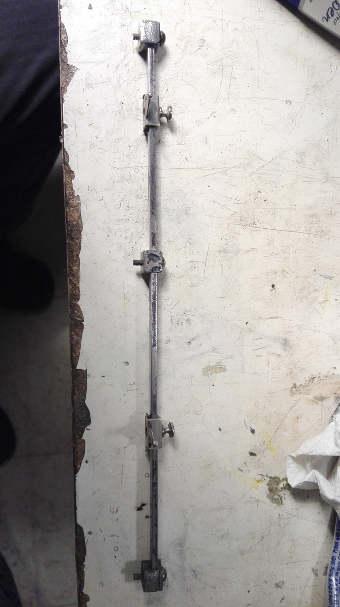
On the left, on the axle that needs to come out, there's a sleeve which also serves as a position lock, together with the ratchet pin that is on the collared gear that sits loose on the shaft, and then there is a pinned distance collar that determines how much the shaft can slide to the right when clearing. All of these are taken off.
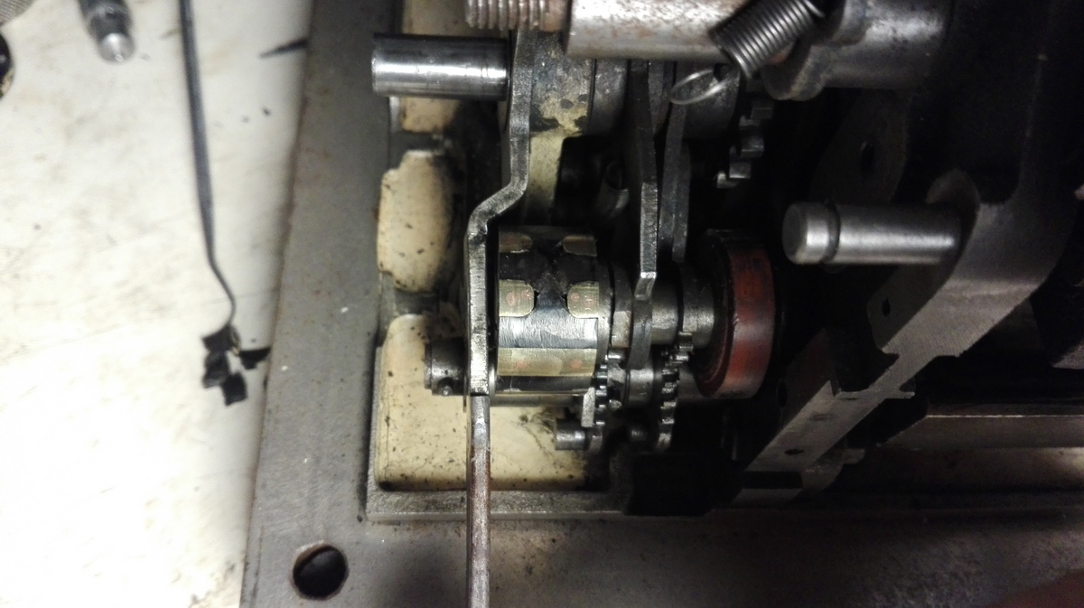
And then the fun starts. On the right side of the register, we have the notched distance collar for the tooth of the clearing knob to slide over, that is fixed with three screws.
This is taken out, and the right side of the axle is now free. On the inside of the frame, there are two more parts in the way - starting from the right, there is a sleeve with a spring, that is also an interlock to prevent anything else happening with the machine when the register is being cleared (there's a kind of fork sitting over aother axle that provides an interlock when the axle shifts to the right when clearing).
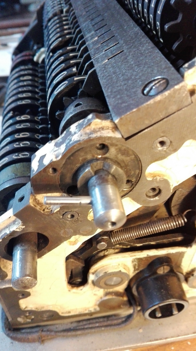
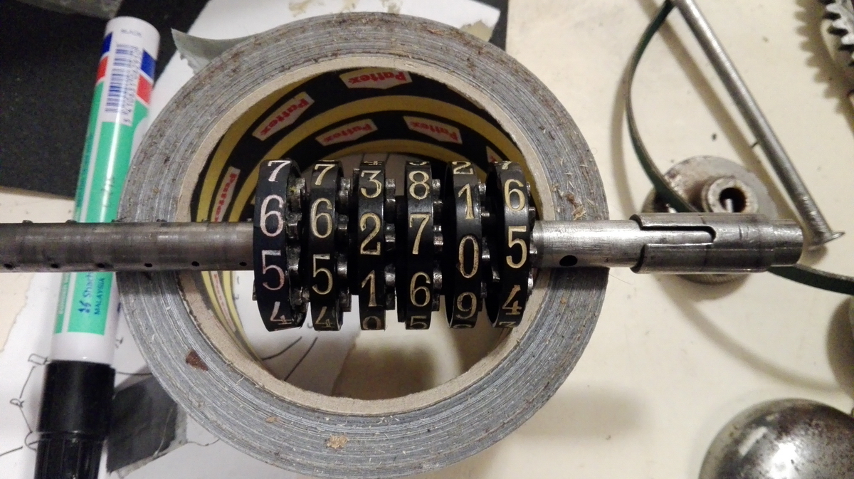
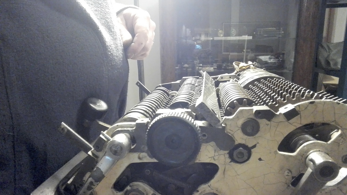
This part (and the round tubular piece to its rigth as well) are bored too large, and thus sit loose on the axle, but are centered by a second, smaller sleeve that slides over the axle and into the central hole in this part (you can see this sleeve sitting at the right end of the axle in the picture above). The sleeve is notched, because to the left of this first part sits the other very simple tubular distance piece, that is however screwed to the axis with a pin that is threaded at the end and goes straight through both the part and the axle, screwing into the threaded hole at the back of the distance piece. The notches in the sleeve allow it to slide also past this locking pin/screw and all the way through this distance ring, and thus center it on the axle as well - the lock pin is straight and not tapered, so this by itself does not provide any location. Now in order to slide the axle itself out through the right, the clearing teeth on the axle need to be able to slide through a gap in the middle part of the frame, so that means that the assembly slots in the numeral wheels need to be lined up with this gap in the frame.
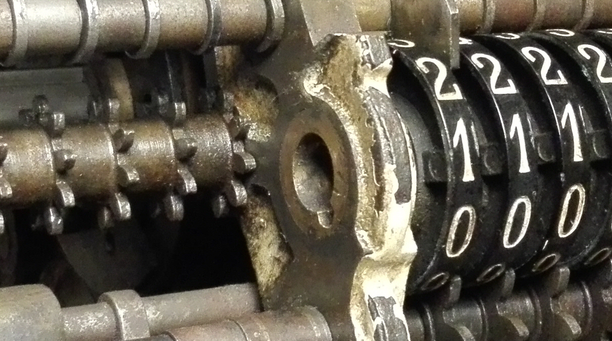
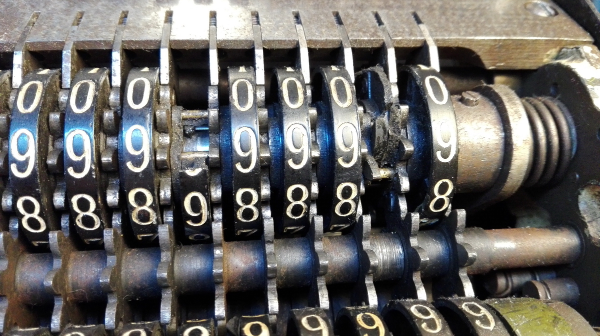
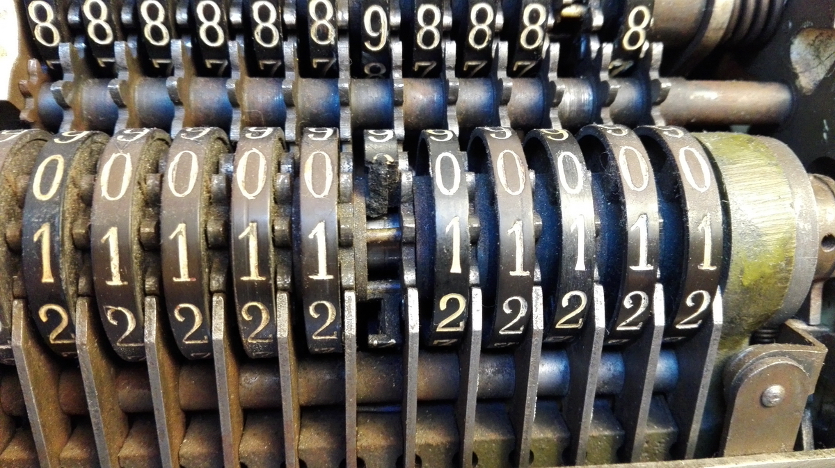
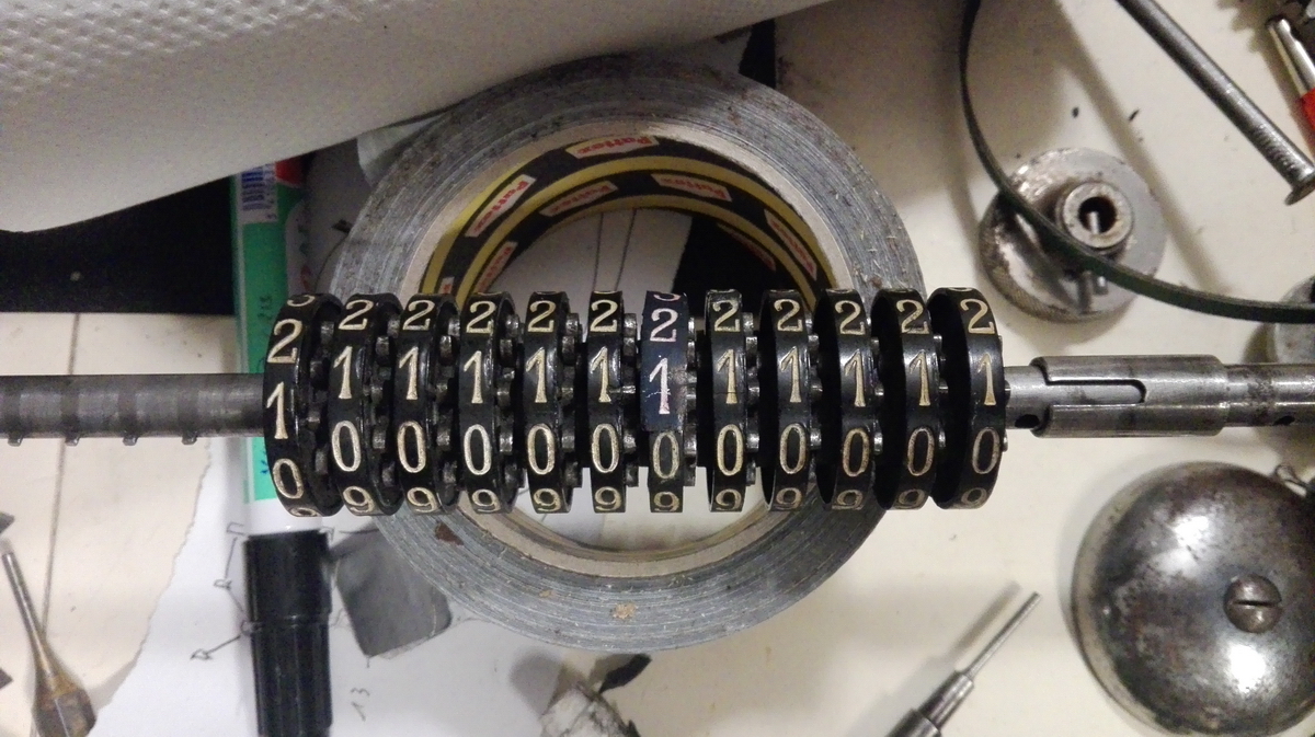
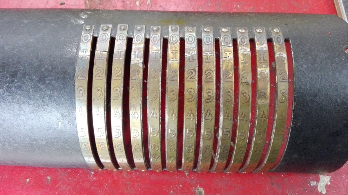
In a Sanders, this happens when the result register numeral wheels are all lined up at "1", and the counter wheels are at white "2". I already knew this, because I made a careful note of it when disassembling my own Sanders... but still I managed to get stuck, and the axle didn't want to come out. The reason for this is that I was unable to get at the notched sleeve mentioned higher, and as long as the two tubular parts at the right side of the axle have the sleeve inside of them, they are centered on the axle, and there is no room for the clearing teeth to come through - they hit the edge of the round distance piece, and the axle will be unable to slide any further. The solution to this conundrum is to carefully maneuver the axle right and left, blocking the position of the notched sleeve with a long thin pick as the axle slides left, and leave it free as it slides right. Eventually it will work its way out like this, to a point where it can be grabbed and pulled out, and now finally the two circular pieces blocking the passage of the clearing teeth on the axle can be pushed forward on the axle, just clearing the way for the clearing teeth to pass through at the front. Phew! I had taken the bar with the springs off the top of the registers for this operation, but in hindsight that wasn't the smartest thing to do, because the wheels aren't fixed this way, and it's much harder to keep the (dis)assembly slots lined up. A well-placed piece of tape helps. So finally, the axle can be slid all the way out, and the damage to the numeral wheels can be assessed.
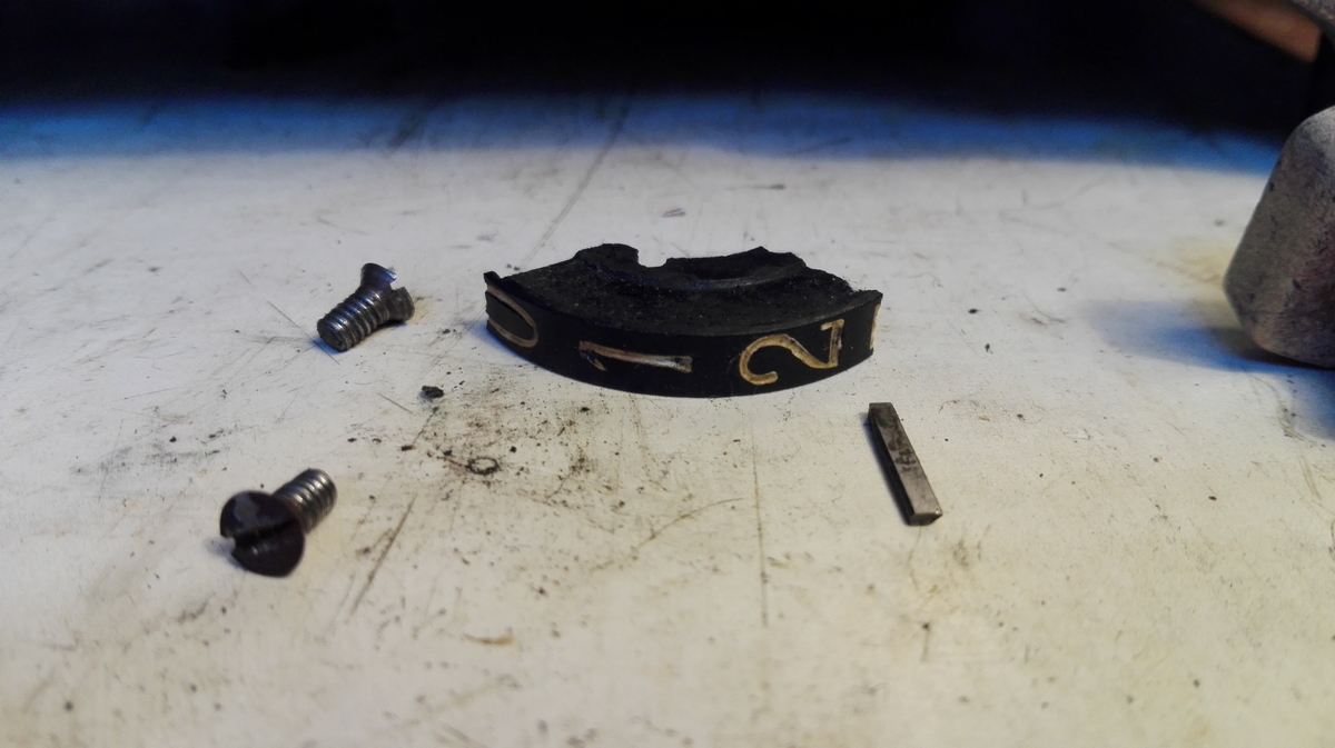
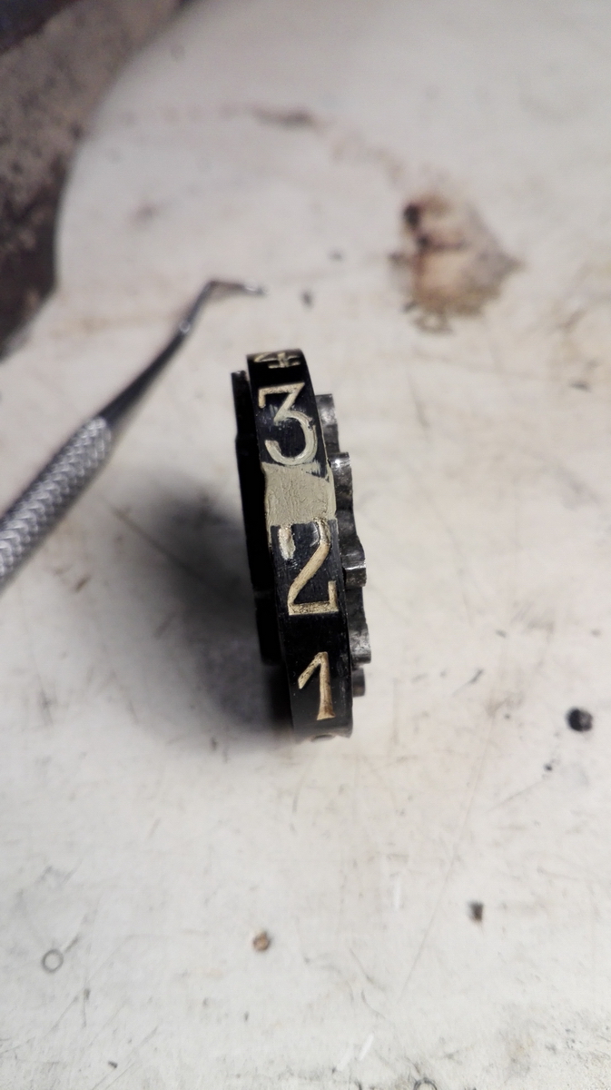
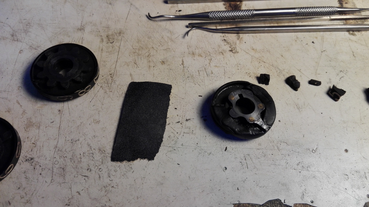
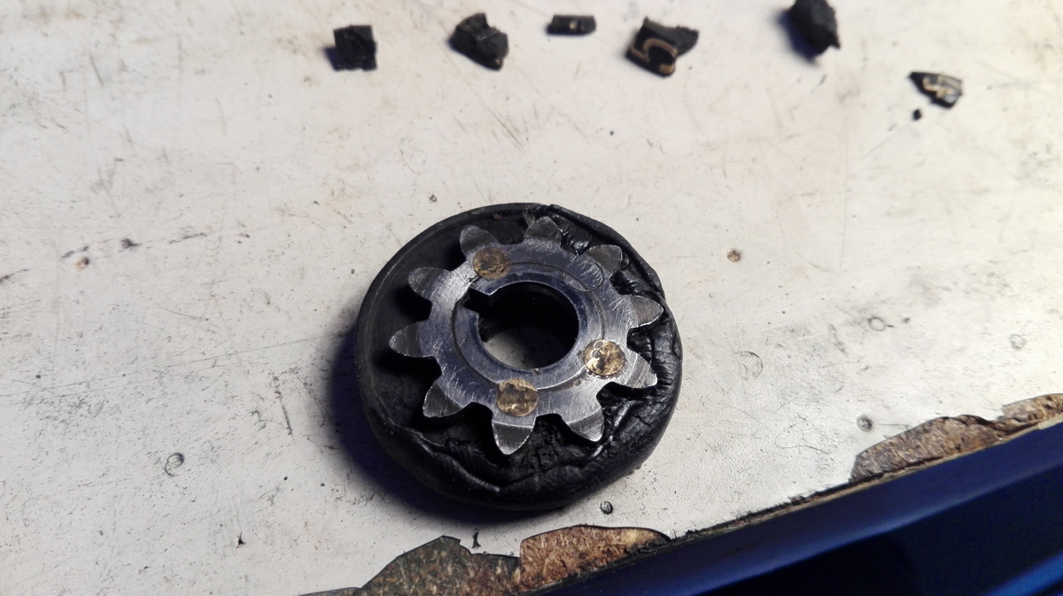
One of them could be glued back together with cyanoacrylate and the small gap that remained could be filled with putty and painted. The other wheel was more of a problem - only the section from the bottom edge of 8 with 9 and 0 was still present, all the rest was pulverized.
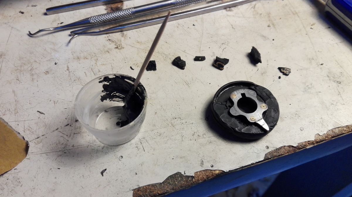
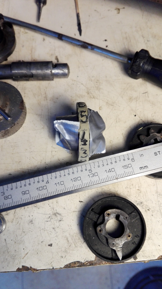
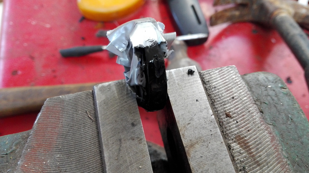
I thought of two possible approaches for a fix - one option was to reconstruct the body of the result wheel out of resin, and engrave the numbers by hand to fill them in with white paint - but that would probably not be so pretty. The other approach would be to scratch the white paste out of a "good" result wheel, and make a cast of it, complete with numbers. Then the numbers would come out great, but the disadvantage would be twofold - I would have to damage a perfectly preserved result wheel, and it would be nearly impossible to mount the freshly cast result wheel onto the steel parts that remained of the original - in the right position and well-centered. So this made me decide to go for option 1, and make the missing part of the result wheel out of Fimmo, a black clay-like polymer that hardens when baked at 110°C, but unfortunately is not that flexible when being moulded, so the baked result wheel would have to be finished afterwards with an exacto knife and filler to make it round, the correct circumference, and with straight sides. Also, the inside of the cavity would have to be cut or ground back, because the Fimmo clay would squeeze into the gaps between the pegs that hold the two halves of the steel gear and carry tooth together, and prevent the clearing from working (or even the repaired wheel from sliding back onto its axle).

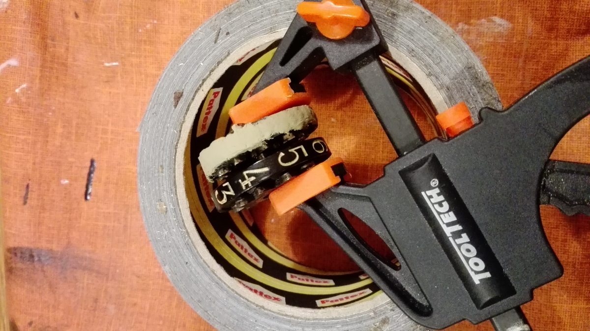
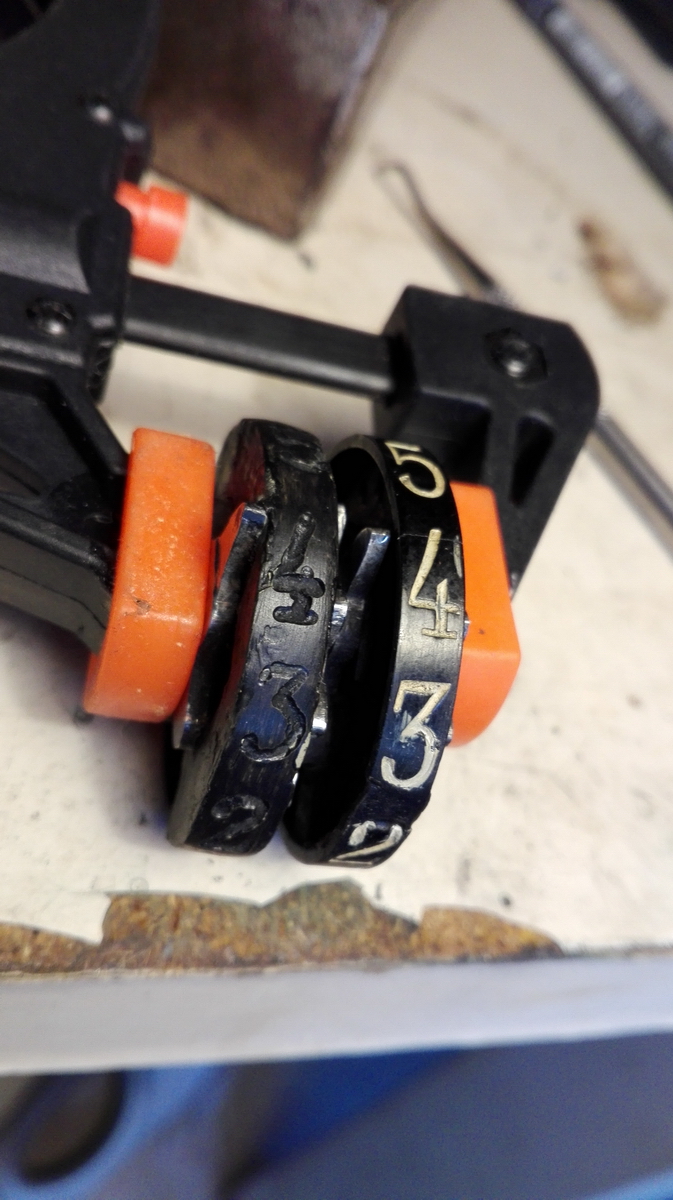
So when all of that was done, I clamped the result wheel next to a good one, and carefully transferred the numbers onto the filler surface with a black sharpie pen.
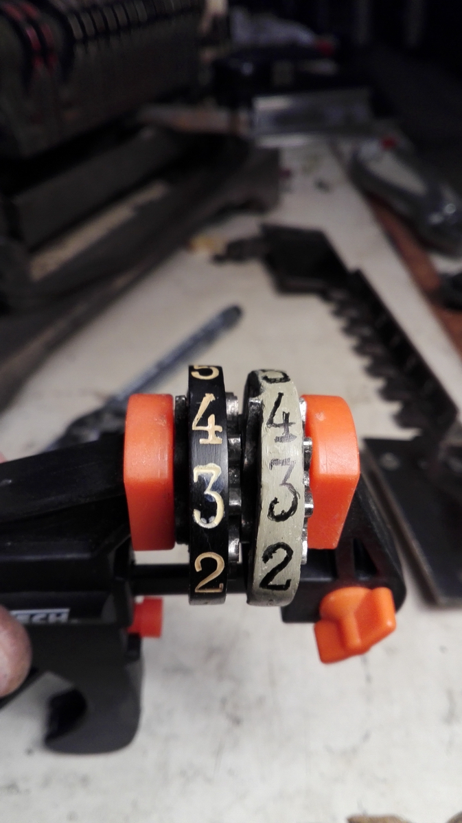
Then, I very carefully engraved the numbers into the surface with a dremel and a 0.2mm milling cutter, being careful to cut away only black. That turned out to be an almost impossible assignment, and the result looked not as well as I would have liked.
The surface was then painted black with matte black paint, and this made me think that I was going to be home free.
Unfortunately, after mixing a batch of acrylic to a colour that matched the off-white of the numbers in the other numeral wheels, it turned out that the matte paint, the car body filler and the Fimmo all became plastic again as soon as the paint was applied, everything became smudged and sticky, the white paint wouldn't harden, and so it only looked good until you tried to polish the excess white from the surface of the wheel, and then everything went pear-shaped.
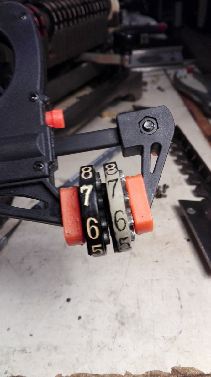
I was not too happy with the result, and after pondering it for a while, I decided there was a third approach - I would photograph all the numbers on a good wheel, and print a strip with the numbers on paper, which could then be stuck to the offending result wheel, and varnished.
That turned out to look a lot better, but you need to be very careful with this result wheel, because the paper is easily ripped or torn, as I quickly found out when I applied tape to the wheels to keep them in position for reassembly, and tore a chunck of the paper right off the result wheel when taking it off. Doh!
So this done, it was on to the reassembly, which, according to all good technical manuals, is "the reverse of disassembly". Unfortunately the reassembly is prone to mistakes.
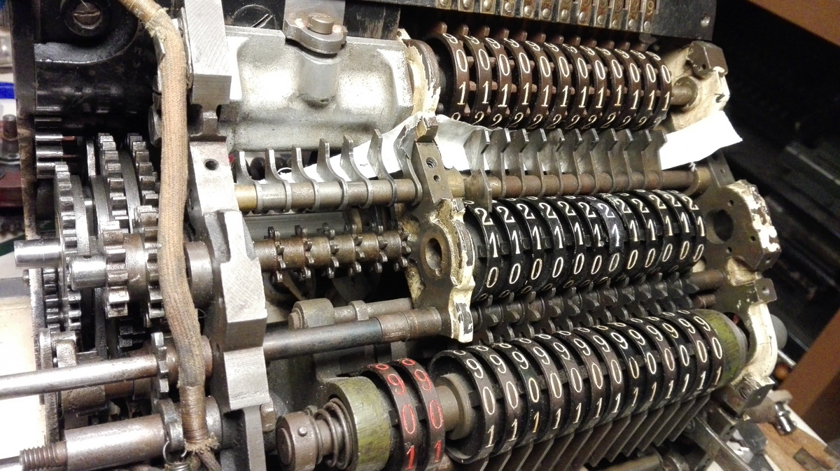
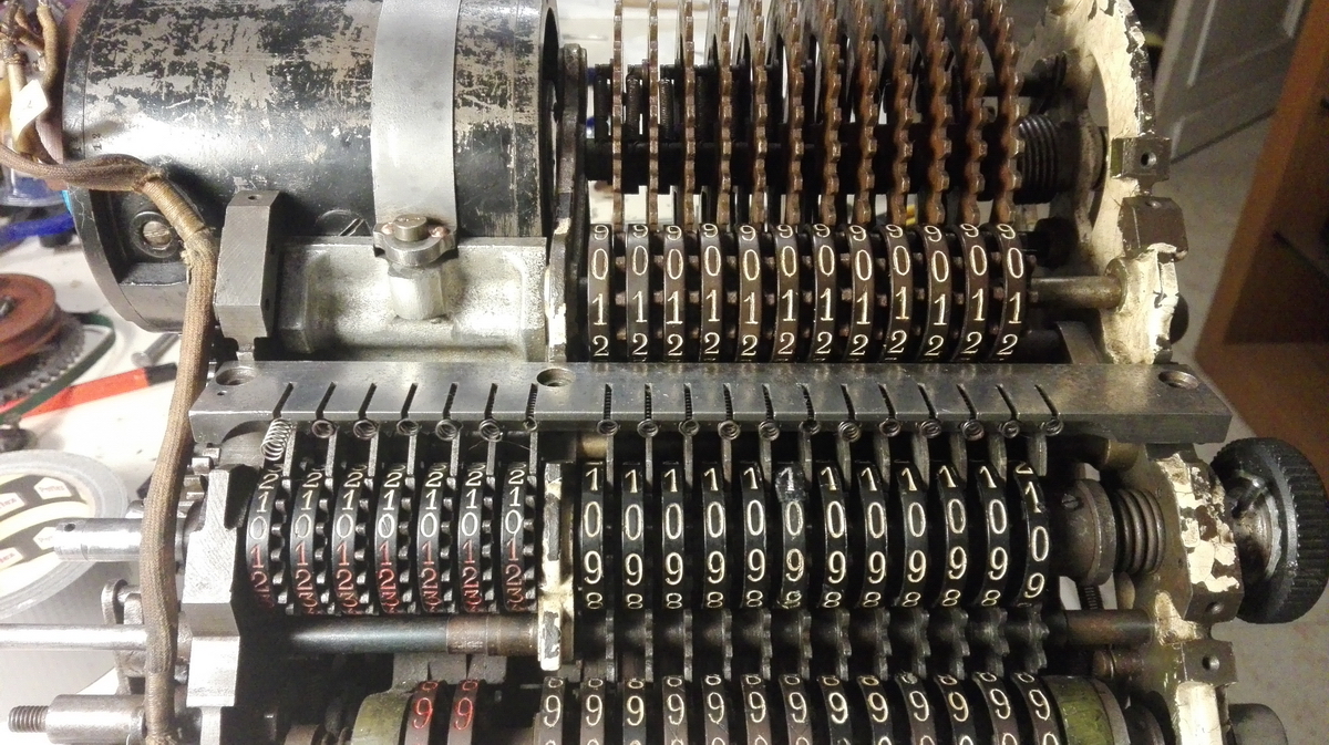
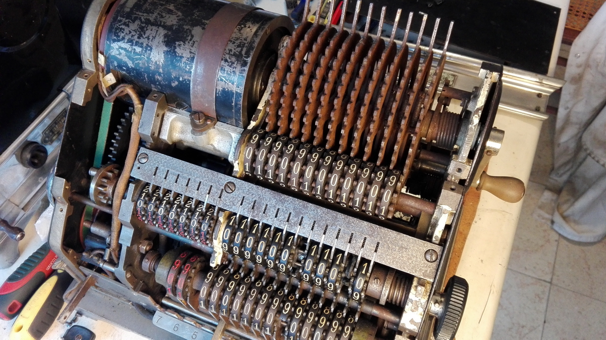
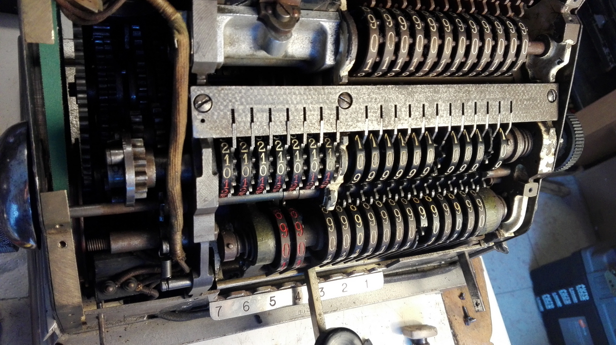
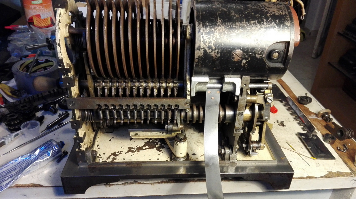
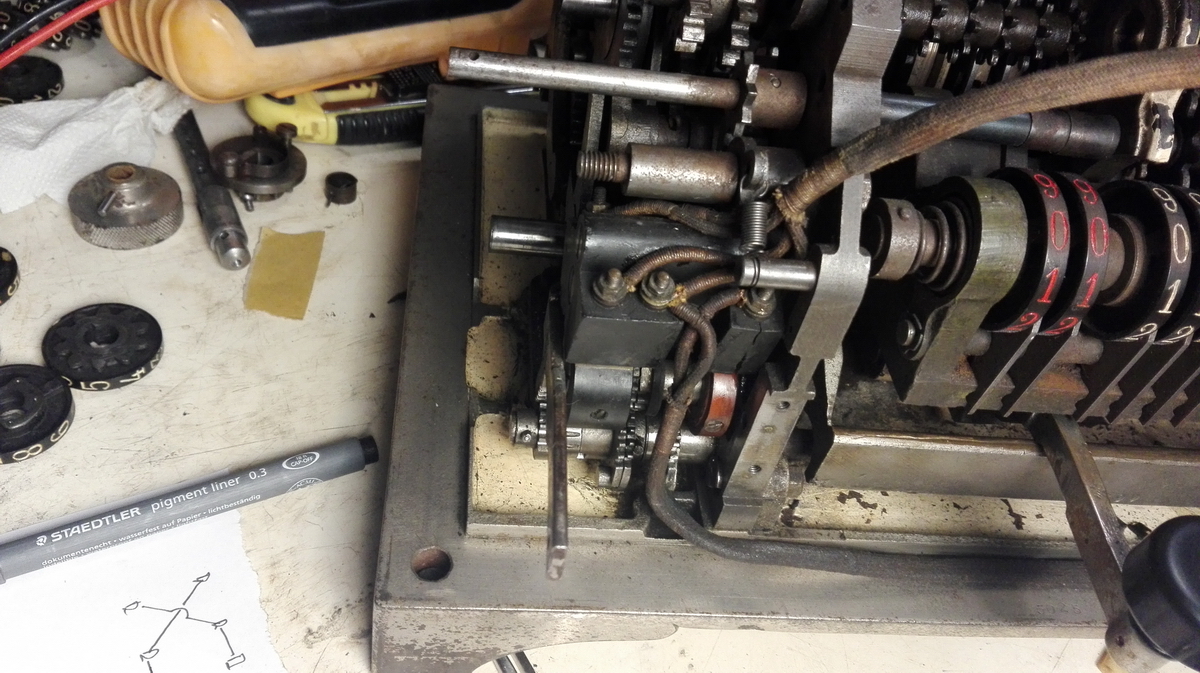
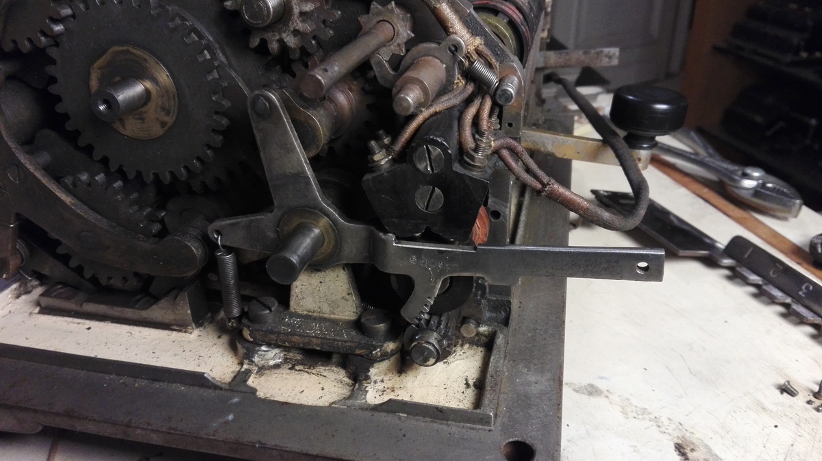
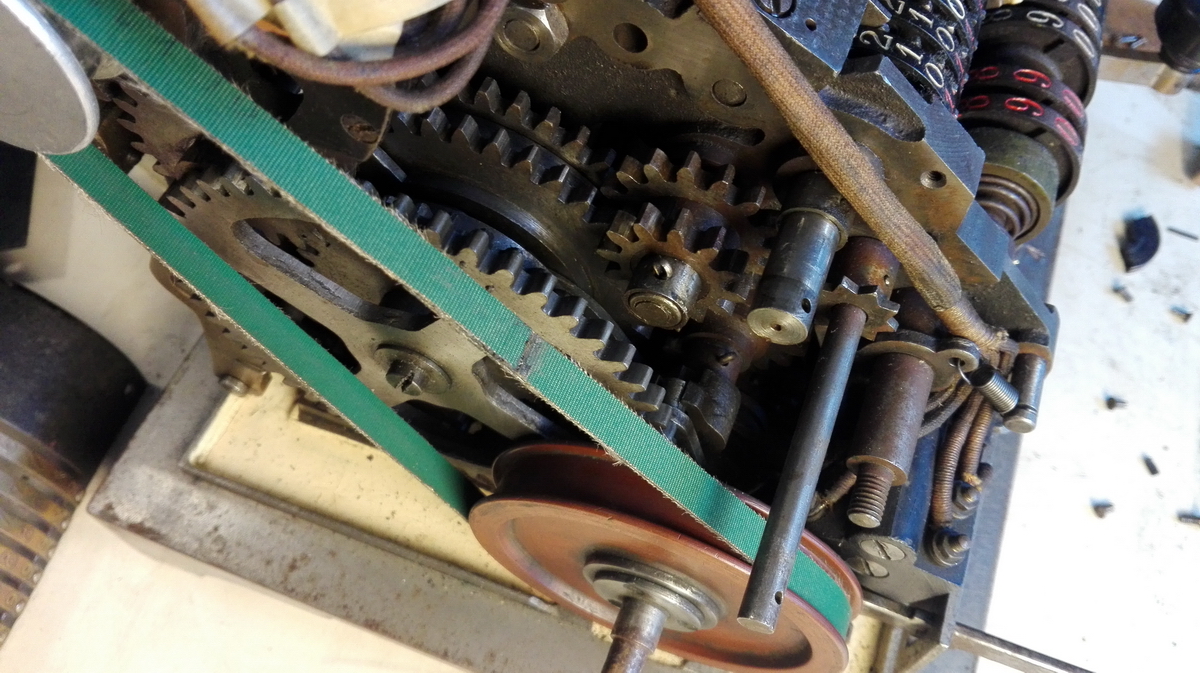
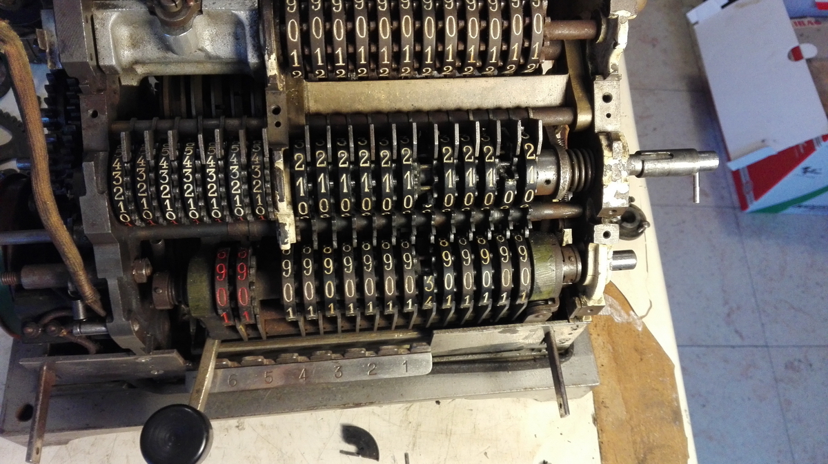
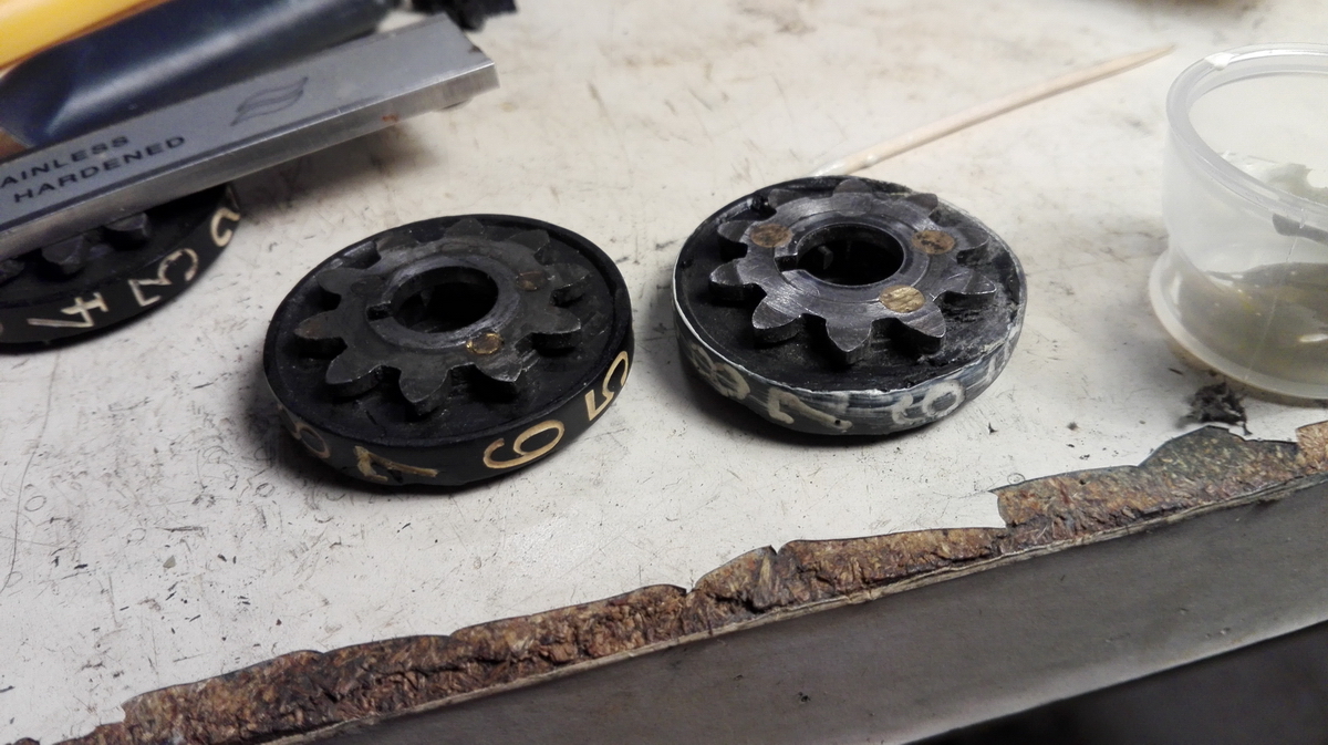
Some that I made: 1. The part with the spring on the right has a fork that fits over another axle further back in the machine, to keep it located. If you forget to put the fork over the axle when reassembling, you're in for another round of disassembly. 2. Four of the result wheels are cast with "44" in the resin part, and the rest appears to have "22". I did notice that the ones with "44" went on the right side of the register, but I did not notice that one of the 22 ones sneakily had the carry tooth rotated over 45 degrees, to make it a tooth for the operation of the bell - and of course this wheel has to go on the left side of the register. You discover this by the tens' carry malfunctioning and the clearing of the register blocking. Uh-oh. See it there on the left, in the picture below ?
3. After putting everything back, including the handwheel and its pin for keeping it in place, discovering that you forgot to put the screws in the handwheel collar - not a problem usually if the handwheel would be a butterfly, but on this machine it's a solid round resin or rubber disk, and you can't reach the screws. So I took it off, put the screws back, then put it back on, tested the register (everything worked) and then discovered that somewhat predictably, I need to take the handwheel back off to put the right side cover of the machine back in place... ugh!
This is the magic angle you need for putting the bar with springs back without all the springs falling into the guts of the machine ...
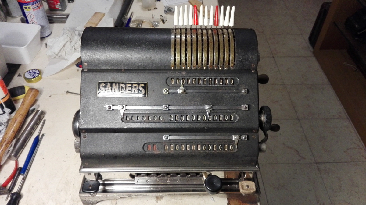
Then we were on the home stretch. I discovered some details about the last person who had occupied himself with a restoration, so I decided to add my details too.
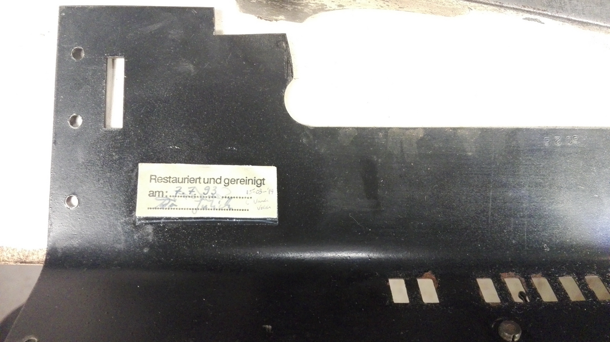
All the metal panels were cleaned, and the brass strips with the numbers on the top cover were glued back into place where they had broken. Soldering would have ruined the paint.
I took off the bars for the decimal sliders to polish them up, and discovered that the metal squares that the rods for the decimal sliders go through are bad quality cast zinc alloy, and very prone to breaking. I glued the two that I broke back together and very carefully polished the rest ...
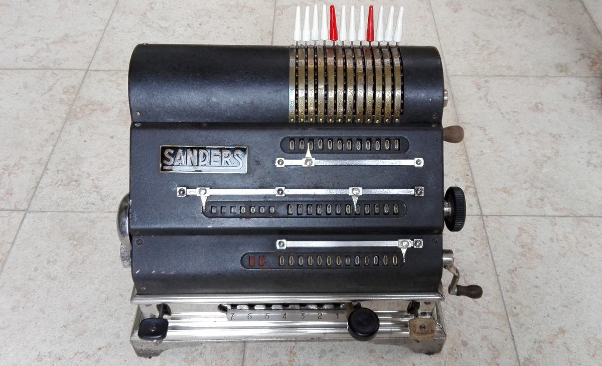
All the panels were put back, as were the clean and partially new setting pin covers. The only thing that I have not reproduced, because I have no idea how it looks, is the spring for the bell, which is missing.
And that concluded the restoration of the machine. If I've done the electrics right, we'll have a video very soon of the machine running under its own power.
And together with the other machine:
This is the video of the machine on test - the only issue it has is that on transferring a number from the result to the memory, the motor stops running a tiny fraction too early, and you need to help the machine along to its rest position manually.